MFJ MFJ-4418 User manual


Contents
INTRODUCTION & FEATURES ............................................................................................................... 3
INTRODUCTION .................................................................................................................................... 3
FEATURES.............................................................................................................................................. 3
Adjustable Output Voltage:.................................................................................................................. 3
Selectable inimum Input Voltage: .................................................................................................... 3
Audio Alert Feature:.............................................................................................................................3
External Boost Enable:......................................................................................................................... 3
Remote Jack: ........................................................................................................................................ 3
TYPICAL SPECIFICATIONS................................................................................................................. 4
EASY START INSTRUCTIONS................................................................................................................. 4
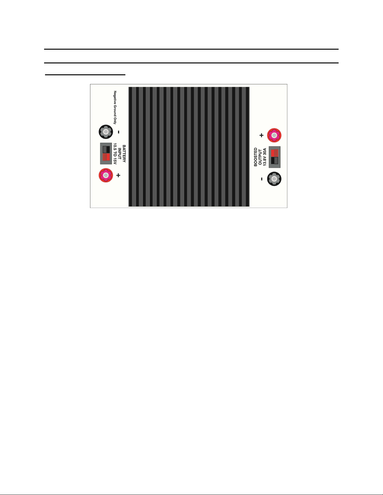
SYSTE CONTROLS AND INDICATORS..............................................................................................5
Top Inputs and Outputs: ...........................................................................................................................5
Controls and Indicators:............................................................................................................................6
CONNECTION AND OPERATION ...........................................................................................................6
ounting .................................................................................................................................................. 6
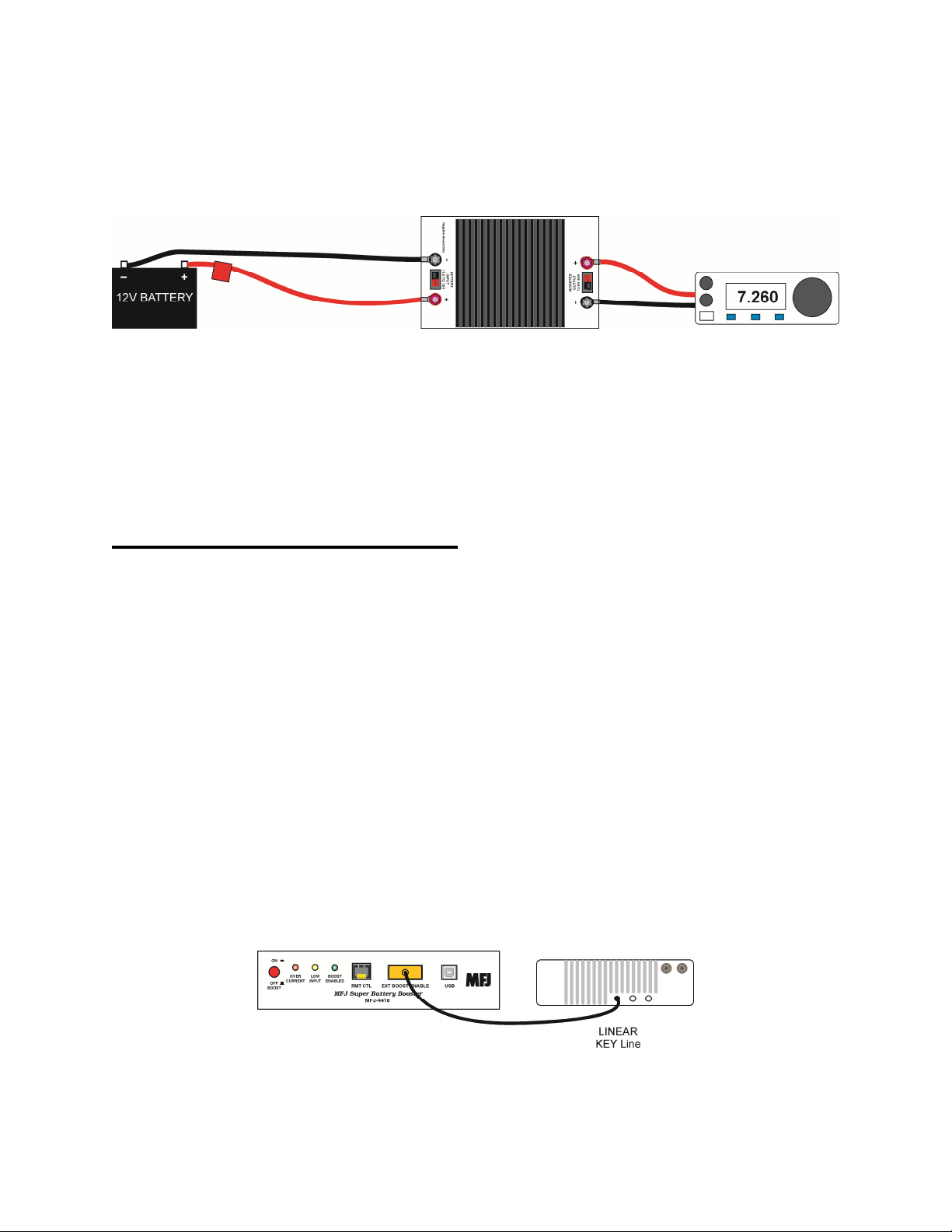
DC Power Connection:............................................................................................................................. 6
Remote and External Control Connections: ............................................................................................. 7
External Control:.................................................................................................................................. 7
Remote Control:................................................................................................................................... 8
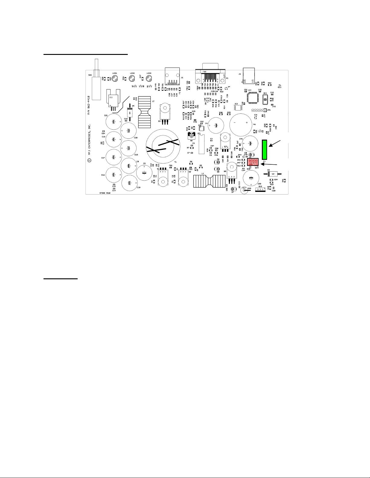
Internal Settings and Fuses....................................................................................................................... 9
JP2: The jumper is accessible by removing the bottom cover. Set the jumper for .............................9
F1 Fuse:................................................................................................................................................ 9
Operation:................................................................................................................................................. 9
Programming the FJ-4418 ....................................................................................................................... 10
THEORY OF OPERATION....................................................................................................................... 13
Input Filtering: ................................................................................................................................... 13
S PS controller:................................................................................................................................14
OSFET drivers and transformer: .................................................................................................... 14
Output Filtering:................................................................................................................................. 14
Over-voltage Protection: .................................................................................................................... 14
IN CASE OF DIFFICULTY....................................................................................................................... 15
Low Voltage Disconnect trips under high demand conditions .......................................................... 15
Enable LED fails to illuminate........................................................................................................... 15
inimum Battery Voltage ................................................................................................................. 16
TECHNICAL ASSISTANCE ................................................................................................................16
Schematics .................................................................................................................................................. 17
FULL 12- ONTH WARRANTY.............................................................................................................. 20
Figures
Figure 1 Top View.......................................................................................................................................................5
Figure 2 Side View .....................................................................................................................................................6
Figure 3 DC Wiring ....................................................................................................................................................7
Figure 4 External Ena le to Amp Key Line ...............................................................................................................7
Figure 5 Ignition Connection and Remote Control Connection .................................................................................8
Figure 6 External Boost Wiring Chart ........................................................................................................................8
Figure 7 Remote Control Wiring Chart ......................................................................................................................8
Figure 8 Board Parts Locations ..................................................................................................................................9
Figure 9 Battery Booster Manager Window .............................................................................................................11
Figure 10 Block Diagram .........................................................................................................................................13
Figure 11 SMPS Section Schematic .........................................................................................................................17
Figure 12 Control Section Schematic .......................................................................................................................18
Figure 13 CPU Section ..............................................................................................................................................19

INTRODUCTION & FEATURES
INTRODUCTION
The MFJ-4418 Super Battery Booster is designed with the serious mobile operator in mind. In
the mobile en ironment low battery oltage can cause output signal distortion, output power
problems and e en transcei er resetting. This low oltage occurs in two ways. First – e en low
resistance wiring can result in noticeable oltage drop. And second when you turn off your
ehicle or remo e a typical battery from the charger, the battery oltage can drop from the
nominal 13.8 olts to 12 olts after a short period of time. With this in mind the MFJ-4418 Super
Battery Booster corrects all of these problems. With its high efficiency boost regulator circuitry,
it will maintain the desired 13.8 olts at up to 25 amps ICAS from oltages as low as 9 olts.
The MFJ-4418 has been redesigned to make the de ice more robust with hea y duty transistors
and rectifiers, impro ed switch mode transformer, and larger heatsinks on ital components. The
EMI filters on the input and output of the MFJ-4418 are designed to reduce noise to a minimum
so radio reception while boosting is normally no problem.
FEATURES
Choice of Input and Output Connections: No need to fumble around looking for connectors. The
MFJ-4418 gi es you a choice of Anderson PowerPoleTM connectors or 5-way binding posts on
the input and output.
Software Managed Adjustments: The user, through MFJ software, can adjust the output
oltage, measure load current, set minimum oltage le els, o er-current trip le els, ignition
control, and other functions.
Adjustab e Output Vo tage: User adjustable output oltage. Factory set at 13.8 olts this
oltage is adjustable anywhere from 12 to 13.8 olts.
Se ectab e Minimum Input Vo tage: You ha e the choice of the minimum input oltage the
MFJ-4418 will operate on. Set from the factory at 11.5 olts you can select 9.5 to 13 olts. This
keeps you from possibly o er discharging your battery and damaging it.
Audio A ert Feature: When enable instantly alerts you when the input oltage drops below the
preset le el.
Externa Boost Enab e: A DE-9 input port with 4 inputs that are used to externally enable the
MFJ-4418. Two inputs when grounded enable the unit and two inputs when taken high (10 to
12V) will enable the unit.
Remote Jack: Allows sampling of the Input Voltage and the Output Voltage. Also allows for
control of the Boost Switch and has an acti e low output for the Low oltage alarm. Direct
connection to the MFJ-4416RC Remote Unit.
RUGGED CONSTRUCTION - Attracti e all-metal cabinet and conser ati e component
selections ensure solid performance for years to come. Fully co ered by MFJ’s “No Matter
What” one year limited warranty.

TYPICAL SPECIFICATIONS
Output Current……………………..……25 Amps ICAS 30A peak.
Output Voltage …………………………13.8 Volts at 9.5-13.8 olts input.
Before attempting to operate your MFJ-4418, please read the manual thoroughly. It contains
important details about setting up your unit to obtain the best performance.
EASY START INSTRUCTIONS
1. Prepare input and the output cables for the MFJ-4418. It is recommended to use #12 or
larger wire for both the input and output cables. MFJ has cables a ailable for the output
side for use with most HF and VHF/UHF radios.
2. Prior to connecting the radio and battery, plug the input and the output cables in to the
MFJ-4418 and ensure the polarity is correct.
3. Plug the output of the MFJ-4418 into your radio and then attach the input to your battery.
4. You are now ready to operate. If not using external switching, depress the enable switch.
NOTE: The MFJ-4418 is not designed to boost the vo tage of a 6V
e ectrica system up to 13V and wi not run on a positive ground
system. It wi a so not reduce the vo tage of a 24 vo t system to 13V.

SYSTEM CONTROLS AND INDICATORS
Top Inputs and Outputs:
Figure 1 Top View
1. 5-Way High Power Binding Post Negati e Input.
2. Anderson PowerPoleTM Input.
3. 5-Way High Power Binding Post Positi e Input.
4. 5-Way High Power Binding Post Positi e Output.
5. Anderson PowerPoleTM Output.
6. 5-Way High Power Binding Post Negati e Output.
1
2
3
4
5
6

Contro s and Indicators:
1 2 3 4 5 6 7
Figure 2 Side View
1. Boost On/Remote: This switch enables the Battery Boost function when in and when
out enables the Remote Boost Enable feature.
2. Over Current LED: Lights when o er current sense is tripped.
3. Low Input LED: Lights when input is below the preset minimum input oltage.
4. Boost Enab e LED: This LED is illuminated when the Switching Regulator is enabled.
5. Remote Contro : This Jack allows the MFJ-4416BRC Remote Control and metering
unit to be attached to the MFJ-4418. This allows remote monitoring of the Input Voltage
and Output Voltage. It also allows Remote Enabling and Audible alarm of the MFJ-
4418. Perfect for remote placement of the MFJ-4418.
6. Externa Boost Enab e: This connector allows remote enabling of the booster from an
ignition switched line, the radio amp key line, or other remote de ices
7. USB: The port to connect a computer for setting up the MFJ-4418 and monitoring the
MFJ-4418 functions.
Not shown on the back side there is a ground lug a ailable for chassis grounding.
CONNECTION AND OPERATION
Mounting
Place the MFJ-4418 in a dry, out of the way place, where air can circulate o er the heatsink. Do
not mount it in a location where it can get wet. Place it in a location where the case can be
grounded with short ground leads.
DC Power Connection:
The MFJ-4418 is designed to boost oltages as low as 9.5V up to 13.8V at up to 30A peak. At
high currents the oltage drop from e en large gauge wires can be appreciable for e en short
runs. It is recommended to use a large gauge wire (such as #8 or #10) to reduce the oltage drop.
Connect the wire to the battery or other high current terminal on the ehicle for best results.
Connection to the lighter jack or a smaller fuse block is not recommended because of the smaller
gauge wires used in the automoti e wiring harnesses. A fuse in the positi e line near the battery

is recommended to protect the wiring from accidental shorts circuits. Connect the radio to the
MFJ-4418 using the wiring harness from the radio manufacturer. MFJ carries a number of cables
that can be used for this purpose. See page 16 for model numbers.
Figure 3 DC Wiring
Terminal connections to and from the MFJ-4418 can use the 30A Anderson PowerPole
terminals, crimp lugs, banana plugs or wires straight to the 5 way binding posts. Follow the
connector manufacturers’ instructions for attaching the terminal lugs. Make sure the lugs are
tightly crimped to insure they do not pull loose. If the binding posts are used place ring lugs or
spade lugs on the wire and make sure the binding posts are tightened down so the lug will not
pull off the post. Wires that connect to the binding posts directly are not recommended because
they can pull loose easily.
Remote and Externa Contro Connections:
Externa Contro : The MFJ-4418 can be enabled externally through the “EXTERNAL BOOST
ENABLE” connector allowing the unit to be enabled a number of ways including the ignition
line and the radio amplifier key line. There are a total of 4 control lines. Two will enable the
MFJ-4418 when grounded and two will enable the MFJ-4418 when tied to a 4 to 13V source.
Connecting either pin 1 or 2 to the amplifier key line of the radio if it has one will set up the
MFJ-4418 to enable only when transmitting. This will help reduce any noise that may be
generated by the switching boost circuit while recei ing. See your radio manual for the proper
connections to the radio.
Connecting either pin 3 or pin 4 of the external control connector to an accessory line will allow
the booster to be enabled when the ehicle is turned on or when it is set in accessory on the
ignition switch. This will help reduce the current drain on the battery when the ehicle is off.
Not all radios are set up to be able to key the MFJ-4418. In those cases the boost button will ha e
to be set to ON or programmed for “Enable on input at low limit”. There is no RF sense built
into the MFJ-4418.
Figure 4 Externa Enab e to Amp Key Line

Remote Contro : The optional Remote Control MFJ-4416BRC can be used to monitor and
control the MFJ-4418 allowing the MFJ-4418 to be mounted in an out of the way place in the
ehicle. The connection is a normal CAT-5 cable that plugs into the MFJ-4416BRC and the
MFJ-4418 REMOTE CONTROL RJ-45 Jack.
Programmab e Interna Contro : The programmable “Enable on input at low limit” function
will set up the MFJ-4418 to boost only when needed with the programmable settings. With the
“Enable on input at low limit” check box checked the MFJ-4418 will boost whene er the oltage
has dropped below the “ENABLE LOW LIMIT” setting and will quit boosting when the “Enable
High Limit” is obtained. This setting is handy to reduce any noise from the switching circuit
when the MFJ-4418 is not needed to boost the oltage. See “Programming the MFJ-4418”
section. This mode does not require any connections to the radio and does not require the Boost
Enable switch to be pushed in. Any external connections or the Boost Enable switch will
o erride this function.
Figure 5 Ignition Connection and Remote Control Connection
EXTERNAL BOOST CONNECTOR
DE-9 Pin Function
1 GROUND TO ENABLE pulled to +5V wit internal 1.6K pull-up resistor.
2 GROUND TO ENABLE pulled to +5V wit internal 1.6K pull-up resistor.
3 HIGH TO ENABLE any voltage between 4 and 15V
4 HIGH TO ENABLE any voltage between 4 and 15V
5 13V DC OUTPUT resettable fuse limited to 100mA (boosted)
6 to 9 GROUND
Figure 6 External Boost Wiring Chart
REMOTE CONTROL CONNECTOR
RJ-45 Pin Function
1 INPUT VOLTAGE, resettable fuse limited to 100mA (unboosted)
3 ENABLE SIGNAL, ground to enable.
5 LOW VOLTAGE ALARM SIGNAL, ground indicates alarm condition.
7 OUTPUT VOLTAGE, resettable fuse limited to 100mA (boosted)
2, 4, 6, 8 GROUND
Figure 7 Remote Control Wiring Chart

Interna Settings and Fuses
Figure 8 Board Parts Locations
JP2: The jumper is accessible by remo ing the bottom co er. Set the jumper for
UNSWITCHED (jumper 1 to 2, default) or IGNITION SENSE (jumper 2 to 3). “Unswitched”
powers the microcontroller from the battery input and the “Ignition Sense” from the ignition
sense line.
F1 Fuse: The fuse is accessible by remo ing the bottom co er. This fuse is a 30A automoti e
blade type. Do not use a fuse of a higher current rating.
Operation:
Once wired in the MFJ-4418 will boost the incoming oltage to 13.8V when enabled for any
oltage between the minimum oltage and 13.8V. If the incoming oltage is abo e what the
output oltage is set to the output oltage will rise to the incoming oltage minus about a half
olt. When the MFJ-4418 is not energized the input oltage is passed to the output connectors
and has about a half olt drop due to the internal rectifiers.
There are protecti e diodes that protect the input and output from exceeding 18V or being
re erse wired.
The MFJ-4418 is not designed to boost the oltage of a 6V electrical system up to 13V and will
not run on a positi e ground system. It will also not reduce the oltage of a 24V or higher system
to 13V.
Fuse F1
Jumper JP2

Programming the MFJ-4418
The Power Booster Manager is a PC program capable of running on Windows XP, 7 and later
operating systems. It is not designed to run on Apple computers. The software and dri ers are
a ailable on the MFJ Enterprises web site.
1. Program Installation
a. Windows 7 and XP
i. DO NOT plug into the USB port on the MFJ-4418 until you install the
dri er as Windows will install a generic serial USB dri er which is not
compatible. To install the dri ers unzip and run the MFJ-4418 Dri er
Installer.exe. The program will place the dri ers in the correct directory
for use.
ii. If you accidentally install the wrong dri er go to the Control Panel’s
“De ice Manager” window and find the de ice under “Ports (Com and
LPT)” or “Other De ices”. On the Dri er tab select update dri er. Then
select the proper dri er which came with the manager program and update
it.
b. Windows 10
i. The default USB dri er used by Windows 10 will work with the MFJ-
4418. There is no need to run the MFJ-4418 Dri er Installer program.
ii. You can do a dri er update by going to the Control Panel’s “De ice
Manager” window and find the de ice under “Ports (Com and LPT)” and
on the Dri er tab select update dri er and search on the internet. The more
recent Microchip dri er will be installed.
c. Unzip and run the MFJ-4418 Battery Booster Manager Installer.exe program to
install the MFJ-4418 Battery Booster Manager Program. The installer will place
an icon on the desktop to run the program.
d. Apply power to the MFJ-4418 and plug in the USB cable between the unit and the
computer. The computer should find and use the dri ers to communicate with the
MFJ-4418. Use the “Ports (Com and LPT)” selection in the De ice Manager on
the Control Panel and make note of the COM port number. If the COM Port is 10
or higher then change the number to something 9 or lower in the Ports Settings
tab Ad anced section. The Battery Booster Program will not handle COM Ports
o er COM9.

2. The Manager window is described below:
Figure 9 Batter Booster Manager Window
a. Comm Port: This pull down box allows you to set the COM port used with the
USB connection.
b. Connect Button: This button connects and disconnects from the MFJ-4418. The
button label changes following the role the button plays.
c. Write Data Button: This button writes any changes made to the EEPROM on the
4418 making them permanent. If you forget to write the data the MFJ-4418 will
automatically sa e it when the USB connection is closed. It is a good idea to write
the data when the changes are made because of the power is interrupted prior to
closing the USB port the changes will be lost.
d. Input Vo tage, Output Vo tage and Output Current: These displays are
updated e ery ½ second and display in olts and amps.
e. IN LOW indicator: If the input oltage falls below the alue set in the “Input
Low Limit” setting the supply will stop pro iding boost oltage and this indicator
will turn red.
f. HI CURRENT Indicator: If the output current exceed the “Current Limit”
setting or exceeds 35 amps the boost supply will turn off all output oltage. The
high current indicator will turn red and the supply will be locked out until the
boost enable signals are all in the non-boost state or the power is cycled.
g. ENABLED Indicator: When the boost supply is enabled by any of the enable
signals this indicator will turn green.

h. CURRENT LIMIT: This pull down box allows the current limit to be set from 5
to 30 Amps in 1 amp steps. This control works with the Electronic Fuse setting
and Slow blow time to select the current protection pro ided.
i. INPUT LOW LIMIT: This pull down box allows setting the absolute low le el
of the input oltage from 9.5 to 13.0 olts in ½ olt steps. This limit is a hard stop
limit and the supply will turn off all output when the input is below this alue for
more than 1/3 of a second.
j. ENABLE LOW LIMIT: This pull down box work in conjunction with the
“Enable on input at low limit” Check Box. This setting allows the input oltage
le el to turn on the boost supply automatically when the input oltage falls below
this alue. This setting can be from 10.5 to 13.0 olts in ½ olt steps. This is a
latching enable signal that will be cleared when the input oltage exceeds the
alue set in the “Enable High Limit” setting. This hysteresis minimizes cycling
caused when the battery or other source is partially discharged and has higher
output impedance. Make sure the Enable High Limit is greater than the Enable
Low Limit.
k. ENABLE HIGH LIMIT: The limit where the MFJ-4418 will shut off the boost
supply when the input is abo e this setting. Used in conjunction with the “Enab e
on input at ow imit” Check Box. Make sure the “Enable High Limit” is greater
than the “Enable Low Limit”.
l. E ectronic Fuse: This selects either fast or slow blow operation. In fast blow the
delay time is 1/10 second and in slow blow the delay time is adjustable by the
“Slow Blow Time” pull down box.
m. Enab e on input at ow imit: This setting allows the input oltage le el to turn
on the boost supply automatically when the input oltage falls below the” Enable
Low Limit” alue and off when the oltage exceeds the “Enable High Limit”.
n. Power Contro ed By Ignition Lead: This checkbox enables the Ignition lead
sense functions.
o. Ignition Ho d Time: This setting works with the “Ignition Turn Off Timer” and
“Power controlled by ignition lead” checkboxes. When the power is controlled by
the ignition lead and the “Ignition Turn Off Timer” checkbox is checked this
setting controls the hold on time after the ignition is turned off. This allows you to
complete a QSO without the fear of lea ing the radio on as the MFJ-4418 will
turn off the output oltage at the end of this time unless the ignition is again
turned on.
p. Soft Start Enab ed: Allow the power supply to pulse width control the charge
into the output capacitors minimizing the surge currents.
q. Audib e A arm On Low Vo tage Enab ed: Enables internal audible alarm on
low input oltage. The alarm always sounds on high current. When this is enabled
and power is remo ed from the MFJ-4418 the alarm may sound till the capacitors
discharge.
r. Set Output Vo tage: Allows the output oltage to be adjusted up and down.

s. Peak Current Disp ay: This alue is the peak current seen during the supply
operation. This alue is olatile and will be zeroed when the power supply input
oltage is remo ed or the “Reset” button in pressed.
t. Average Current Disp ay: This alue is the a erage current deli ery by the
supply. This alue is olatile and will be zeroed when the power supply input
oltage is remo ed or the “Reset” button in pressed.
u. Reset Button: This button clears the “Peak Current Display” and “A erage
Current Display”. It does not reset any other functions.
THEORY OF OPERATION
Figure 10 B ock Diagram
Input Fi tering: The input filter consists of C13 which pro ides EMI filtering followed by L1,
C12 and C11 which are a low pass filter at the alternator which range. C8, C9 and C10 pro ide
low ESR energy storage which helps to suppress input noise while pro iding energy during input
low oltage transient periods. Diode D1 and capacitors C3 and C4 pro ide additional filtering
and energy storage feeding the SMPS controller IC1. The additional energy storage is isolated
from any transient load causing a oltage drop on the input protecting IC1 from resets and gaps

in the boost function. Diode D2 is a transient suppressor diode and acts to protect the unit against
transient oltages greater than 15 Volts.
SMPS contro er: IC1 is a packaged SMPS controller with built in oltage reference. This is a
constant frequency pulse width modulated regulator with built in dri er for the MOSFET gates.
The switching frequency is set to 50Khz. The controller is enabled or disabled by the soft start
control input. This input is grounded to disable the SMPS boost supply. An open collector of Q8
and series resistor R44 pro ide the control function. Feedback from the output oltage is
pro ided by the oltage di ider consisting of R9, electronic pot IC5, and R10. This feedback is
compared against the oltage reference to adjust the pulse width and resulting oltage output.
The oltage reference is supplied to the analog control section for oltage le el decision making.
MOSFET drivers and transformer: A push pull configuration using two FDP56N06
MOSFETs dri es the transformer T1. T1 uses two tapped windings allowing the input oltage to
be placed in series with the SMPS output oltage. The turns ratio is 1.57:1 in series with the DC
input oltage results in a boost of 1.57 o er the input oltage. The tapped points on the two
windings are fed to the common cathode rectifier pair D3. Using MOSFET Q1 as an example for
both the Q1 and Q2 circuitry. The gate circuit consists of R6, R3 and FB1. R6 and FB1 minimize
ringing and parasitic oscillations while R3 is a base drain that discharges the gate to substrate
capacity while the unit is not powered. The storage of energy in the gate capacity as a result of
residual energy from pre ious operation or static can allow both transistors to attempt to conduct
during the next power up cycle before the control IC takes control of the gate usually destroying
one or both MOSFETs.
Output Fi tering: The output filter consists of toroid inductor L2 with capacitors C14 through
C22 that act as a low pass filter and energy storage bank. The total energy storage is 23,500 UF
distributed o er 5 capacitors to minimize ESR. Capacitor C22 is located close to the output and
ser es as an EMI suppressor. Diode D4 is a 15 olt transient suppressor diode and protects the
unit from transient seen on the output terminals.
Over-vo tage Protection: The microprocessor monitors the output oltage and when the oltage
exceeds the programmed set oltage the input PMOS transistor Q9 is turned off turning off
power to the remainder of the MFJ-4418.
Microprocessor Contro : The CPU is the brains of the MFJ-4418 and controls most aspects of
the operation.
The MFJ-4418 has direct control o er the power feed and unlike the MFJ-4416 booster it can
turn off the output oltage under CPU control. This allows the MFJ-4418 to pro ide both
operational shutoff of the attached radio and shutoff in a failure mode to protect both the MFJ-
4418 and the radio. The operational power control mode is based on the use of the ignition lead
and power will be switched on and off by this lead. In addition a hold on timer can allow the
MFJ-4418 to pro ide power for a programmable period of time post the ignition turn off. This
allows the attached radio to operate with the ignition off without the concern of forgetting to turn
it off resulting in a dead battery. The failure modes detected and used for power shutoff are low
input oltage below the programmable point, high output current abo e the programmable limit
and high output oltage abo e 15Volts.
The MFJ-4418 pro ides soft start and this is acti ated on power up or when the ignition lead
senses +12V. The software waits 500 milliseconds for the supply to stabilize and then switches

on MOSFET Q12 which pro ides current limited charging of the filter capacitors. This limits the
inrush currents to 50Amps. After 200 milliseconds the main power MOSFET is acti ated. This
operation is uni ersal to all power on modes. If the “Soft Start” checkbox is used the abo e
process is started followed by pulse width modulation of the power switch minimizing the
a erage charging current so the supply can start into a load without a significant current transient
sent back to the source.
The CPU monitors and integrates the input oltage and uses the resulting le el for two functions.
The boost enable is allowed if the input oltage is abo e the programmable “Input Low Limit”.
The input oltage maybe utilized to turn on the oltage boost by enabling this function. When
the input oltage falls below the programmable “Enable Low Limit” the boost will be enabled
and when the input oltage exceeds the “Enable High Limit” the boost will be disabled. Ha ing a
guard band between the two oltages minimizes the possibility of cycling on and off when the
battery gets low and its terminal impedance increases.
The CPU monitors the output oltage and erifies it is with the tolerance of the programmed
output oltage. This is also the high output oltage check and if 15 Volts is exceeded the CPU
will shut down the power and boost function protecting the attached radio and the MFJ-4418
from internal or external oltage faults. If this fault occurs the supply is locked out till the power
is remo ed. The high current led will blink indicating a high oltage fault occurred.
The CPU monitors for o ercurrent and will shut down the power and boost function should the
output current exceed the programmable alue. The high current LED will be illuminated and the
supply locked out until the enable signal is remo ed.
The boost enable can be initiated by low input oltage, positi e keying inputs, negati e keying
inputs, boost switch mounted on the MFJ-4418, boost switch mounted on the remote or by
grounding pin 7 of X1. The CPU will check to see if the input oltage is OK and there is no
failure lock out before enabling the boost and will check for input oltage or failure during boost
operating disabling it if required.
The CPU pro ides a USB dri er to communicate with the Power Booster Manager software
package and recei es data through this connection to the manager.
IN CASE OF DIFFICULTY
Low Vo tage Disconnect trips under high demand conditions
This can be caused by 2 things. First ensure your battery is charged. A discharged battery will
reco er oltage under low current conditions, but once current is drawn it will immediately drop
below the cutout oltage. Second, ensure the wiring on the input side of the unit is adequate for
the current being drawn and the lengths of the cable run.
Enab e LED fai s to i uminate.
Ensure that you are either feeding one of the enable lines from the radio amplifier key line into
the unit or the Enable/Disable switch is depressed.
When programmed for “Enable on Low input” where the le el is abo e the low limit and has
been abo e the Enable on High limit to turn off the boost function. This would be normal. If it

does not try to boost when below the Enable Low Limit and abo e the Input Low Limit check
the programming to insure the programming is correct.
Minimum Battery Vo tage
According to battery manufacturers ehicle batteries are normally considered drained at 11.6V
with no load. Under load the oltage will be a little lower. Below about 9-10V the oltage will
drop fast with any load. The battery life may suffer and the ehicle may not start when the
battery is that low.
http://www.eetimes.com/author.asp?section_id=36&doc_id=1320644
Noise Reduction
Although e ery effort was made to reduce switching noise RF noise is a possibility. To reduce
noise to a minimum ground the case of the MFJ-4418 to the automoti e chassis with as short of a
wire or grounding braid as possible. Clamp on ferrite beads can be used on the input and out
power leads to further reduce noise. 1 or 2 turns through the bead will help.
TECHNICAL ASSISTANCE
If you ha e any problem with this unit first check the appropriate section of this manual. If the
manual does not reference your problem or is your problem is not sol ed by reading the manual,
you may call MFJ Technical Ser ice at 662-323-0549 or the MFJ Factory at 662-323-5869. You
will be best helped if you ha e your unit, manual and all information on your station handy so
you can answer any questions the technician may ask.
You can also send questions by mail to:
MFJ Enterprises, Inc.
300 Industrial Park Road
Stark ille, MS 39759
by Facsimile (FAX) to 662-323-6551
or by email to [email protected].
Send a complete description of your problem, an explanation of exactly how you are using your
unit, and a complete description of your station.
Avai ab e Accessories:
MFJ-4416BRC Remote Control
MFJ-5262 CAT5E cable
Radio Power Cab es:
MFJ-5112, MFJ-5112M Yaesu, Kenwood, Icom VHF/UHF
MFJ-5535, MFJ-5535M Yaesu, Kenwood, Icom HF
MFJ-5538, MFJ-5538M Yaesu 4 pin HF

Schematics
Figure 11 SMPS Section Schematic

Figure 12 Contro Section Schematic

Figure 13 CPU Section

FULL 12-MONTH WARRANTY
MFJ Enterprises, Inc. warrants to the original owner of this product, if manufactured by MFJ Enterprises,
Inc. and purchased from an authorized dealer or directly from MFJ Enterprises, Inc. to be free from
defects in material and workmanship for a period of 1 months from date of purchase provided the
following terms of this warranty are satisfied.
1. The purchaser must retain the dated proof-of-purchase ( ill of sale, canceled check, credit card or
money order receipt, etc.) descri ing the product to esta lish the validity of the warranty claim and su mit
the original or machine reproduction of such proof of purchase to MFJ Enterprises, Inc. at the time of
warranty service. MFJ Enterprises, Inc. shall have the discretion to deny warranty without dated proof-of-
purchase. Any evidence of alteration, erasure, of forgery shall e cause to void any and all warranty terms
immediately.
2. MFJ Enterprises, Inc. agrees to repair or replace at MFJ's option without charge to the original
owner any defective product provided the product is returned postage prepaid to MFJ Enterprises, Inc. with
a personal check, cashiers check, or money order. This is good on all products except antennas and software
to cover postage and handling for return from in warranty service. We also take MasterCard, Visa,
American Express, and Discover credit cards. Postage and handling may vary according to the weight of the
product in question. You should specify what type of delivery service you wish. We can send y UPS, U.S.
Postal service or Fedex. MFJ doesn’t guarantee delivery y US Postal Service.
3. MFJ Enterprises, Inc. will supply replacement parts free of charge for any MFJ product under
warranty upon request, provided the following terms are satisfied. MFJ must receive the original parts you
wish to replace, your proof-of-purchase, and a personal check, cashiers check or money order must e
provided to cover postage and handling. Postage and handling may vary according to the weight of the
product in question. We also take MasterCard, Visa, American Express and Discover credit cards.
4. This warranty is NOT void for owners who attempt to repair defective units. Technical
consultation is availa le y calling (662) 323-5869.
5. This warranty does not apply to kits sold y or manufactured y MFJ Enterprises, Inc.
6. Wired and tested PC oard products are covered y this warranty provided onl the wired and
tested PC board product is returned. Wired and tested PC oards installed in the owner's ca inet or
connected to switches, jacks, or ca les, etc. sent to MFJ Enterprises, Inc. will e returned at the owner's
expense un-repaired.
7. Under no circumstances is MFJ Enterprises, Inc. lia le for consequential damages to person or
property y the use of any MFJ products.
8. Out-of-Warrant Service: MFJ Enterprises, Inc. will repair any out-of-warranty product
provided the unit is shipped prepaid. All repaired units will e shipped COD to the owner. Repair charges
will e added to the COD fee unless other arrangements are made.
9. This warranty is given in lieu of any other warranty expressed or implied.
10. MFJ Enterprises, Inc. reserves the right to make changes or improvements in design or
manufacture without incurring any o ligation to install such changes upon any of the products previously
manufactured.
11. All MFJ products to e serviced in-warranty or out-of-warranty should e addressed to MFJ
Enterprises, Inc., 300 Industrial Park Rd, Starkville, Mississippi 39759, USA and must e accompanied
y a letter descri ing the pro lem in detail along with a copy of your dated proof-of-purchase and a
telephone num er.
12. This warranty gives you specific rights, and you may also have other rights, which vary from state
to state.
MFJ-4418 Manual
Version 1
Printed In U.S.A.
300 Industrial Park Road
Starkville, MS 39759
MFJ ENTERPRISES, INC.
Table of contents
Other MFJ Extender manuals