MFJ-652 hamProAudioTM Transmit Audio Equalizer Instruction & Technical Manual
- 9 -
SYSTEM SETUP
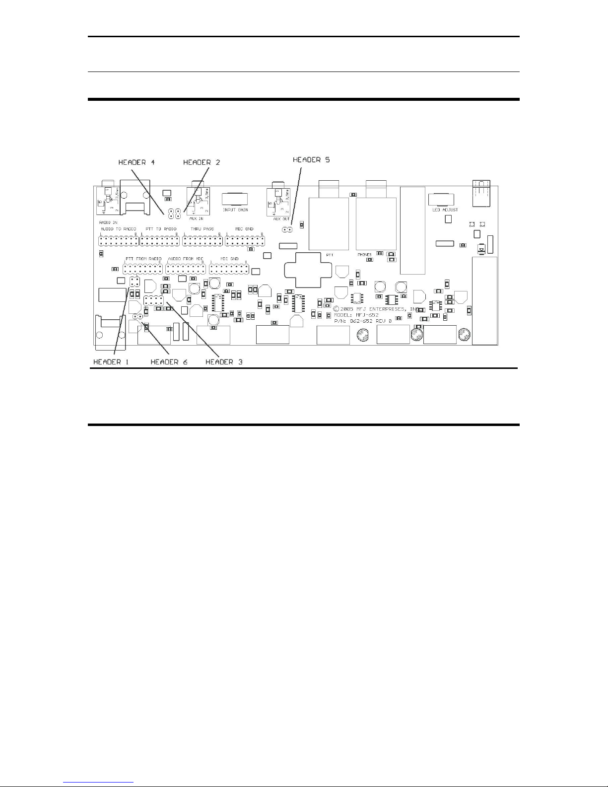
INTERNAL JUMPER BLOCKS
The Jumper Installation diagrams within this instruction manual will help you in
setting up your MFJ-652 to match your radio. If your radio is not listed with the
diagram, it means that we have not verified your radio to use that diagram. You
can try to install jumpers as indicated. If that does not work, please refer to the
radio manual to identify the MIC pin assignment for you radio then follow the
instructions given at the end of this section in the MFJ-652 instruction manual to
install the jumpers.
Refer to this figure for the pin numbering 1-8 on the
internal jumper blocks. The RJ-45 connector is
numbered with the clip down. Note the position of the
key for the 8 pin round mic jack this could be rotated in
your particular unit.
ICOM 8-Pin Round Microphone Setup:
IC-255, 288, 28, 290, 38A, 375, 707, 718, 725, 726, 728, 729, 730, 735, 737, 745, 746,
746PRO, 751, IC-756, 756PRO, 756PROII, 775DSP, 761, 78, 781, 910H
This diagram may cover
some other radios in the
ICOM product line with 8-pin
round microphone jack.
If there are any Questions
concerning the information
provided, please refer to
your RADIO INSTRUCTION
MANUAL.
MFJ is neither liable nor
responsible for any mistakes
or errors in the information
provided.
Receive Audio is taken from
the Headphone Audio
Output.
Figure 5: ICOM 8-Pin Round Microphone Setup