MFZ Ovitor TVR(FC) 5 Manual

OPERATING AND MAINTENANCE INSTRUCTIONS
DOOR OPERATOR TVR(FC) 5
OVITOR OY
SIENITIE 24
FIN‐00760 HELSINKI
FINLAND
Tel. +358 (0) 207 106 600
Fax. +358 (0) 207 106 601
ENG
2 ‐Door operator TVR(FC) 5 / Rev 1.41
1. CONTENT
2. KEY TO SYMBOLS
3. GENERAL INFORMATION
These operang instrucons are part of the door operator
delivery. Always store these instrucons in the vicinity of
the door operator, e.g. with other technical documents of
the door.
Anyone involved in installing, maintaining or repairing the
door operator must be familiar with this manual and ob‐
serve its regulaons and instrucons. The manufacturer will
not take responsibility for damage and operaonal errors
that occur if the regulaons and instrucons contained or
menoned in this manual are neglected.
The door operator described in these operang instrucons
is meant to open and close a door or similar. The door oper‐
ator is described here on the basis of its technical character‐
iscs at the me of prinng the manual.
The manufacturer reserved the right to modify separate
basic unit assembly groups and materials if these modifica‐
ons are considered appropriate for improving the capacity
and safety of the door operator.
The speed and travel of the door determine which gear and
limit transmission values should be used. Different possible
transmission raos are not explained in this manual. The
transmissions for each specific case can be found in the pro‐
ducon informaon, by the serial number.
Serial number:
Fig. 1.
1. Contents ................................................................ 2
2. Key to symbols ...................................................... 2
3. General informaon.............................................. 2
3.1 Safety instrucons ........................................... 3
3.2 Rang plate ..................................................... 3
4. Product range ....................................................... 4
4.1 Opons ............................................................ 4
5. Mechanical installaon ......................................... 4
6. Electrical installaon ............................................. 5
7. Set up .................................................................... 6
7.1 Adjustment of the slipping clutch .................... 6
7.2 Adjustment of the limits .................................. 6
7.3 Digital seng –AVE limits ............................... 7
8. Operaon .............................................................. 8
8.1 Disengagement clutch (not TVR‐type) ............ 8
9. Service and maintenance ...................................... 8
9.1 Changing the fricon lining of the
slipping clutch ....................................................... 9
9.2 Permied load ................................................. 9
9.2 Spare parts ...................................................... 9
9.3 Troubleshoong .............................................. 9
10. Declaraon of incorporaon of partly
completed machinery .........................................12
Danger of personal injury!
The safety instrucons must be
observed
Warning! Danger to property!
The safety instrucons must be
observed!
Informaon
Special informaon
Reference to other sources of
informaon

Door operator TVR(FC) 5 / Rev 1.41 ‐ 3
This door operator meets the requirements of 2006/42/EY,
EMC‐direcve 2004/108/EY, LVD 2006/108/EY and standard
EN 13241‐1 and is delivered in safe operaon mode. Self‐
made modificaons that could affect the operaonal safety
of the door operator are not allowed.
Observing the instrucons will improve your safety and that
of your operang environment. It also ensures the opera‐
onal safety of the door and its drive unit and prevents in‐
terrupons in use caused by faulty handling, along with bur‐
dens to the environment.
Observe occupaonal safety and environmental protecon
regulaons, when transporng, seng‐up, installing, oper‐
ang, maintaining and dismantling the door operator.
To ensure operaonal safety, only original components or
parts that have been specifically approved by the manufac‐
turer may be used in or connected to the door operator. All
components of the device have been selected, protected
and constructed so that they are durable and meet the envi‐
ronmental and operaonal requirements specified in this
manual.
Perform maintenance on the door and the door operator
only when the door is not moving. To prevent unintenonal
starng of the door operator, you must e.g. lock the main
switch of the door operator control system in the 0 posion.
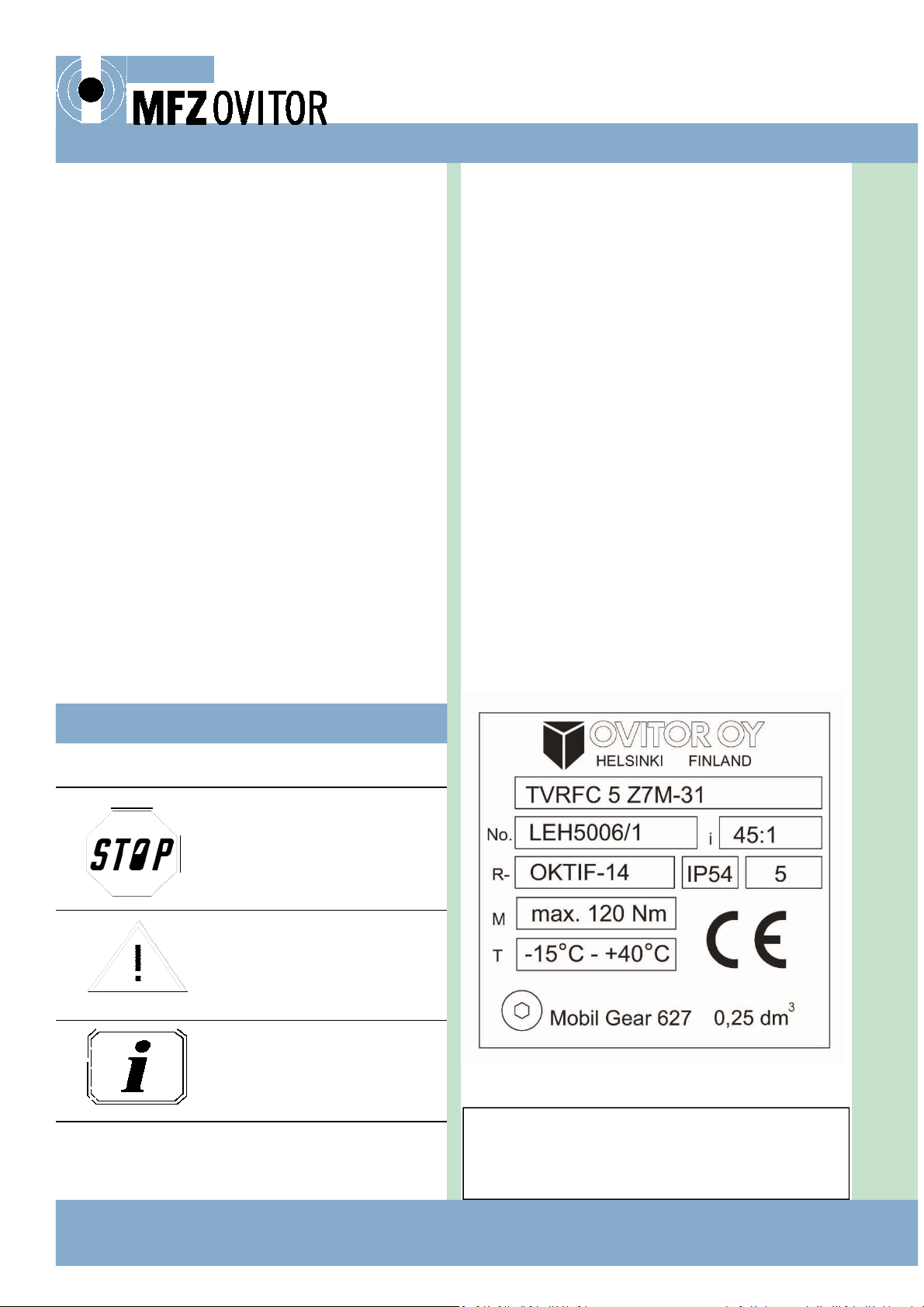
3.2 RATING PLATE
Every complete drive unit has two (2) rang plates, one on
the gear box and the other one on the electric motor (fig. 2).
The plate on the gear box shows (fig. 1), in addion to the
technical informaon, also the producon serial number
(e.g. MLN9878/1), on the basis of which all original produc‐
on informaon can be traced later.
Only authorised and properly trained
personnel may install, maintain or
repair the door operator. In cases of
more demanding repairs, always de‐
liver the door operator to the manu‐
facturer for maintenance.
Ensure that the persons responsible
for installaon, preparaon for uli‐
saon and maintenance of the door
operator have read this manual and
that they understand and observe the
regulaons and instrucons con‐
tained and menoned therein.
3.1 SAFETY INSTRUCTIONS In all quesons related to service, spare part deliveries or
claims it is extremely important to refer to the serial num‐
ber. With reference to this number it will be possible to
clear up in detail important maers related to producon,
quality control and deliveries. Record the serial number of
the GEAR box e.g. on the second page of this manual.
Fig. 2.
Rang plate of the
motor
Rang plate
of the gear
Mounng 4xM8—
dep. 20
4 ‐Door operator TVR(FC) 5 / Rev 1.41
4. PRODUCT RANGE
4.1 OPTIONS
TVR 5 door operator is delivered in following opons:
F = Disengagement clutch for manual operaon
C = Slipping clutch, dry, on the input sha between motor
and the gear box
Type of the mounng flange:
Z6 = flange IEC 63 B5
Z7 = Flange IEC 71 B5
Z8 = Flange IEC 80 B5
Z9 = Flange IEC 90 B5
X = Flange for Ovitor brake motor, not IEC standard
Type of motor:
M = 3~ electric motor
MY = 1~ electric motor
MD = Dahlander 2‐speed motor
MJ = Motor with built‐in magnec brake (Brake motor)
MDJ = Dahlander 2‐speed brake motor
MT = DC‐motor
E.g. TVRFC 5 Z7M
5. MECHANICAL INSTALLATION
Before installaon, inspect the drive unit visually for possi‐
ble damage sustained during transport. Addionally, the
drive unit must stand on each of its four sides for about one
minute to make sure that no damage to rotary sha seals or
the housing has been sustained during transport. No oil
leaks are allowed. If oil is leaking out, remove it immediately
with an oil‐absorbing substance. Installaon of a drive unit
with oil leaks is forbidden. Deliver a faulty unit to the manu‐
facturer for repair.
The drive unit must be mounted carefully on a solid and
even surface and bolted firmly to the base. If the drive unit
is to be mounted on a steel structure, make sure that this
structure will not bend. If the mounng base is not perfectly
even, the fixing lugs of the drive unit could break when the
fixing screws are ghtened. Do not bend gear when ghten‐
ing the fixing screws. Use fixing screws with a min. strength
class of 8.8. Install the drive unit so that no resonance vibra‐
on will occur and no vibraon can be transferred from ad‐
jacent structures. Do not perform welding on the drive unit
or connect it to welding circuit.
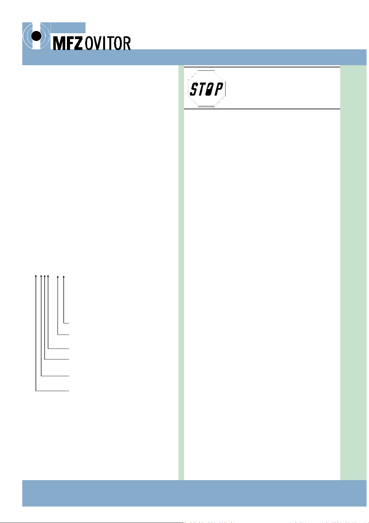
When mounng the drive unit, note the access required for
adjustment of the limit switches, as shown in the adjacent
fig. 2. The dimensions of the drive unit are shown in type
specific drawings 62XX/7XXX (e.g. 6225/7076).
If a chain transmission is used, sprockets should be perfectly
aligned. The fixing of the drive unit must be able to support
min. 5000 N chain tension.
Drive unit must be sheltered against falling objects.
If the drive unit has been detached, e.g. for maintenance, it
must be mounted again using instrucons given above. The
drive unit must be detached, together with its motor. In
cases where more demanding repairs are required, always
deliver the door operator to the manufacturer for mainte‐
nance. An exploded view of the drive unit and the part num‐
bers can be found later in this manual.
Type of motor
Mounng flange of the motor
Slipping clutch on the input sha
Disengagement clutch
Limit switches
Hollow sha worm gear
Only properly authorised and
trained personnel may dismantle or
repair the door operator.
Door operator TVR(FC) 5 / Rev 1.41 ‐ 5
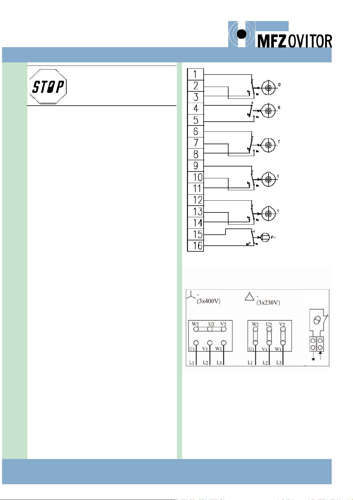
6. ELECTRICAL INSTALLATION
Perform the installaon and make the connecons accord‐
ing to the wiring and circuit diagrams provided specifically
for this case by control system supplier.
The temperature detectors of the gear unit, the possible
micro switch of the disengagement clutch and the micro
switches of the limits are already connected to the connect‐
ors in the limit switch box according to the fig. 3. Do not
modify these connecons without first consulng the manu‐
facturer.
Open and close the cover of the limit switch box carefully so
that its enclosure class will not decrease in installaon. First
loosen the fixing bolt of the cable gland lead‐through (part
number 569) on the side of the limit switch box. Then loos‐
en all fixing bolts of the cover (1/2 turn) crosswise. Aer
that loosen the bolts completely and take off the cover. In‐
stall the limit cable in the cable gland and ghten it. Check
the cable’s sealing. Make the necessary connecons.
Aer checking the adjustment and operaon of the limit
switches, install the cover of the limit switch box in its place.
Check that the sealing on the gear unit’s side has not
suffered damage during the installaon. Check that no dirt
remains between the cover and the gear unit. If there is a
disengagement mechanism (F) in the gear unit, check that
the slot in the end of the disengagement sha is in the cor‐
rect posion with respect to the shoulder inside the disen‐
gagement lever. If the parts do not match, the cover cannot
be posioned correctly and could be damaged when the
fixing bolts are ghtened. When the cover is correctly in
place, ghten the fixing bolts evenly. Also ghten the fixing
bolt in the cable gland lead‐through. Aer ghtening the
bolts, check that the lever of the disengagement clutch
funcons properly. The lever must turn 90 degrees.
Fig. 4.
Only properly authorised and
trained personnel is allowed to car‐
ry out electrical installaon.
connecon connecon Terminal for
thermal trip
in motor
winding
Control current
Fig. 3. Connecon example OKTIIF
(GREEN)
(WHITE)
(YELLOW)
(RED)
(RED)
DISENGAGEMENT

6 ‐Door operator TVR(FC) 5 / Rev 1.41
7. SET UP
7.1 ADJUSTMENT OF THE SLIPPING CLUTCH
The torque transmied by the drive unit must always be
adjusted in due consideraon of the safety requirements of
the door operaon. The limitaon of the torque is done by
adjusng the slipping clutch situated between the electric
motor and the gear box. When delivered from the factory
the slipping clutch is le loose so that no torque can be
transmied from the electric motor.
Adjustment:
1. Loosen the M8 lock nut at the end of the worm sha.
2. Hold the worm sha with a spanner.
3. Start turning the adjustment screw inwards (= clockwise)
unl the required torque has been obtained.
The torque should be adjusted so that it is just high enough
to move the door over its complete travel and low enough
to permit the clutch to slip as soon as the door is obstructed
in its movement. A direct safety risk is produced if the
torque is set to a considerably higher level than required for
the door operaon.
7.2 ADJUSTMENT OF THE LIMIT SWITCHES
To ensure correct adjustment, familiarise yourself with the
funconing of the limits in the control system. For further
informaon of the limit switches, check the documentaon
of the control system.
Limit switches are adjusted as shown in fig. 6.
1. The limit switches are adjusted with the locking screw
(N) and fine adjustment screw (M) (Allen key size:2.5
mm).
2. First turn the cam wheel near to the right posion and
ghten the locking screw (N).
3. Fine adjustment can be done by screwing the adjustment
screw (M).
Adjustment of the doors limit posions.
1. Move the door manually to the posion that corre‐
sponds the acvaon posion of the limit switch.
2. Adjust the cam wheel to its correct posion (micro
switch is near to acvaon). Note the rotaon direcon
of the limit sha!
3. It is recommended to perform the final fine adjustment
by operang the door with the drive unit.
4. Check the proper operaon of all protecve and external
devices.
Fig. 6. Adjustment of the limit switches
Fig. 5. Slipping clutch
Safety regulaons state that the door
movement must not produce a pressing
force exceeding 800 N. If the door can‐
not be moved by hand, due to a fault in
the counterbalancing or for some other
reason, it is not permied to adjust the
slipping clutch to a higher torque. The
reason for the incorrect operaon must
be removed or corrected.
Before starng to adjust the slipping
clutch, check and make sure that the
door can easily be moved manually in
every part of its travel.
Slipping
clutch lining
Worm sha
Lock nut (M8)
Adjustment screw for
torque of slipping clutch
Door operator TVR(FC) 5 / Rev 1.41 ‐ 7
7.3. DIGITAL SETTINGS ‐LIMIT SWITCH AND SAFE‐
TY CIRCUIT FOR DRIVE
Informaon!
Please refer to the control unit’s oper‐
ang manual for instrucons on seng
the end posions.
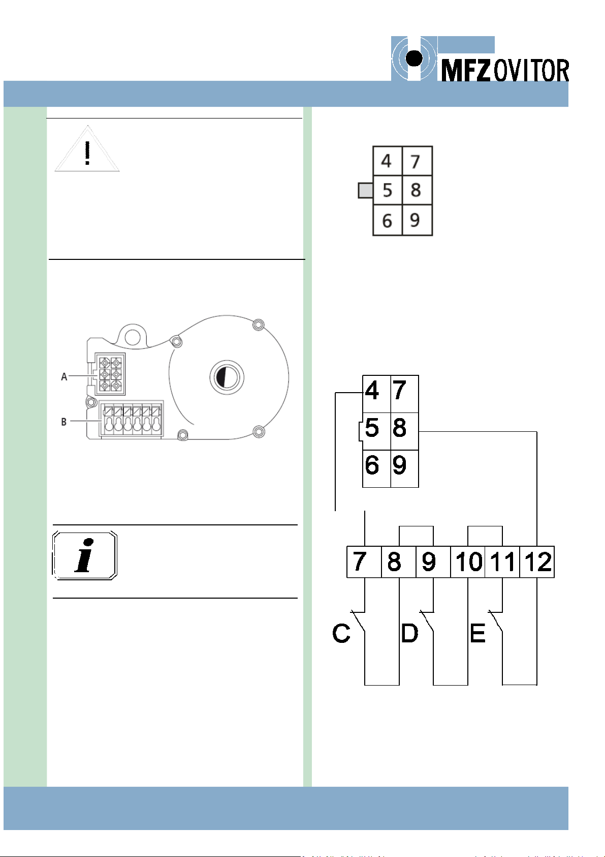
Wiring allocaon
The numbers on the plug are also the wire numbers:
4: Safety circuit input
5: RS485B
6: GND
7: RS485A
8: Safety circuit output
9: 7...18 VDC
AVE (absolute value encoder) plug terminal (7‐12)
C. Thermal element in the drive
D. Manual emergency control (crank or chain)
E. Disengagement
Electric interface
A: AVE plug (absolute value encoder plug)
B: AVE plug terminal (absolute value encoder plug
terminal)
At the inial installaon phase, the rota‐
on direcon of the electric motor can
be wrong.
Be prepared to stop the movement to
wrong direcon immediately by using
the STOP buon.
Interchange two phase conductors to
change the rotaon direcon. It is rec‐
ommended to make the change in the
control unit.
8 ‐Door operator TVR(FC) 5 / Rev 1.41
8. OPERATION
Conduct weekly inspecons to determine changes in the
sounds of the gear unit or oil leaks from the gear unit. If you
note oil leaks or unusual sounds during drive unit operaon,
stop the drive immediately and make sure that it cannot be
used. If you cannot determine the cause of the problem,
deliver the drive unit to the manufacturer for repair.
Note that dust may accumulate on the drive unit during its
operaon. If necessary, clean the drive unit regularly. The
dust layer must not be thicker than 5 mm. Do not use high‐
pressure cleaning machines to clean the drive unit.
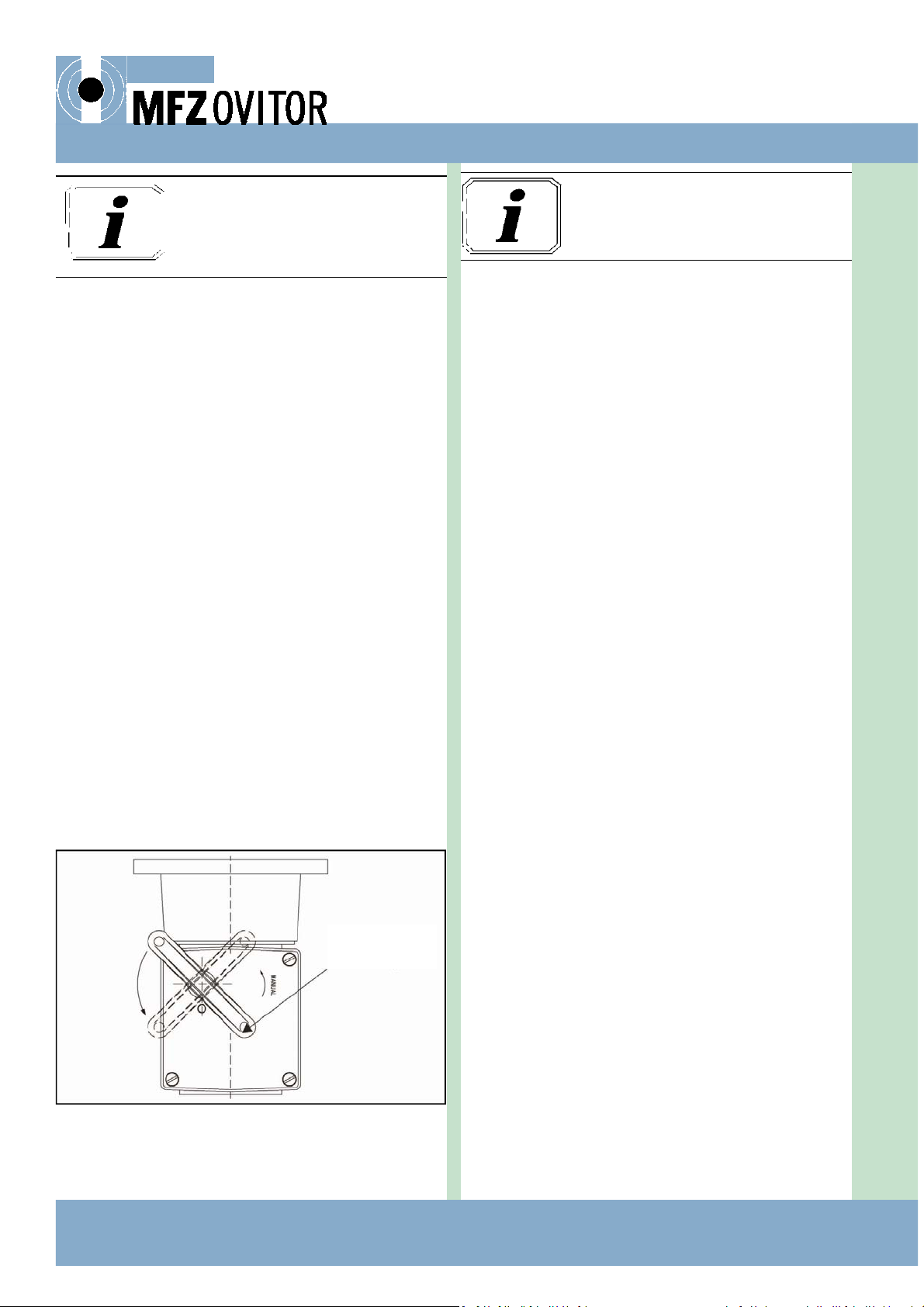
8.1 DISENGAGEMENT CLUTCH (NOT TVR TYPE)
Disconnecon of the drive unit is done by turning the disen‐
gagement lever. This enables the manual operaon of the
door. To disengage, turn the lever of the clutch 90 degrees,
as shown in fig. 7. For operaon of the lever from floor level,
aach ropes to the holes at the ends of the lever.
The movement of the lever affects a micro switch. While
affected, the micro switch disconnects the control current.
For normal electric operaon, move the lever back to its
original posion.
Note! Switching back to electric operaon is allowed only by
turning the disengagement lever to its posion for electric
operaon and by moving the door manually unl the clutch
dogs are engaged perfectly (→click).
Fig. 7. Disengagement clutch
9. SERVICE AND MAINTENANCE
All service and maintenance work must be carried out care‐
fully and only by thoroughly trained personnel. Perform
maintenance of the door and the door operator only when
the door is not moving. To prevent unintenonal staring of
the door operator, lock the main switch of the control sys‐
tem in the 0 posion.
Semi‐annual service and maintenance:
Check the condion and adjustment of the slipping
clutch
Check the ghtness of all fixing bolts in the gear unit and
the electric motor.
If a chain is used in power transmission, check the align‐
ment of the sprockets.
Check the condion of the chain and the sprockets.
Examine the condion of the gear unit visually.
Check the sounds of the gear unit.
Check the ghtness of the gear unit.
Remove the dust that has accumulated on the gear unit
and the motor.
In addion to this, check the condion of the enre gear
every three years.
Correct lubricaon is of primary importance for the func‐
oning of a worm gear. The oil grade for the inial filling is
shown on the rang plate. In the specified operang condi‐
ons, oil changes are not necessary. The oil quanty should,
however, be checked at the me of installaon and at least
once a year during normal maintenance of the door.
The inial filling oil used is suitable for an environment with
temperature variaons from –20 oC to +40 oC. For drive
units that are run with an especially high operang frequen‐
cy such that the surface temperature of the unit is constant‐
ly above +40oC, oil changes are recommended. In such oper‐
ang condions, the first oil change should occur aer ap‐
prox. six months of operaon and subsequently at three
year intervals.
When changing the oil, always use the same type of oil used
previously. It is not allowed to mix oils of different types or
from different manufacturers. Mixing oil types may damage
the rotary sha seals and cause oil leaks
When changing the oil, please note that hot oil may cause
burns. Always use protecve gloves and remove leaking oil
immediately with an oil‐absorbing substance.
Observe the regulaons and instruc‐
ons given in this manual when oper‐
ang the door.
Disengagement
lever
Please note the instrucons in the
”Operaon” secon for observing gear
unit condion.

Door operator TVR(FC) 5 / Rev 1.41 ‐ 9
Fig. 8. Gear side of the clutch and the fricon lining
9.1 CHANGING THE FRICTION LINING OF THE
SLIPPING CLUTCH
Changing the fricon lining of the slipping clutch is the only
special service operaon required. The operaon is done as
follows:
1. Check the thickness of the fricon lining of the slipping
clutch through inspecon hole in the side of the
mounng flange between the gear box and the electric
motor. The inspecon hole is covered with a detachable
plasc plug. If the fricon lining is worn out, carry out
points 2‐6.
2. Unscrew the adjustment screw fully (fig. 5)
3. Detach the motor from the gear
4. The gear side of the clutch has a guide for the correct
alignment of the fricon lining. Make sure the new fric‐
on lining is aligned correctly.
5. Aach the motor with the gear
6. Adjust the slipping clutch according to chapter 7.1
4
9.2 PERMITTED LOAD
The door operator’s maximum permied torque has been
informed in the rang plate. It is not allowed to connect the
door operator to drive a mechanism, the operaon of which
would, e.g. through ineral forces, exert on the output sha
of the gear a torque exceeding the permied maximum
torque.
The permied service life of the door operator is 12 000
operang hours with the maximum permied nominal out‐
put of the electric motor.
9.3 SPARE PARTS
Every separate component manufactured by Ovitor Oy has a
part number composed of three or dour digits. When order‐
ing spare parts, always menon the serial number of the
drive unit (on the gear unit rang plate) and the part num‐
ber shown in the drawing. With the help of the serial num‐
ber, it is possible to determine the correct part from the
producon informaon of the gear unit.
9.4 FAULT TRACING
Very oen, faults in electric door operaon originate from
devices connected to the control system (e.g. from align‐
ment of photo cells). First find out whether the fault is in
the door’s construcon, in the control systems or in the
drive unit.
Turn the disengagement lever of the gear unit to manual po‐
sion and check that the door can be easily moved manually
in both direcons over the complete travel of the door. If
the door cannot be moved at all, the fault may be in the dis‐
engagement mechanism. If the door moves only heavily, the
fault is in the door’s construcon or in its balancing arrange‐
ments. In this case, the door itself must be repaired
If the door can be moved manually, move it to half‐open po‐
sion and turn the lever of the disengagement mechanism
to its electric operaon posion. Move the door manually so
that the clutch dogs are perfectly engaged. Drive the door in
the opening and closing direcons. If the door does not
move in one or both direcons, the fault is probably in the
control system. However, if the electric motor is running but
the output sha of the gear unit is not rotang, the fault is
in the disengagement mechanism of the gear unit.
If the drive unit is not equipped with a disengagement
clutch (type TVR), the door must be released for manual op‐
eraon by some other means so that the movement of the
door can be checked.
If the fault is in the control system, please refer to the con‐
trol system documentaon.
If the fault is in the drive unit, please refer to the following
table.
9. SERVICE AND MAINTENANCE

10 ‐Door operator TVR(FC) 5 / Rev 1.41
9. SERVICE AND MAINTENANCE
Manifestaon Fault Acon
Loud sounds from the fixing point of the
gear unit
Fixing of the gear unit is loose Tighten the fixing bolts; if they are damaged, replace
Unusual sounds from the gear unit Damage to the worm sha or wheel Contact the manufacturer
Unusual sounds from the gear unit Damage to the bearings Contact the manufacturer or replace the bearing
Unusual sounds from the gear unit Not enough oil Check the oil quanty, add more if necessary; find out the
reason for diminished oil quanty, check for possible oil leaks
Vibraon of input sha at the bearing point Damage to the bearing Contact the manufacturer or replace the bearing
Unusual sounds from the drive motor Refer to the documentaon provided by the drive motor
supplier
Thermal protecon of the gear unit stops
the drive unit
Door’s resistance to moon has increased Check the condion of the door and its fixings
Thermal protecon of the gear unit stops
the drive unit
Not enough oil Check the oil quanty, add more if necessary; find out the
reason for diminished oil quanty, check for possible oil leaks
Thermal protecon of the gear unit stops
the drive unit
Damage to the worm sha or wheel Contact the manufacturer
Oil leak from the gear unit frame Mechanical damage in the gear housing Contact the manufacturer
Oil leak from the gear unit frame Fixing bolts of the gear unit halves are loose Check and ghten the fixing bolts
Oil leak from the rotary sha seal Seal has worn out or there is dirt between the
seal and the sha
Contact the manufacturer or check the rotary sha seal and
replace it if necessary
Disengagement mechanism doesn’t work Gear locked when the door was driven with
force against an inelasc obstacle
Rotate the input sha of the gear unit e.g. from the side of
the electric motor
Disengagement mechanism doesn’t work Disengagement mechanism has been damaged Contact the manufacturer
Place where door travel stops has changed Adjustment of the limit switches has changed Check that the adjustment ghtness of the limit cams has not
decreased. Tighten and adjust the limits again.
Limit switches do not stop the door Limit sha is damaged or does not rotate Contact the manufacturer
Limit switches do not stop the door Micro switch for the limit does not funcon Replace the limit switch
Clack between the gear and motor Flexible clutch worn out Replace the clutch
The motor runs, but gear sha is not turn‐
ing
Slipping clutch is slipping Adjust or replace the slipping clutch

Door operator TVR(FC) 5 / Rev 1.41 ‐ 11

12 ‐Door operator TVR(FC) 5 / Rev 1.41
10. DECLARATION OF INCORPORATION OF PARTLY COMPLETED MACHINERY
DECLARATION OF INCORPORATION OF PARTLY COMPLETED MACHINERY
Ovitor Oy
Sienie 24
00760 Helsinki
Finland
Descripon and idenficaon of the partly completed machinery:
Door operator TVR(FC) 5 with various limit and gear transmissions
The essenal requirements of EC Machinery Direcve 2006/42/EC have been applied and fulfilled for the above menoned
machinery to be used with industrial doors, gates and barriers. The relevant technical documentaon has been compiled in
accordance with Annex VII, Part B of EC Machinery Direcve 2006/42/EC.
In addion the partly completed machinery is in conformity with the EC 2006/95/EC Low Voltage Direcve LVD, 2004/108/
EC Electromagnec Compability EMC and 2002/95/EC the Restricon of the use of certain Hazardous Substances in Electri‐
cal and Electronic Equipment RoHS.
The above listed products are delivered according to the following standards to the extent to which they may be applicable:
EN ISO 12100:2010, EN 60204‐1+A1+AC, EN 60335‐1+A11+AC, EN‐55014‐1+A1, EN 61000‐3‐
2+A1+A2, EN 61000‐3‐3, EN 61000‐6‐2, EN61000‐6‐3+A1, EN 61439‐1, EN 61439‐3, EN 60529+A1,
EN 13241‐1+A1, EN 60335‐2‐103, EN 13241+A1, EN 12453, EN 12445, EN 12604, EN 12605, EN
12978+A1
SFS‐Inspecta Serfioin OY has issued a cerficate ascertaining that the manufacturer's quality system meets the require‐
ments of standard SFS‐EN ISO 9001:2008 and the general guidelines ABC 200, cerficate 1229‐06.
We undertake, in response to a reasoned request, to supply it in electronic form to the market surveillance authories with‐
in a reasonable period.
The party authorized to compile the technical documentaon is:
Ovitor Oy / Engineering Manager
Sienie 24
00760 Helsinki
Finland
The devices are not intended to funcon independently but as a part of an electrically operated machine. In the design, con‐
strucon and servicing of the machinery, it must be ensured that the loads to which the door mechanism is subjected do not
exceed the values given in the instrucon manual of the mechanism, and that the permied service life of a door mecha‐
nism is no more than 12 000 operang hours. As regards the installaon, sengs and servicing of the machinery, the in‐
strucons issued by us for the type of installaon in queson must be observed.
The partly completed machinery must not be put into service unl the final machinery into which it is to be incorporated has
been declared in conformity with the provisions of the Machinery Direcve.
Helsinki, 14th of September 2016
_______________
Juha‐Ma Lyhykäinen
Producon Manager
Ovitor Oy
Table of contents
Other MFZ Ovitor Garage Door Opener manuals


Popular Garage Door Opener manuals by other brands


Henderson
Henderson Magic 600 operating manual

Novoferm
Novoferm Novomatic 403 Installation, operating and maintenance instructions

Raynor
Raynor Commander II Safety Signal 3240RGD owner's manual

Casanoov
Casanoov BUNKER B500 manual

ABON
ABON Ultra S Installation and operating instructions

moore o matic
moore o matic XX325 Assembly and installation instructions

Chamberlain
Chamberlain LiftMaster MJ5011U installation manual

Chamberlain
Chamberlain Series 1000E owner's manual

Chamberlain
Chamberlain Power Drive 3132E owner's manual

Nice
Nice AVIO500 Instructions and warnings for installation and use

Chamberlain
Chamberlain Grifco eDrive instructions

Chamberlain
Chamberlain T installation manual