Black 0002
Black0002
CONTENTS
INSTALLATION TOOLS REQUIRED
INSTALLATION PREPARATION
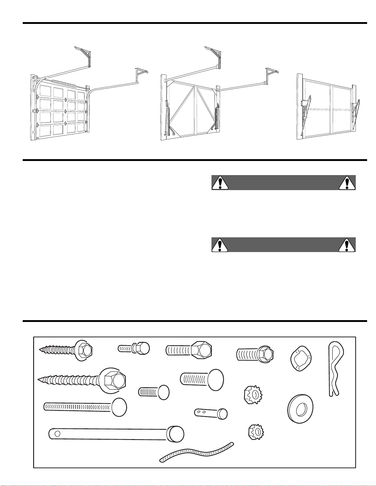
GARAGE DOOR TYPES
. . . . . . . . . . . . . . . . . . . . . . . . . . 1
CHECK DOOR BALANCE
. . . . . . . . . . . . . . . . . . . . . . . . . 1
HARDWARE IDENTIFICATION
. . . . . . . . . . . . . . . . . . . . . 1
OPERATOR PARTS IDENTIFICATION
. . . . . . . . . . . . . . . 2
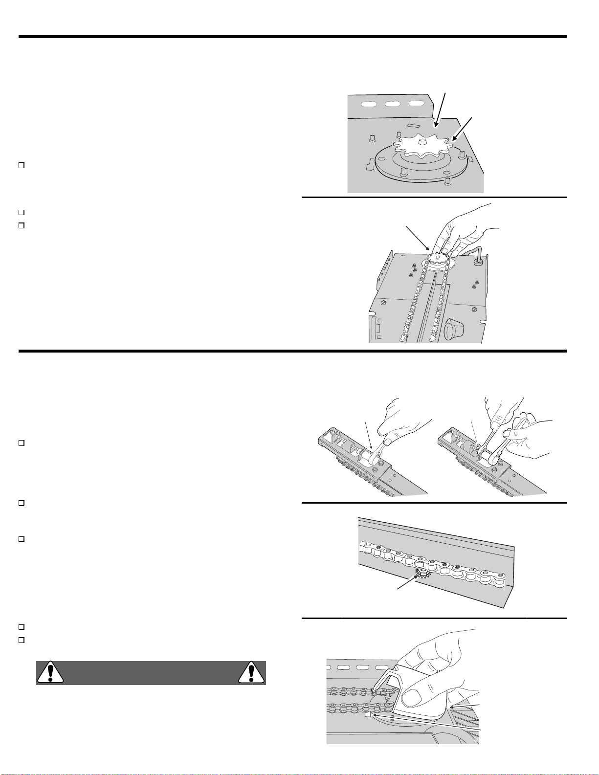
OPERATOR PRE-ASSEMBLY
ASSEMBLY STEP 1
. . . . . . . . . . . . . . . . . . . . . . . . . . . . . . 3
Attaching Rail to Operator . . . . . . . . . . . . . . . . . . . . . . . 3
ASSEMBLY STEP 2
. . . . . . . . . . . . . . . . . . . . . . . . . . . . . . 4
Attaching Chain to Sprocket. . . . . . . . . . . . . . . . . . . . . . 4
ASSEMBLY STEP 3
. . . . . . . . . . . . . . . . . . . . . . . . . . . . . . 4
Adjusting Chain and Installing Sprocket Cover . . . . . . . 4
OPERATOR INSTALLATION
INSTALLATION STEP 1A
. . . . . . . . . . . . . . . . . . . . . . . . . . 6
Sectional Door and One-piece Track Door Header
Bracket Location. . . . . . . . . . . . . . . . . . . . . . . . . . . . . . . 6
INSTALLATION STEP 1B
. . . . . . . . . . . . . . . . . . . . . . . . . . 7
One-piece Door without Track Header
Bracket Location. . . . . . . . . . . . . . . . . . . . . . . . . . . . . . . 7
INSTALLATION STEP 2
. . . . . . . . . . . . . . . . . . . . . . . . . . . 8
Installing the Header Bracket . . . . . . . . . . . . . . . . . . . . . 8
INSTALLATION STEP 3
. . . . . . . . . . . . . . . . . . . . . . . . . . . 9
Connecting Rail to the Header Bracket . . . . . . . . . . . . . 9
INSTALLATION STEP 4
. . . . . . . . . . . . . . . . . . . . . . . . . . 10
Positioning the Operator. . . . . . . . . . . . . . . . . . . . . . . . 10
INSTALLATION STEP 5
. . . . . . . . . . . . . . . . . . . . . . . . . 11
Hanging the Operator . . . . . . . . . . . . . . . . . . . . . . . . . 11
INSTALLATION STEP 6
. . . . . . . . . . . . . . . . . . . . . . . . . 12
Installing the Pushbutton. . . . . . . . . . . . . . . . . . . . . . . 12
INSTALLATION STEP 7
. . . . . . . . . . . . . . . . . . . . . . . . . 13
Installing the Lens Cover and Light Bulb. . . . . . . . . . . 13
INSTALLATION STEP 8
. . . . . . . . . . . . . . . . . . . . . . . . . 13
Attaching the Trolley Release Handle. . . . . . . . . . . . . 13
INSTALLATION STEP 9
. . . . . . . . . . . . . . . . . . . . . . . . . 14
Installing the DoorSentry Infrared Safety Beam . . . . . 14
INSTALLATION STEP 10
. . . . . . . . . . . . . . . . . . . . . . . . 15
Wiring the DoorSentry Infrared Safety Beam . . . . . . . 15
INSTALLATION STEP 11A
. . . . . . . . . . . . . . . . . . . . . . . 16
Sectional Door, Door Bracket and Door Arm
Installation. . . . . . . . . . . . . . . . . . . . . . . . . . . . . . . . . . 16
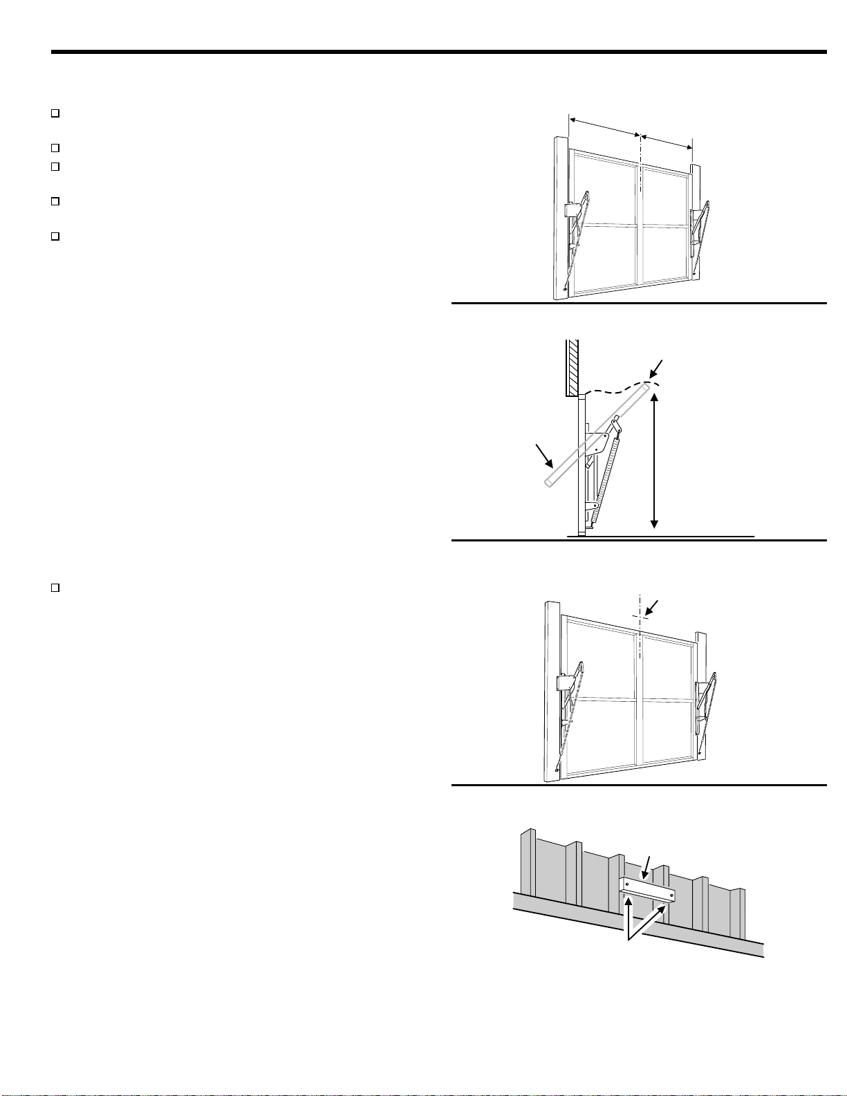
INSTALLATION STEP 11B
. . . . . . . . . . . . . . . . . . . . . . . 17
One-piece Doors (With and Without Track), Door
Bracket and Door Arm Installation. . . . . . . . . . . . . . . . 17
INSTALLATION STEP 12
. . . . . . . . . . . . . . . . . . . . . . . . 18
Connecting Operator to Power Source . . . . . . . . . . . . 18
OPERATOR ADJUSTMENTS
ADJUSTMENT STEP 1
. . . . . . . . . . . . . . . . . . . . . . . . . . 19
Aligning the DoorSentry Infrared Safety Beam. . . . . . 19
ADJUSTMENT STEP 2
. . . . . . . . . . . . . . . . . . . . . . . . . . 20
Testing the Radio Remote Control . . . . . . . . . . . . . . . 20
Programming the receiver. . . . . . . . . . . . . . . . . . . . . . 20
ADJUSTMENT STEP 3
. . . . . . . . . . . . . . . . . . . . . . . . . . . 21
Setting the Up and Down Limits. . . . . . . . . . . . . . . . . . 21
ADJUSTMENT STEP 4
. . . . . . . . . . . . . . . . . . . . . . . . . . . 22
Adjusting the Door Force . . . . . . . . . . . . . . . . . . . . . . . 22
USER INFORMATION
USER INSTRUCTIONS 1
. . . . . . . . . . . . . . . . . . . . . . . . . 23
Using the Garage Door Operator. . . . . . . . . . . . . . . . . 23
USER INSTRUCTIONS 2
. . . . . . . . . . . . . . . . . . . . . . . . . 24
Care for the Garage Door Operator. . . . . . . . . . . . . . . 24
OPERATOR ACCESSORIES
. . . . . . . . . . . . . . . . . . . . . . 25
SERVICE INFORMATION
REPLACEMENT PARTS LIST
. . . . . . . . . . . . . . . . . . . . . 26
T-Rail . . . . . . . . . . . . . . . . . . . . . . . . . . . . . . . . . . . . . . 26
REPLACEMENT PARTS LIST
. . . . . . . . . . . . . . . . . . . . . 27
Operator Head . . . . . . . . . . . . . . . . . . . . . . . . . . . . . . . 27
INDEX
. . . . . . . . . . . . . . . . . . . . . . . . . . . . . . . . . . . . . . . . 28
TROUBLE SHOOTING TABLE
. . . . . . . . . . . . . . . . . . . . 29
LIMITED WARRANTY
. . . . . . . . . . . . . . . . . . . . . . . . . . . 30
IMPORTANT SAFETY NOTES
Please read the instructions carefully! This garage door
operator is designed to provide safe and reliable service if
installed and tested as described in this manual. A garage door
is the largest mechanical appliance in a residence. Care must
be taken to prevent injury or death during installation and
operation of the garage door and garage door operator.
The following formats are used for safety notes in this manual:
WARNING
This type of warning note is used to
indicatepossiblemechanicalhazardsthat
may cause serious injuries or death.
WARNING
This type of warning note is used to
indicatepossibleelectricalshockhazards
that may cause serious injuries or death.
CAUTION
This type of warning note is used to
indicate the possibility of damage to the
garage door or garage door operator.
Hammer
Pliers
Wire Cutter
7/16", 1/2" and 9/16" Sockets
and Wrench
Phillips Head
Screwdriver Flat Head Screwdriver
Drill
3/16" and 1/4" Bits
Tape Measure
Step Ladder 1/2", 7/16" and 9/16"
Open End Wrenches
Short
Socket Extension