MG Energy Systems RS Series User manual
MG Energy Systems B.V. | Foeke Sjoerdswei 3 | 8914 BH Leeuwarden | The Netherlands
Innovation in energy storage
Lithium-Ion RS series battery module
- Manual -
MGRS12S4P176-300, MGRS14S3P132-300, MGRS16S3P132-300, MGRS24S2P088-300,
MGRS12S4P176-500, MGRS14S3P132-500, MGRS16S3P132-500, MGRS24S2P088-500,
MG Energy Systems B.V.
Revision: 2.8
Date: 10-06-2020

MG Energy Systems B.V. | Foeke Sjoerdswei 3 | 8914 BH Leeuwarden | The Netherlands
Innovation in energy storage
Copyrights 2020 MG Energy Systems B.V.
All Rights Reserved
This publication or parts thereof, may not be reproduced in any form, by any method, for any
purpose.
For conditions of use and permission to use this manual for publication in other than the English
language, contact MG Energy Systems B.V..
MG ENERGY SYSTEMS B.V. MAKES NO WARRANTY, EITHER EXPESSED OR IMPLIED, INCLUDING BUT
NOT LIMITED TO ANY IMPLIED WARRANTIES OF MERCHANTABILITY OR FITNESS FOR A PARTICULAR
PURPOSE, REGARDING THESE MG ENERGY SYSTEMS B.V. PRODUCTS AND MAKES SUCH MG ENERGY
SYSTEMS B.V. PRODUCTS AVAILABLE SOLELY ON AN “AS IS” BASIS.
IN NO EVENT SHALL MG ENERGY SYSTEMS B.V. BE LIABLE TO ANYONE FOR SPECIAL, COLLATERAL,
INCIDENTAL, OR CONSEQUENTIAL DAMAGES IN CONNECTION WITH OR ARISING OUT OF PURCHASE
OR USE OF THESE MG ENERGY SYSTEMS B.V. PRODUCTS. THE SOLE AND EXCLUSIVE LIABILITY TO MG
ENERGY SYSTEMS B.V.., REGARDLESS OF THE FORM OF ACTION, SHALL NOT EXCEED THE PURCHASE
PRICE OF THE MG ENERGY SYSTEMS B.V. PRODUCTS DESCRIBED HERE IN.
MG Energy Systems B.V.. reserves the right to revise and improve its products as it sees fit. This
publication describes the state of this product at the time of its publication and may not reflect the
product at all times in the future.

MG Energy Systems B.V. | Foeke Sjoerdswei 3 | 8914 BH Leeuwarden | The Netherlands
Innovation in energy storage
TABLE OF CONTENTS
1 GENERAL .........................................................................................................................................6
1.1 Document history ...................................................................................................................6
1.2 Terms, abbreviations, and definition......................................................................................6
2 SAFETY INSTRUCTIONS....................................................................................................................8
2.1 Safety message level definition ..............................................................................................8
2.2 User health and safety ............................................................................................................8
General precautions........................................................................................................8
Qualifications and training..............................................................................................9
Non-compliance risks......................................................................................................9
Unacceptable modes of operation .................................................................................9
3 TRANSPORT, STORAGE AND UNPACKING.....................................................................................10
3.1 Transport...............................................................................................................................10
3.2 Storage..................................................................................................................................10
3.3 Unpacking .............................................................................................................................11
Scope of delivery...........................................................................................................11
4 GENERAL DESCRIPTION.................................................................................................................12
4.1 Battery system components .................................................................................................12
4.2 Functional description ..........................................................................................................12
4.3 Battery module schematic overview ....................................................................................13
4.4 Example systems...................................................................................................................14
Low voltage systems .....................................................................................................14
High voltage systems ....................................................................................................14
5 MODELS ........................................................................................................................................15
5.1 Models and configurations ...................................................................................................15
Battery designation.......................................................................................................15
Power connector options..............................................................................................15
Ordering information....................................................................................................15
Battery strategy.............................................................................................................15
5.2 Identification label ................................................................................................................17
6 OVERVIEW.....................................................................................................................................18
6.1 Front view .............................................................................................................................18
6.2 Rear view...............................................................................................................................19
6.3 Connections details...............................................................................................................19
MG Energy Systems B.V. | Foeke Sjoerdswei 3 | 8914 BH Leeuwarden | The Netherlands
Innovation in energy storage
CAN-bus connector details............................................................................................19
Power connections........................................................................................................20
Fluid thermal management connections......................................................................22
Exhaust connection.......................................................................................................22
PPS connection..............................................................................................................23
7 INTEGRATION................................................................................................................................24
7.1 Risk assessment ....................................................................................................................24
7.2 Battery rack...........................................................................................................................24
Battery rack dimension requirements ..........................................................................25
Cables lengths ...............................................................................................................25
7.3 Thermal management...........................................................................................................27
Fluid cooling requirements ..........................................................................................28
7.4 Exhaust..................................................................................................................................28
Example ducting arrangement......................................................................................30
7.5 Propagation prevention system............................................................................................31
7.6 Placement .............................................................................................................................32
8 INSTALLATION...............................................................................................................................33
8.1 Installation procedures .........................................................................................................33
8.2 Mounting procedure.............................................................................................................34
8.3 Equipotential bonding connection procedure......................................................................34
8.4 Electrical connection procedure ...........................................................................................35
Power connection procedure .......................................................................................35
CAN-bus connection procedure....................................................................................36
8.5 Exhaust connection...............................................................................................................38
8.6 Thermal management connection........................................................................................39
8.7 PPS connection......................................................................................................................41
9 SERVICE .........................................................................................................................................42
9.1 Maintenance .........................................................................................................................42
Connections ..................................................................................................................42
Cleaning.........................................................................................................................42
System pressure............................................................................................................42
9.2 End-of-life..............................................................................................................................42
10 BOUNDARY LIMITS....................................................................................................................43
10.1 Slave BMS..............................................................................................................................43

MG Energy Systems B.V. | Foeke Sjoerdswei 3 | 8914 BH Leeuwarden | The Netherlands
Innovation in energy storage
Cell voltage....................................................................................................................43
Cell temperature charging ............................................................................................44
Cell temperature discharging........................................................................................44
Power terminal temperature........................................................................................44
Current ..........................................................................................................................45
Balancing.......................................................................................................................45
Deviation voltages and temperatures...........................................................................45
10.2 Redundancy BMS ..................................................................................................................46
Cell voltage....................................................................................................................46
Cell temperature...........................................................................................................46
Power terminal temperature........................................................................................47
11 TECHNICAL SPECIFICATIONS .....................................................................................................48
12 ORDERING INFORMATION ........................................................................................................50
13 CONTACT DETAILS.....................................................................................................................51

MG Energy Systems B.V. | Foeke Sjoerdswei 3 | 8914 BH Leeuwarden | The Netherlands
Innovation in energy storage
1GENERAL
Before continuing read the instructions in this chapter carefully and be sure the instructions are fully
understood. If there are questions after reading the instructions please consult MG Energy Systems.
1.1 Document history
Table 1 - Document history
Rev.
Date
Changes
Revision author
2.0
28-01-2019
Initial document.
Mark Scholten
2.1
02-04-2019
Minor changes, corrections, and additions in
sections 7.3, 7.5, 7.6, 8.2, 9.1, and chapter 11.
Ane Tjitze Rienstra /
Mark Scholten
2.2
27-05-2019
Additions in chapter 10.1.
Wilco Portinga
2.3
12-07-2019
Minor changes, corrections.
Mark Scholten
2.4
25-11-2019
Revised the complete document.
Ane Tjitze Rienstra
2.5
05-12-2019
Minor changes, corrections.
Mark Scholten
2.6
07-05-2020
Section 7.6:
- Added minimum volume of PPS tank related to PPS
fluid volume.
- Replaced ‘pressure vessel’ by ‘pressure tank’ for
clarity in maritime related use of the battery.
- Added ‘at least one PPS per battery string’ as
mandatory
Added section 5.1.4 with an explaination of the
battery strategy and available capacity.
Section 8.7
- Added line that it is mandatory to use at least one
PPS per battery string.
Removed section 9.1.3 about servicing the desicant.
Chapter 10:
- Updated and added ratings.
Chapter 11: updated nominal capacity and energy.
Ane Tjitze Rienstra
2.7
26-05-2020
Added statements for limiting factors in section 7.5
and 9.2.
Ane Tjitze Rienstra
2.8
10-06-2020
- Added and restructured the requirements for off-
gas ventilation ducting in section 7.4.
- Added section 7.6.
Ane Tjitze Rienstra
1.2 Terms, abbreviations, and definition
Table 2 - Terms, abbreviations, and definitions
Battery cell
Battery cell; the smallest building block in a battery, a chemical unit.
or cell is the bare Lithium-Ion battery cell.
Battery module
Battery module; is an assembly of submodules, BMS, fluid cooling
and outer enclosure.
Battery stack
Battery stack; is a set of multiple cells in cell cassettes constructed as
one.
BMS
Battery Management System; The BMS is the electronics that
monitors the battery cell parameters to keep it within the operation
specifications.
CAN-bus
Controller Area Network bus; CAN-bus is a standard serial databus
that provides data communication between two or more devices.

MG Energy Systems B.V. | Foeke Sjoerdswei 3 | 8914 BH Leeuwarden | The Netherlands
Innovation in energy storage
C-rate
C-Rate; the current (A) used to charge/discharge the battery system
divided by the rated ampèr-hours (Ah).
DeviceNet
DeviceNet; is a network protocol used in the automation industry to
interconnect control devices for data exchange, standardised in the
IEC 62026-3.
EMS
Energy Management System; The EMS controls all power sources
and consumers in a system.
Ethylene glycol
Ethylene glycol; is an organic compound with the formula (CH2OH)2
(IUPAC name: ethane-1,2-diol). This name is often used for a mixture
of Ethylene Glycol and water too. Only Ethylene glycol based coolant
is allowed to be used with the RS series battery.
HVIL
High Voltage Interlock Loop; is a wire loop which is created for
protection of pulling cables from the battery system while in
operation. It shuts down the system when loop is not closed.
IC
Integrated Circuit; is a chip containing an electronics circuit;
MSDS
Material Safety Data Sheet; is a document that lists information
relating to occupational safety and health for the use of various
substances and products.
NMEA 2000
National Marine Electronics Association’s NMEA 2000 is a plug-and-
play communications standard used for connecting marine sensors
and display units within ships and boats, standardised in the IEC
61162-1.
PCB
Printed Circuit Board; is a board containing an electronic circuit;
PCBA
Printed Circuit Board Assembly; is a board containing an electronic
circuit including passive and active components;
PPS
Propagation Prevention System; a fluid based protection system to
prevent cell-to-cell and module-to-module propagation in case of a
thermal runaway of one cell.
Propylene glycol
Propylene glycol; is a synthetic organic compound with the chemical
formula C3H8O2(IUPAC name: propane-1,2-diol). This name is often
used for a mixture of Propylene Glycol and water too. Propylene
glycol based coolant must NOT be used with the RS series battery.
SoC
State-of-Charge; is the remaining capacity in a battery cell or module
in percent (%).
SoH
State-of-Health; is a figure of merit of the condition of a battery (or a
cell, or a battery pack), compared to its ideal conditions.

MG Energy Systems B.V. | Foeke Sjoerdswei 3 | 8914 BH Leeuwarden | The Netherlands
Innovation in energy storage
2SAFETY INSTRUCTIONS
2.1 Safety message level definition
Table 3 - Safety message levels overview
WARNING:
A hazardous situation which, if not avoided, could result in death or serious injury.
CAUTION:
A hazardous situation which, if not avoided, could result in minor or moderate
injury.
LIMITATION:
A limitation to use which must be considered for safe use of the equipment.
ELECTRICAL HAZARD:
The possibility of electrical risks if instructions are not followed in a proper
manner.
NOTICE:
A potential situation which, if not avoided, could result in an undesirable
result or state.
A practice not related to personal injury.
2.2 User health and safety
General precautions
This product is designed and tested in accordance with international standards. The equipment
should be used according the intendend use only.
WARNING:
A battery is a permanent energy source which cannot be turned off.
ELECTRICAL HAZARD:
Wear applicable personal protective equipment when working on a
battery system.
Use insulated tools when working on a battery system.
Make sure the locale health and safety regulations for working on battery
systems are followed.

MG Energy Systems B.V. | Foeke Sjoerdswei 3 | 8914 BH Leeuwarden | The Netherlands
Innovation in energy storage
Qualifications and training
The personnel responsible for the assembly, operation, inspection, and maintenance of the battery
system must be appropriately qualified. The user company must do the following tasks:
Define the responsibilities and competency of all personnel working on the battery system.
Provide instruction and training.
Ensure that the contents of the operating and safety instructions have been fully understood
by the personnel.
Check the local safety rules and guidelines they have higher preference over the
manufacturers specification in case of regulatory conflicts.
Instruction and training can be carried out by MG Energy Systems B.V. by order of the user company.
Non-compliance risks
Failure to comply with all safety precautions can result in the following conditions:
Death or serious injury due to electrical, mechanical, and chemical influences.
Environmental damage due to the leakage of dangerous materials.
Product damage.
Property damage.
Loss of all claims for damages.
Unacceptable modes of operation
The operational reliability of this product is only guaranteed when it is used as intended. The
operating limits on the identification tag and in the data sheet may not be exceeded under any
circumstances. If the identification tag is missing or worn, contact MG Energy Systems B.V. for
specific instructions.
WARNING:
The battery modules may only be used in combination with a master BMS.

MG Energy Systems B.V. | Foeke Sjoerdswei 3 | 8914 BH Leeuwarden | The Netherlands
Innovation in energy storage
3TRANSPORT, STORAGE AND UNPACKING
3.1 Transport
The Package and transport instructions provided by the manufacturer must be followed under all
circumstances.
Notes on transport:
Use original packaging.
Lithium-Ion batteries are dangerous goods and must be
transported according to the applicable rules.
Transport company and shipper must be qualified to transport and
package dangerous goods.
The SoC during transport must be ≤30%.
For details on transport of this battery module see the MSDS.
CAUTION:
It is not allowed to transport, connect or operate a damaged battery.
NOTICE:
No liability can be accepted for damage during transport if the equipment is not
transported in its original packaging or if the original packaging is opened before
the destination is reached.
NOTICE:
The SoC of the battery as delivered from factory is ≤30%.
3.2 Storage
The storage instructions provided by the manufacturer must be followed in all circumstances.
Notes on storage:
Battery module must be stored in its original packaging.
Store in a dry, clean, and conditioned location.
Local regulations for storage of dangerous goods may be applicable.
Recommended storage temperature of the battery module is between +10°C to +25°C.
It is recommended to limit the battery charge to 50% SoC. This will limit calenderic aging.
Applying the above notes on storage of the battery module will cause every six months a decrease in
SoC of 5%.

MG Energy Systems B.V. | Foeke Sjoerdswei 3 | 8914 BH Leeuwarden | The Netherlands
Innovation in energy storage
NOTICE:
Check the voltage of the stored battery module every six months.
When the battery module voltage is in the range of the cut-off voltage stated in
the specifications, recharging is required. Contact MG Energy Systems for specific
instruction and tools.
3.3 Unpacking
Follow these handling guidelines when handling the product to prevent damage during unpacking:
Use care when handling the product.
Leave protective caps and covers on the product until installation.
CAUTION:
Always take the local applicable standards and regulations regarding the
prevention of accidents into account when handling the product. Be aware of the
total mass of the product and do not lift heavy objects unassisted.
Scope of delivery
The scope of delivery is as following:
MG RS battery module of type as described in chapter 5.
NOTICE:
Not within the scope of delivery:
Power cables and connectors (details can be found in chapter 6.3.2).
Communication cables and connectors (details can be found in chapter
6.3.1).
Exhaust parts.

MG Energy Systems B.V. | Foeke Sjoerdswei 3 | 8914 BH Leeuwarden | The Netherlands
Innovation in energy storage
4GENERAL DESCRIPTION
High safety and flexible system configurations were the design principles during the development of
the RS series Lithium-Ion battery. A modular and compact design makes system integration more
flexible, especially in refit applications. Adding redundant BMS and a unique cell-to-cell propagation
protection takes safety to the next level. The fluid thermal management keeps the battery cells on
temperature to extend cycle life and to improve the peak power performance. These features make
this battery suitable for large energy storage applications as well as small peak power packs in hybrid
solutions.
4.1 Battery system components
MG Energy Systems Lithium-Ion battery system consists of the following components:
One or more MG RS battery modules;
One or more MG Master HV or MG Master LV battery management systems; Details of
these battery management controllers can be found in their separate description
documents;
Consult MG Energy Systems B.V. for compatibility of battery models with the MG Master LV
and MG Master HV.
4.2 Functional description
MG Energy Systems battery system philosophy is to have one master BMS, e.g. a MG Master HV, per
string of battery modules which communicates with one or more slave BMSs integrated in the
Lithium-Ion battery module(s). The slave BMSs are monitoring the battery cell parameters like cell
voltage, cell temperature, and humidity inside the enclosure. Besides monitoring, the slave BMS also
controls balancing of cells based on the input of the master BMS.
All these parameters are send to the MG Master HV via a dedicated CAN-bus which collects all the
data and monitors these parameters with different thresholds. When a parameter exceeds the
threshold this will first be communicated to the user via the, separated, auxiliary CAN-bus. If the
exceeded threshold stays, the master BMS has the possibility to disconnect the batteries from the
system by opening the main contactors.
Functional and safety features of the MG RS battery module are:
Modular design in combination with flexible rack design makes integration in small spaces
possible.
Robust enclosure with high IP rating.
Exhaust system with over-pressure mechanism, used to output toxic gasses to a safe area
during a thermal runaway of a battery cell. This avoids containment of gases within the
battery space and therefor lowers the systems complexity to limit the risks involved.
Cell level fluid thermal management (cooling/heating) to increase performance, safety, and
cycle life.
Redundant Battery Management System in each MG RS battery module to guarantee
maximum safety and stable operation.
Unique cell-to-cell and module-to-module propagation protection during a failure.
Each string of batteries has its own MG Master BMS for protection, control, and logging.


MG Energy Systems B.V. | Foeke Sjoerdswei 3 | 8914 BH Leeuwarden | The Netherlands
Innovation in energy storage
4.4 Example systems
Different kind of battery systems can be created because of the modular design. Battery modules
can be placed in series and parallel to create higher voltages and larger capacities.
Contact MG Energy Systems B.V. for more information about possible configurations.
Low voltage systems
Low voltage systems up to 96 VDC are setup with the MG Master LV series. For more information
about the MG Master LV, please refer to the data sheet and manual.
Figure 2 - 48 VDC system with 2x MGRS14S3P132 in parallel
High voltage systems
High voltage systems from 144 VDC up to 800 VDC are setup with the MG Master HV series. For
more information about the MG Master HV, please refer to the data sheet and manual.
Figure 3 - 350 VDC system with 4x MGRS24S2P088 in series

MG Energy Systems B.V. | Foeke Sjoerdswei 3 | 8914 BH Leeuwarden | The Netherlands
Innovation in energy storage
5MODELS
5.1 Models and configurations
The RS series lithium-ion battery features 4 configuration varying in voltage and capacity. This makes
a system scaleable to the needs of the application. All configurations have the same enclosure
dimensions, safety features and components. For a complete overview of the specifications and
features of each configuration please refer to chapter 11.
Battery designation
As per IEC 62620 it is required to state a standard designation per battery module configuration. For
the RS series lithium-ion battery these are given in table 4.
Table 4 - Battery module designation as per IEC 62620
Article number
Designation
MGRS12S4P176-xxx
INP/593/355/323/[4P12S]M/-30+40/95
MGRS14S3P132-xxx
INP/593/355/323/[3P14S]M/-30+40/95
MGRS16S3P132-xxx
INP/593/355/323/[3P16S]M/-30+40/95
MGRS24S2P088-xxx
INP/593/355/323/[2P24S]M/-30+40/95
Power connector options
Each of the configurations is available with Amphenol PowerLok™300 Series or Amphenol
PowerLok™500 Series power connectors. The difference of the power connectors is the handling of
the continuous current. See chapter 6.3.2 for details.
Ordering information
The power connector configuration can be ordered as following:
<Article number> –300 for the 300 series connectors.
<Article number> –500 for the 500 series connectors.
Example: MGRS12S4P176-300 or MGRS12S4P176-500
Battery strategy
The battery system can operate according two different battery strategies, namely default and
performance. The available capacity of the battery module is depending on the battery strategy. The
available capacity is expressed as a fraction of the rated capacity of the battery module.
Table 5 - Available capacity per battery strategy
Battery strategy
Available capacity
[% of rated capacity]
Default
85 %
Performance
100 %
The rated capacity of each battery module configuration can be found in the technical specification
in chapter 11 of this document. A detailed description of the boundries related to the battery
strategy can be found in chapter 0.

MG Energy Systems B.V. | Foeke Sjoerdswei 3 | 8914 BH Leeuwarden | The Netherlands
Innovation in energy storage
Selection of the battery strategy is done in the master BMS, pleae refer to the manual of the specific
master BMS for details.
MG Energy Systems B.V. | Foeke Sjoerdswei 3 | 8914 BH Leeuwarden | The Netherlands
Innovation in energy storage
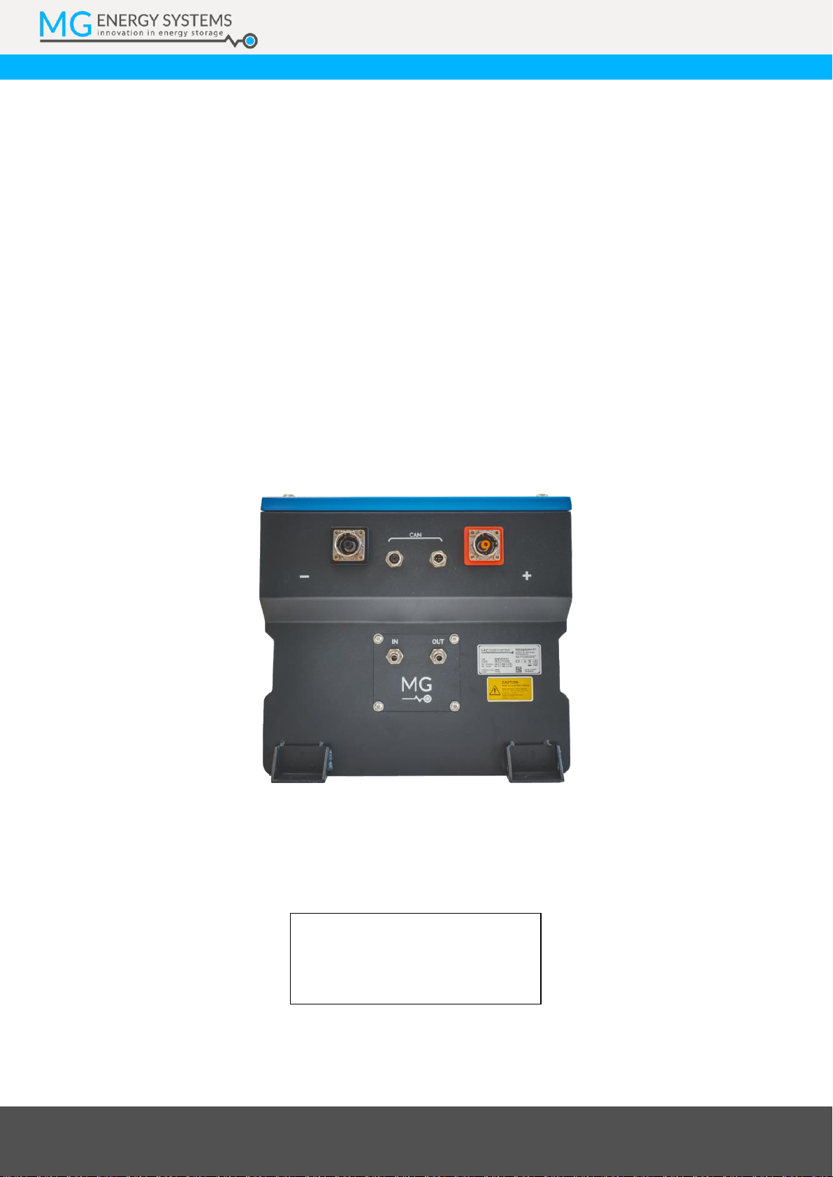
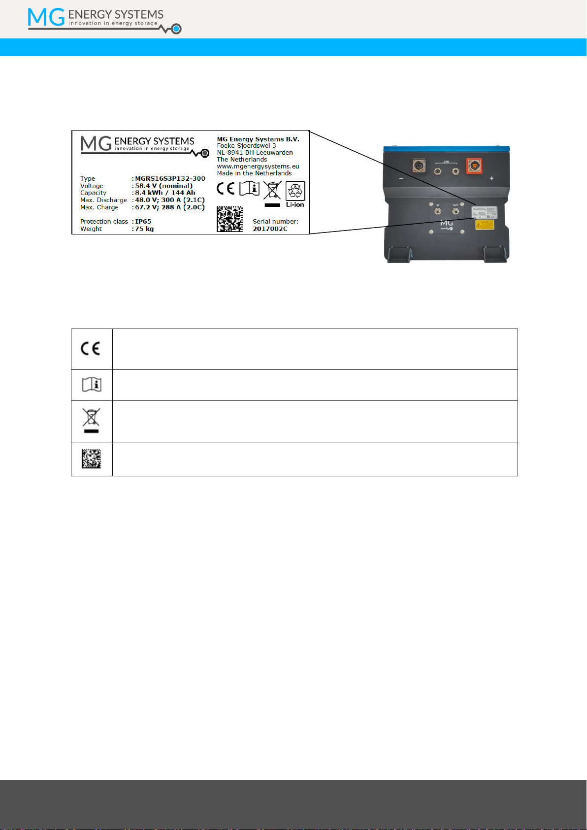
5.2 Identification label
The identification label of the MG RS battery module is located at the front of the enclosure.
Example identification label:
Figure 4 - Example identifications label
The identifications label shown in figure 4 contains written information about the product. The
explanation of the symbols used on the identification label is stated in table 6.
Table 6 - Identification lable logo explaination
Declaration of conformity with health, safety, and environmental protection standards
for products sold within the European Economic Area as per directive 2014/35/EU.
Symbol indication the manual must be red before installation and use of the device.
Device is treated according the Waste Electrical and Electronic Equipment (WEEE)
Directive 2012/19/EU.
GS1 data matrix type barcode containing detailed product information.
MG Energy Systems B.V. | Foeke Sjoerdswei 3 | 8914 BH Leeuwarden | The Netherlands
Innovation in energy storage
6OVERVIEW
This chapter shows an overview of all connection and its functions.
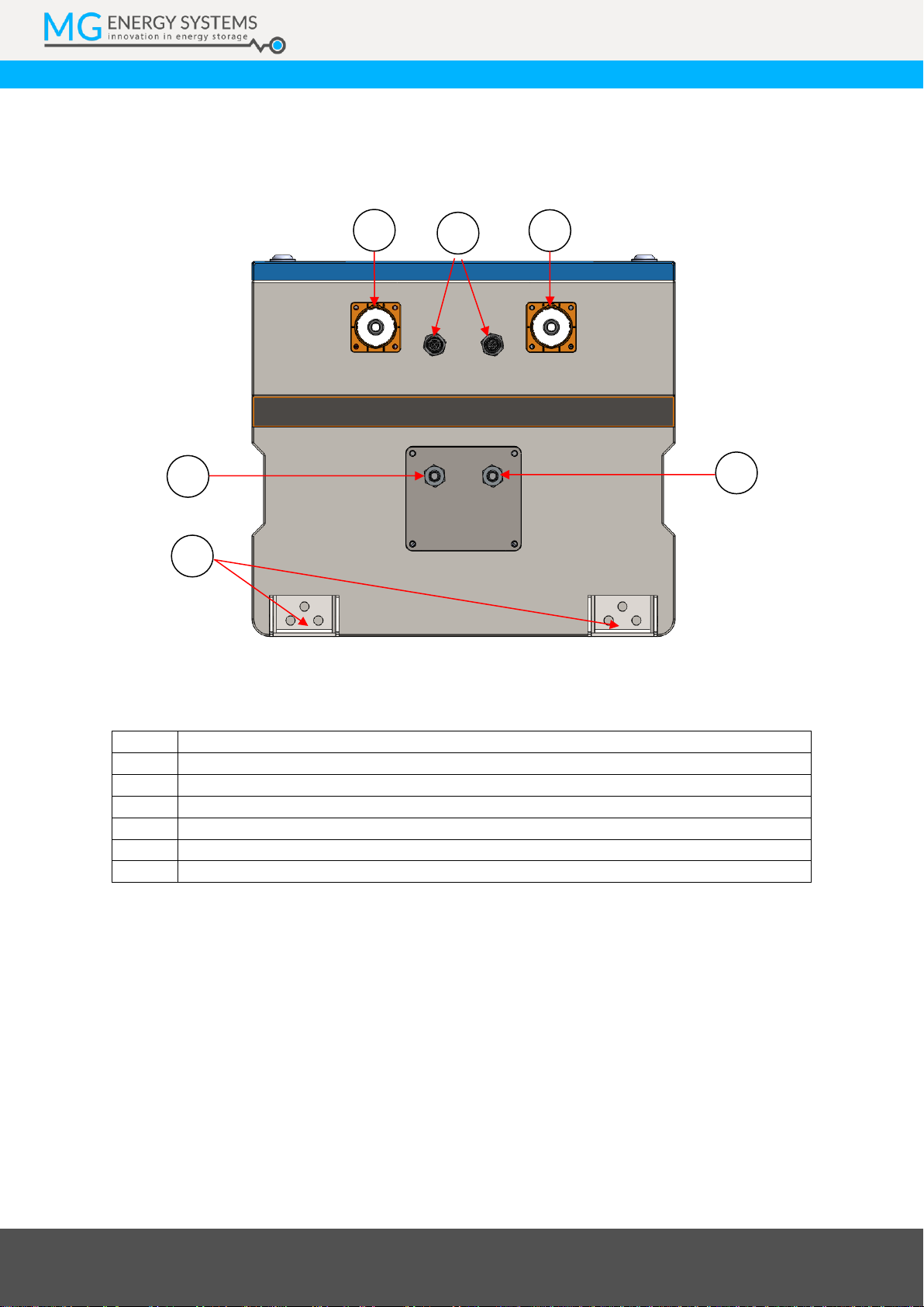
6.1 Front view
Figure 5 - RS module overview front
Table 7 - Battery module front view legend
Item
Description
A
Fluid cooling inlet
B
Fluid cooling outlet
C
Negative power connection
D
Positive power connection
E
CAN-Bus communication
F
Mounting connections and equipotential bonding connection
A
B
C
D
E
F
MG Energy Systems B.V. | Foeke Sjoerdswei 3 | 8914 BH Leeuwarden | The Netherlands
Innovation in energy storage
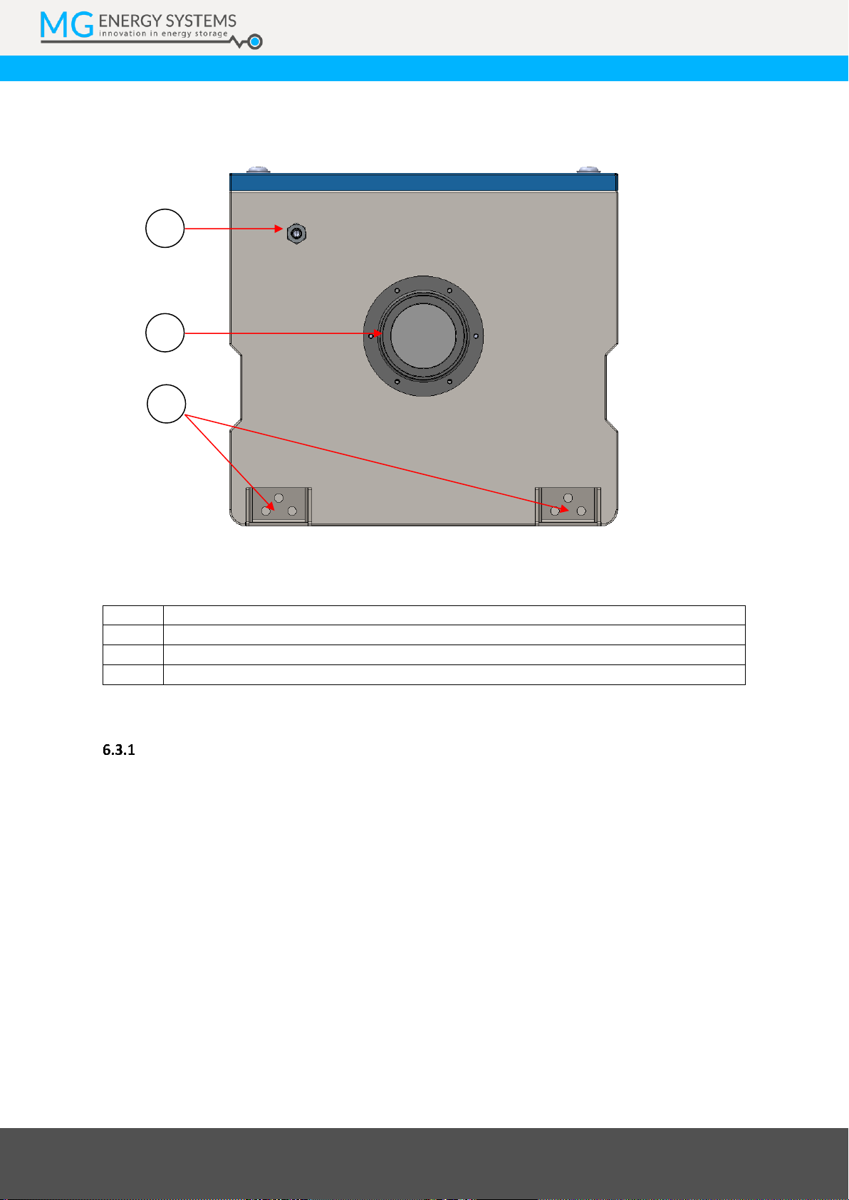
6.2 Rear view
Figure 6 - RS module overview rear
Table 8 –Battery module rear view legend
Item
Description
G
Exhaust connection with pressure relief
H
PPS connection
I
Mounting connections and equipotential bonding connection
6.3 Connections details
CAN-bus connector details
A MG Master BMS communicates with the connected battery modules via CAN-bus. This is a
dedicated CAN-bus where only MG battery modules of the same type or other MG devices may be
connected.
The CAN-Bus connection is used for several functions:
Data communication between battery module(s) and master BMS;
The battery module uses the CAN-Bus V+ voltage to enable the power of the internal BMS;
The CAN-Bus V+ voltage is also used as HVIL voltage source;
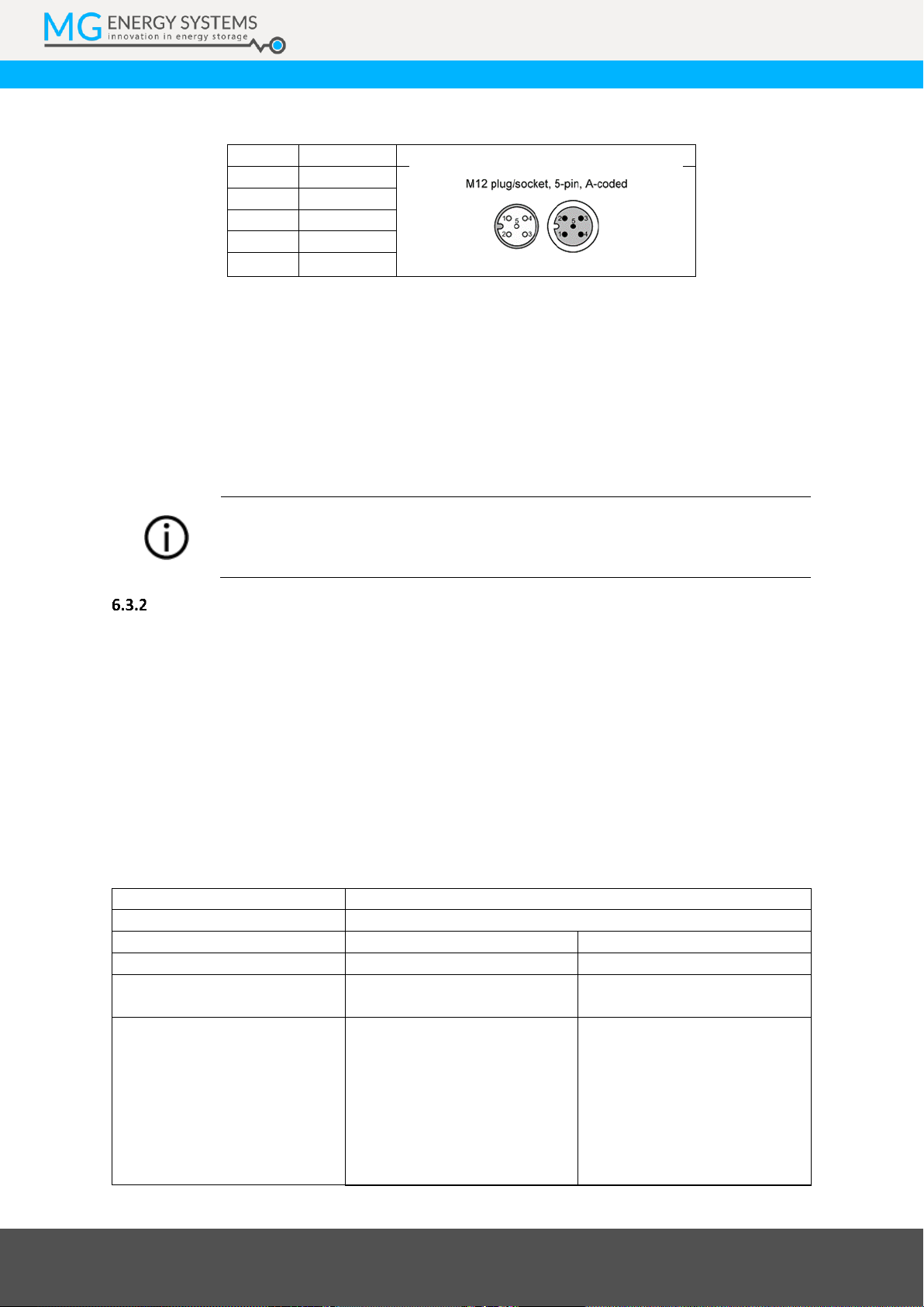
6.3.1.1 Connector details
The connectors used for connecting the battery, auxiliary, and diagnostics CAN-bus are all of the
same type, namely a circular M12 connector with 5 positions and A-coded keying.
H
G
I
MG Energy Systems B.V. | Foeke Sjoerdswei 3 | 8914 BH Leeuwarden | The Netherlands
Innovation in energy storage
Table 9 - Circular M12 connector with 5 positions A-coded details
Pin
Description
Connector view (mating side)
1
Shield
Male Female
2
V+
3
GND
4
CAN-H
5
CAN-L
Cables to be used for the battery system are typically referred to as NMEA 2000 or DeviceNet
compatible cables. The minimum requirements for cables are:
Twisted pair connected to pins 4 and 5 for communication with a minimum wire cross
sectional area of 0.2 mm2(24 AWG).
Pair of conductors connected to pin 2 and 3 for power and HVIL with a minimum wire cross
sectional area of 0.34 mm2(22 AWG).
Cable with braided shielding connected to pin 1.
NOTICE:
Do not use sensor/actor cables. They often don’t have any twisted pairs and are
therefore not suitable for this application.
Power connections
For the RS battery module’s power connections, Amphenol PowerLok™300 Series or Amphenol
PowerLok™500 Series are used. These power connectors can handle a voltage of 1000 VDC and
have an integrated HVIL for safety.
The continuous current of the system is depending on the connected Amphenol PowerLok™ series
and cable cross section.
6.3.2.1 Connector details
Table 10 and table 11 show an overview of the standard connector types in relation with the models
and the maximum current. Contact MG Energy Systems B.V. for cable options and possibilities.
Table 10 - Amphenol PowerLok™500 series
Brand
Amphenol PowerLok™
Series
500 series
Positive terminal (orange)
Negative terminal (black)
Receptacle types
(mounted on MG RS module)
PL00X-501-10-M10
PL00Y-501-10-M10
Plug must be of HVIL type.
Over-moulded cable
assembly:
PL20X-501-120: 350A
PL20X-501-135: 400A
PL20X-501-150: 500A
PL10X-501-120: 350A
PL10X-501-135: 400A
PL10X-501-150: 500A
Over-moulded cable
assembly:
PL20Y-501-120: 350A
PL20Y-501-135: 400A
PL20Y-501-150: 500A
PL20Y-501-120: 350A
PL20Y-501-135: 400A
PL20Y-501-150: 500A
This manual suits for next models
12
Table of contents
Popular Control Unit manuals by other brands


Graco
Graco PD44 Setup & operation

Sungrow
Sungrow EyeM4A quick guide

Lippert Components
Lippert Components OneControl X1 OEM INSTALLATION MANUAL

Riello
Riello RMG 8862 A2 Installation, use and maintenance instructions

Magnescale
Magnescale MG70-PN instruction manual

WinSystems
WinSystems PCM-CFLASH-2 Operation manual


