MG 20VS5-G200 User manual

20VS5-G200
P. 1 / 4
EM-4442 Rev.1
MG CO., LTD. www.mgco.jp
5-2-55 Minamitsumori, Nishinari-ku, Osaka 557-0063 JAPAN
ISOLATION AMPLIFIER
(high-accuracy, input isolation) MODEL
20VS5-G200
INSTRUCTION MANUAL
BEFORE USE ....
Thank you for choosing us. Before use, check the contents of
the package you received as outlined below.
If you have any problems or questions with the product,
please contact our sales office or representatives.
■PACKAGE INCLUDES:
Amplifier ....................................................................... (1)
■MODEL NO.
Confirm that the model number described on the product is
exactly what you ordered.
■INSTRUCTION MANUAL
This manual describes necessary points of caution when
you use this product, including installation, connection and
basic maintenance procedures.
POINTS OF CAUTION
■POWER INPUT RATING & OPERATIONAL RANGE
• Power Supply
Operational voltage range: 15 V DC ±10%
Power consumption: Approx. 7 mA DC (no load)
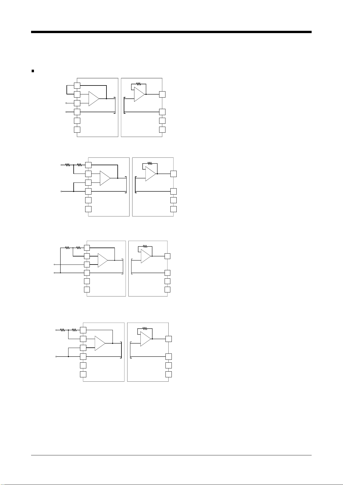
Install the filter for the power supply as indicated below.
■ENVIRONMENT
• Indoor use
• When heavy dust or metal particles are present in the air,
install the unit inside proper housing with sufficient ven-
tilation.
• Do not install the unit where it is subjected to continuous
vibration. Do not apply physical impact to the unit.
• Environmental temperature must be within -10 to +70°C
(14 to 158°F) with relative humidity within 30 to 90% RH
in order to ensure adequate life span and operation.
■WIRING
• Do not install cables (power supply, input and output)
close to noise sources (relay drive cable, high frequency
line, etc.).
• Do not bind these cables together with those in which
noises are present. Do not install them in the same duct.
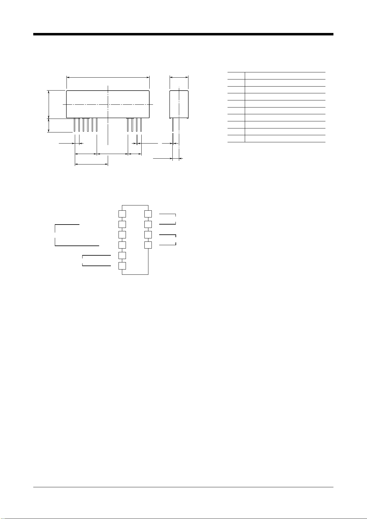
■INSTALLING THE MODULE
When it is installed on the printed wiring board, land diam-
eter ø1.5 and through-hole ø0.9 are recommended.
■AND ....
• The unit is designed to function as soon as power is sup-
plied, however, a warm up for 10 minutes is required for
satisfying complete performance described in the data
sheet.
• With voltage output, do not leave the output terminals
shortcircuited for a long time. The unit is designed to en-
dure it without breakdown, however, it may shorten ap-
propriate life duration.
CHECKING
1) Terminal wiring: Check that wiring is correctly connect-
ed according to the connection diagram.
2) Power input voltage: Check voltage across the pins.
3) Input: Check that the input signal is within 0 – 100% of
the full-scale.
4) Output: Check that the load resistance meets the de-
scribed specifications.
10µF
+
–
COM
POWER
560µH
14
15
+15V
10µF
+
–

20VS5-G200
P. 2 / 4
EM-4442 Rev.1
MG CO., LTD. www.mgco.jp
5-2-55 Minamitsumori, Nishinari-ku, Osaka 557-0063 JAPAN
TERMINAL CONNECTIONS
■EXTERNAL DIMENSIONS mm (inch)
■TERMINAL ASSIGNMENTS
+
–
+
–
OUTPUT
2
1
6
14
15
5
3
4
17
16
+
–
POWER
Note. The reference voltage source is common to the COM (–), terminal 4.
*To be used in the printing wiring board on which the unit is mounted.
REFERENCE VOLTAGE SOURCE*
COM (–)
INPUT NON-INVERTING INPUT
INVERTING INPUT
FEEDBACK
PIN ASSIGNMENT
6
5
4
3
2
1
REFERENCE VOLTAGE SOURCE (–)
REFERENCE VOLTAGE SOURCE (+)
COM (–)
NON-INVERTING INPUT
17
16
15
14
OUTPUT (+)
OUTPUT (–)
POWER SUPPLY (–)
POWER SUPPLY (+)
INVERTING INPUT
FEEDBACK
161417
12.7 (.5) 20.32 (.8) 7.62
(.3)
0.5 (.02)
2.54 (.1) 0.25
(.01)
20.32 (.8)
MAX. 47.5 (1.87) 10.7 (.42)
MAX. 16 (0.63)7.75
(.31)
2.55 (.1)

20VS5-G200
P. 3 / 4
EM-4442 Rev.1
MG CO., LTD. www.mgco.jp
5-2-55 Minamitsumori, Nishinari-ku, Osaka 557-0063 JAPAN
APPLICATION EXAMPLES
The primary amplifier in this unit is high accurate. Installing external resistors to the inverting input (pin 2) and the feed-
back (pin 1), this unit can be used as a non-inverting or inverting amplifier.
The series resistance of the amplifier, R2+ R2must be less than 200kΩ.
The output is proportional to the input.
The gain is 0.98.
E.g. ±4.9 V DC for ±5 V DC input.
The output is inverted to the input. The
gain is -1.
E.g. +5 V DC for -5 V DC input and -5 V
DC for +5 V DC input.
+
–
+
R2R1
–
+
–
Non-inverting amplifier circuit G = 1 + R1/ R2
OUTPUT VO
■Non-inverting amplifier circuit: Example of G = 1 + R1/ R2
INPUT VIN
+
–
–
+
REFERENCE
VOLTAGE SOURCE
1
2
4
3
5
6
+
–
POWER 15V DC
17
16
14
15
For a non-inverting amplification the out-
put is following.
VO= (1 + R2/ R2) × VIN
When R2= 10 kΩ, R2= 10 kΩ, then the
output is following. The gain is 2.
VO= 2 ×VIN
+
–
+
R2R1
–
+
–
Inverting amplifier circuit G = -R1/ R2
OUTPUT VO
■Inverting amplifier circuit: Example of G = -R1/ R2(output inverted to the input)
INPUT VIN +
–
–
+
REFERENCE
VOLTAGE SOURCE
1
2
4
3
5
6
+
–
POWER 15V DC
17
16
14
15
For an inverting amplification the output
is following.
VO = -(R2/ R2) × VIN
When R2= 20 kΩ, R2= 10 kΩ, then the
output is following. The gain is -2.
VO= -(20 kΩ / 10 kΩ) × VIN = -2 × VIN
+
–
+
–
+
–
1
2
Non-inverting circuit G = 0.98
OUTPUT ±4.9V DC
–
+
REFERENCE
VOLTAGE SOURCE
■Non-inverting amplifier circuit: Basic example of G = 0.98
INPUT ±5V DC
+
–
4
3
5
6
17
16
+
–
POWER 15V DC
14
15
+
‒
+
R2R1
‒
+
‒
Inverting circuit G = -1
OUTPUT ±5V DC
■Inverting amplifier circuit: Basic example of G = -1 (output inverted to the input) (R1≈R2)
INPUT ±5V DC +
‒
‒
+
REFERENCE
VOLTAGE SOURCE
1
2
4
3
5
6
17
16
+
‒
POWER 15V DC
14
15

20VS5-G200
P. 4 / 4
EM-4442 Rev.1
MG CO., LTD. www.mgco.jp
5-2-55 Minamitsumori, Nishinari-ku, Osaka 557-0063 JAPAN
For a non-inverting amplification
with external adjustments, when
the combined resistance of the
span adjustment and 9 kΩ is 10
kΩ, the gain is (1 + 10 kΩ / R2)
× VIN. With the span adjustment
(2 kΩ), the output is configurable.
The zero is adjustable with a ref-
erence voltage source of ±7 V DC
and the attenuation of 200 Ω and
30 kΩ.
For an inverting amplification
with external adjustments, when
the combined resistance of the
span adjustment and 9 kΩ is 10
kΩ, the gain is -(10 kΩ / R2) ×VIN.
With the span adjustment (2 kΩ),
the output is configurable. The
zero is adjustable with a refer-
ence voltage source of ±7 V DC
and the attenuation of 200 Ω and
30 kΩ.
MAINTENANCE
Regular calibration procedure is explained below:
■CALIBRATION
Warm up the unit for at least 10 minutes. Apply 0%, 25%,
50%, 75% and 100% input signal. Check that the output
signal for the respective input signal remains within accu-
racy described in the data sheet.
+
–
+
–
Non-inverting amplifier circuit zero/span adjustments (input ±2.5V, output ±5V)
OUTPUT ±5V DC
■ Non-inverting amplifier's circuit with external adjustments: Example of G = 2
+
–
–
+REFERENCE
VOLTAGE
SOURCE
9kΩ
10kΩ
50kΩ
(ZERO)
2kΩ
(SPAN)
INPUT ±2.5V DC
10kΩ
30kΩ
200Ω
+
–
1
2
4
3
5
6
+
–
POWER 15V DC
17
16
14
15
+
–
Inverting amplifier circuit zero/span adjustments (input ±5V, output ±5V)
■ Inverting amplifier's circuit with external adjustments: Example of G = -1 (output inverted to the input)
+
–
–
+REFERENCE
VOLTAGE
SOURCE
9kΩ
10kΩ
100kΩ
(ZERO)
2kΩ
(SPAN)
INPUT ±5V DC
10kΩ
30kΩ
200Ω
+
–
+
–
OUTPUT ±5V DC
1
2
4
3
5
6
+
–
POWER 15V DC
17
16
14
15
Other MG Amplifier manuals