MGC QMT-5302NV User manual
LT-6036 Rev 1 Sep 2012 Page 1 of 6
QMT-5302NV
Network Master Firefighters’ Telephone
Installation Instructions
QMT-5302NV Network Master Firefighters’ Telephone
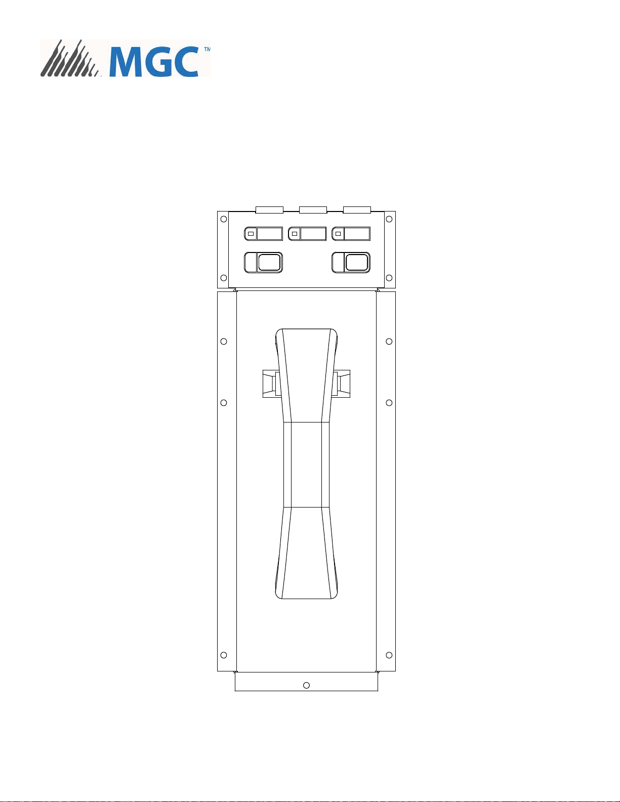
The QMT-5302 Network Master Firefighters’ Telephone fits into the BBX-FXMNS Enclosure. It mounts on the inner
deadfront chassis (part of the BBX-FXMNS door assembly). Connections and terminal wiring is the same as for the
QMT-5302N.
Figure 1: QMT-5302NV Network Master Firefighters’ Telephone
CALL CONTROL
ACTIVE
CALL CONTROL
DESELECT ALL
TROUBLE INCOMING CALL
LT-6036 Rev 1 Sep 2012 Page 2 of 6
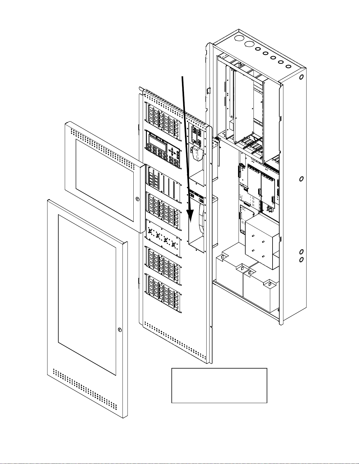
Figure 2: BBX-FXMNS Enclosure Complete View
FRONT DOORS AND INNER
DEADFRONT CHASSIS
BACKBOX
QMT-5302NV Network
Fireghters’ Telephone
Mount the QMT-5302NV onto the
inner deadfront chassis using the
eleven #6 HEX nuts provided.

LT-6036 Rev 1 Sep 2012 Page 3 of 6
QMT-5302NV Network Master Firefighters’ Telephone
The QMT-5302NV Network Master Firefighters' Telephone is used in conjunction with the Network Fire Alarm system.
Slide-in labels (NP-7048) are supplied with the Master Telephone. Place labels as shown in Figure 3. The QAZT-
5302/DS Telephone Selector panels are used for selecting telephone zones (up to 24 zones per selector panel) and
include blank labels for labelling the telephone zones.
Figure 3: QMT-5302NV Network Firefighters’ Telephone Label Placement
CALL CONTROL
ACTIVE
CALL CONTROL
DESELECT ALL
TROUBLE INCOMING CALL

LT-6036 Rev 1 Sep 2012 Page 4 of 6
QMT-5302NV Network Master Firefighters’ Telephone Wiring
The connection required on the QMT-5302NV Network Master Firefighters’ Telephone board is the ribbon cable from
the previous display module to P1 or IN connector on the bottom center of the board and the OUT connection goes to
the IN connector of the next display board.
The master telephone positive and negative terminals (located on the back of QMT-5302NV) connect to the TNC-5000
Zone 1 positive and negative terminals with twisted pair wires. Refer to Figure 4 below for connector and terminal
block locations of the QMT-5302NV.
Figure 4: QMT-5302NV Cable Connection and Terminal Wiring
-+
Connection from previous display
Connection to
Telephone
Selector Panel P1
or next display
IN
OUT
To TNC-5000 Telephone Zone 1
positive and negative terminals
(twisted pair wire)
P1
P2
Terminal connection located on the back of the
QMT-5302NV Network Master Firefighters’Telephone
LT-6036 Rev 1 Sep 2012 Page 5 of 6
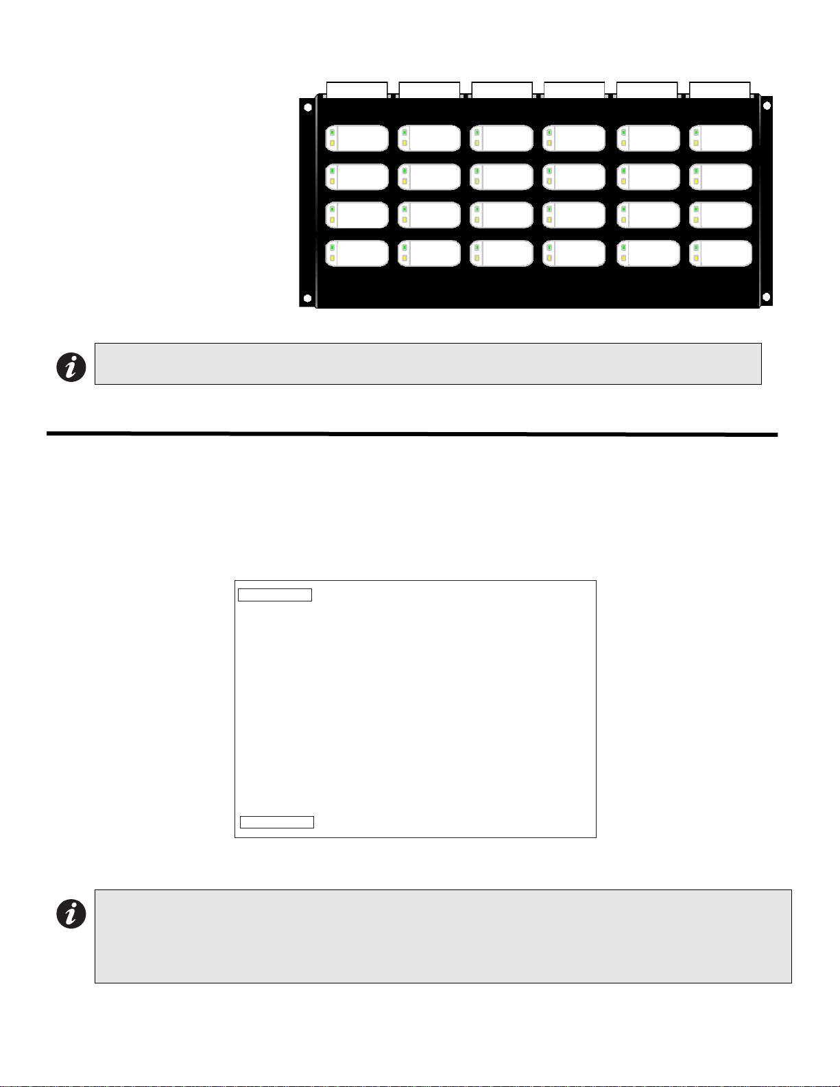
Figure 5: QAZT-5302/DS Network Firefighters' Telephone Selector Panel
Each QAZT-5302/DS annunciates
and controls up to 24 telephone
zones. There is one button and two
LEDs per zone. The lower amber
LED indicates zone trouble. The
upper green LED indicates whether
that zone is selected for telephone
communication.
Press the button to turn the
selection for telephone
communication for that zone ON
and OFF.
QAZT-5302/DS Network Firefighters’ Telephone Selector Panel
Connect the first QAZT-5302/DS Network Firefighters’ Telephone Selector panel to the master telephone by
connecting P1 cable into P2 on the QMT-5302NV Master Telephone. P2 of the QAZT-5302/DS is connected to P1 of
the next display panel (up to six total).
Figure 6: QAZT-5302/DS Telephone Selector Board
Note: Use configurator to set up the QAZT-5302/DS Telephone Zone Selector Panels.
Note: All panels such as QMP-5101NV Network Master Paging Control Module, the QMT-5302NV Network Master
Firefighters’ Telephone Control Module, the IPS-2424/DS display module and the paging or telephone
selector panel QAZT-5302/DS are daisy chained together starting from the Networ display module, DSPL-
420, DSPL-2440, RAXN-LCD or RAXN-LCDG. Total number of boards allowed in the daisy chain
connection is 6 (12 frames).
Telephone
#1
Telephone
#2
Telephone
#3
Telephone
#4
Telephone
#5
Telephone
#6
Telephone
#7
Telephone
#8
Telephone
#9
Telephone
#10
Telephone
#11
Telephone
#12
Telephone
#13
Telephone
#14
Telephone
#15
Telephone
#16
Telephone
#17
Telephone
#18
Telephone
#19
Telephone
#20
Telephone
#21
Telephone
#22
Telephone
#23
Telephone
#24
P2
P1
CONNECTION TO NEXT DISPLAY PANEL
P1 CONNECTS TO P2 OF THE QMT-5302N NETWORK MASTER TELEPHONE CONTROL MODULE
QAZT-5302 ADDRESSABLE
TELEPHONE SELECTOR PANEL

LT-6036 Rev 1 Sep 2012 Page 6 of 6
Telephone Operation
1. When any telephone zone rings (the local buzzer sounds intermittently, and the green zone LED and Incoming
Call LED flash) press that zone's button (on the selector panel QAZT-5302/DS) once to answer. Once any one
zone has been answered, calls from any other zone will cause that zone's green LED and the Incoming Call LED
at the master telephone to flash and the buzzer will sound.
2. Press the answered zone's button once again to hang up. (Note that the telephone zone will hang up
automatically if all handsets on the zone are placed back on the hook.)
3. Press DESELECT ALL to disconnect all connected telephones zones.
QMT-5302NV Master Telephone LEDs
Trouble LED
This LED will flash amber if there is any zone or other trouble in the firefighters' telephone system.
Incoming Call LED
This LED will flash green if any telephone zone has a handset off-hook and unanswered. It will illuminate steady green
if all telephone zones with off-hook handsets have been answered.
Call Control Active LED
This LED will illuminate when there is a connection between the designated Master Telephone (at the CACF) and the
present QMT-5302NV telephone.
QMT-5302NV Master Telephone Pushbutton Controls
Call Control
Pressing this pushbutton will connect this telephone with the designated Master Telephone (possibly at the Central
Alarm and Control Facility (CACF).
Deselect All
Pressing this pushbutton will disconnect all selected telephone zones.
QAZT-5302/DS Network Firefighters’ Telephone Selector Panel LEDs
Telephone Zone Green LED
This LED will flash green if there is any handset off-hook on that zone, and the zone has not been answered by
pressing the zone's button. Once answered, the LED will be steady green.
Telephone Zone Amber LED
This LED will flash amber to indicate trouble on open-circuit zone faults (e.g. missing end-of-line resistor or wire
breaks) or short-circuit zone faults.
QAZT-5302/DS Network Firefighters’ Telephone Selector Panel Pushbutton Controls
Telephone Selection Pushbutton
Pressing the telephone selector pushbutton will select the associated telephone to be connected to the Master
Telephone. Pressing this button a second time will hang up.


CANADA - Main Office
25 Interchange Way
Vaughan, ON L4K 5W3
Tel: (888) 660-4655
(905) 660-4655
Fax: (905) 660-4113
© MGC 2012
Printed in Canada
Subject to change without prior notice
www.mircomgroup.com
U.S.A
4575 Witmer Industrial Estates
Niagara Falls, NY 14305
Tel: (888) 660-4655
(905) 660-4655
Fax: (905) 660-4113
TECHNICAL SUPPORT
North America
Tel: (888) Mircom5
(888) 647-2665
International
Tel: (905) 647-2665
Table of contents


