MGI Navigator NVR750c Manual

NAVIGATOR NVR750c
MAINTENANCE/SERVICE MANUAL
INSTRUCTION MANUAL

2
INDEX
MAINTENANCE / SERVICE MANUAL
1. Foreword
2. Important
3. Warranty Registration
4. Warranty Service Problem
5. Warranty Policy
6. Warranty Exclusions
7. Parts Installed During Warranty
8. Preventative Maintenance Program
9. Cleaning Your Motorised Buggy
10. Rear Wheel Axles
11. Upper & Lower Bag Straps
12. Correcting the Alignment of Your Buggy
13. MGI Service Schedule:
14. Service Record:
INSTRUCTION MANUAL
1. Most Important points to read prior to using your buggy
2. Charging and care of the Battery
3. Fitting the Battery
4. Battery Lead Fuse
5. Fail Safe Connection
6. Attaching / Removing Wheels
7. Understanding the Electronics of the NVR750c
8. Folding / Unfolding the Buggy
9. Fitting your Golf Bag
10. Positioning the Seat
11. Assembling the Umbrella Holder
12. Sand Bucket Loop
13. Engaging the 4th Wheel
14. The Front Wheel and Suspension System
15. Top Handle Control Box Features
16. Transmitter Features
17. The Navigation System – How it works
18. Cart Tracking
19. Useful Hints in Operating the Navigator NVR750c
20. Understanding your Buggy and Suggestions for Dealing with unusual Situations
21. Frequently Asked Questions

3
MAINTENANCE SERVICE MANUAL
1. Foreword
Congratulations on the purchase of your Navigator NVR750c Buggy.
To ensure continued efficiency of your MGI motorised buggy, regular maintenance at periodic
intervals is essential. For guidance, this booklet contains a schedule applicable to the
maintenance required at the appropriate times and a service record.
2. Important
If operating in conditions such as those mentioned below, speed controls, clutches, frame
alignment, adjustment, tightening and axle alignment should be serviced at more frequent
intervals than specified in this booklet:
a. playing more than twice a week
b. damp or wet conditions
c. rough, dusty or sandy conditions
d. hilly conditions
3. Warranty Registration
Warranty registration can be made either on-line at www.mgikaddy.com or using the warranty
registration card supplied with your motorised buggy. It must be completed and returned to MGI
within 14 days of purchase.
4. Warranty Service Problem
Purchase date of the motorised buggy must be given before warranty is accepted for processing.
In the event of a need for warranty service, either refer to the list of authorised service centres or
call MGI on 1300 644 523
5. Warranty Policy
MGI NVR750c - For a period of 12 months in respect of the electronics, wheels, clutches, drive
dogs, axles, battery and charger and 24 months in respect of the frame, motor and gearbox, MGI
or an authorised service centre or person will repair or replace free of charge any parts found to
be defective in materials or workmanship under normal use provided that:
1. The NVR750c has been properly used, maintained and regularly serviced
2. The replacement or repair is performed by an authorized MGI service centre or the owner
with MGI approval.

4
6. Warranty Exclusions - the following events void warranty:
a. Any defect caused by misuse, negligence, accident or failure to carry out proper
maintenance procedures.
b. Any alteration performed by non authorised people or companies.
c. Fitting of parts or accessories not recommended by MGI.
d. Any damage caused by continued operation of the motorised buggy after it is known to be
defective.
e. Damaged seat support bracket on buggy chassis
All implied warranties [save those preserved by statute] are excluded. Liability for consequential
damages under any and all warranties are excluded to the extent exclusion is permitted by law.
7. Parts Installed During Warranty
Warranty coverage for components installed during a motorised buggy’s warranty period shall
consist of the duration of the buggy’s warranty period, provided the warranty installation is
performed by MGI, an authorised service centre or the buggy owner on approval.
8. Preventative Maintenance Program
To properly provide for the continued operation of your motorised buggy, MGI has introduced its
Preventative Maintenance Program [PMP]. The PMP consists of work to be carried out by both
the owner and authorised service centres. To properly maintain the warranty of your MGI
motorised buggy, it is essential that this work is carried out. If the work carried out by the
authorised service centre is to replace parts that are part of the maintenance schedule, the owner
will be charged for the parts and labour. If the work to be carried out is part of warranty, MGI will
bear the cost.
9. Cleaning Your Motorised Buggy [See Maintenance Schedule]
For years of good operation, your buggy requires care and attention. Keep your buggy clean by
using a cloth with warm water and a mild detergent. Do not hose down your buggy under any
circumstance, as your buggy has electronic components. Ensure that the seat stem bracket and
sand bucket loop bracket plastic inserts are cleaned to remove dirt and sand.
In addition remove and clean the 4th wheel tube [see part 14 page 15].

5
10. Rear Wheel Axles [See Maintenance Schedule]
The rear wheel stub axles need to be lubricated regularly. Remove the rear wheels by depressing
the spring clip and at the same time pull off the wheel. Apply Petroleum Jelly or light grease to
the stub axles. Use a very small amount as the grease can attract sand. If you play in sandy
conditions you should clean your axle and regrease fortnightly.
To refit the rear wheels you will need to align the wheel’s four sided slot to its equivalent on the
buggy to ensure the wheels are properly engaged. Ensure that the wheels are put on the correct
side ‘L’ and ‘R’ [see part 6, page 12].
11. Upper & Lower Bag Straps [See Maintenance Schedule]
The upper and lower bag straps should be replaced as per the Service Schedule on page 5. The
upper bag strap can be replaced by:
1. Removing the left and right hand straps form the upper bag support.
2. Undo and remove the screws holding the strap in position on the bag support
3. Remove and replace both bag straps.
4. Insert bag strap securing screws.
The lower bag strap can be replaced by unclipping it from the bag support and installing the new
bag strap.
12. Correcting the Alignment of your Motorised Buggy [See Maintenance Schedule]
RIGHT LEFT
If during use, you find that the buggy veers to the right or left,
please follow the instructions below to correct this problem:
1. If the buggy veers to the left, face the front wheel of
the buggy and use the Allen key provided to screw the
right bolt clockwise or the left bolt anti-clockwise.
2. If the buggy veers to the right, face the front wheel of
the buggy and use the Allen key provided to screw the
left bolt clockwise or the right bolt anti clockwise.
Test run the buggy and repeat the process until the buggy
runs straight.
Undo screw
s

6
13. MGI Service Schedule [NVR750c]:
It is the owner’s responsibility to ensure that all periodical checks, necessary adjustments and
services are carried out. If in doubt please contact the MGI service centre on 1300 644 523. Any
work performed on your buggy should be recorded on your service record (see page 9)
regardless of the work.
NVR750c Monthly Six
Monthly Yearly Three
Yearly
Wipe down the buggy with warm cloth after each use –
see page 4 point 9 BO
Clean 4th wheel – see page 16, point 14 BO
Lubricate rear wheel stub axles – see page 5 point 10 BO
Check and tighten all nuts and bolts BO/SC
Check grub screws on bearing collars on axle bearings -
tighten as required BO/SC
Check and tighten handle pivots BO/SC
Check alignment of buggy - ensure that it runs straight –
see page 5 point 13 BO/SC
Replace handle grips BO/SC
Replace rear wheel drive dogs BO/SC
Replace rear wheel spring latches BO/SC
Replace rear wheel drive hubs BO/SC
Replace seat bracket & sand bucket loop plastic inserts BO/SC
Replace fused battery leads BO/SC
Replace top box label BO/SC
Replace rear and front wheels – see page 10 point 5 BO
Replace 4th Wheel Assembly – see page 16 point 14 BO
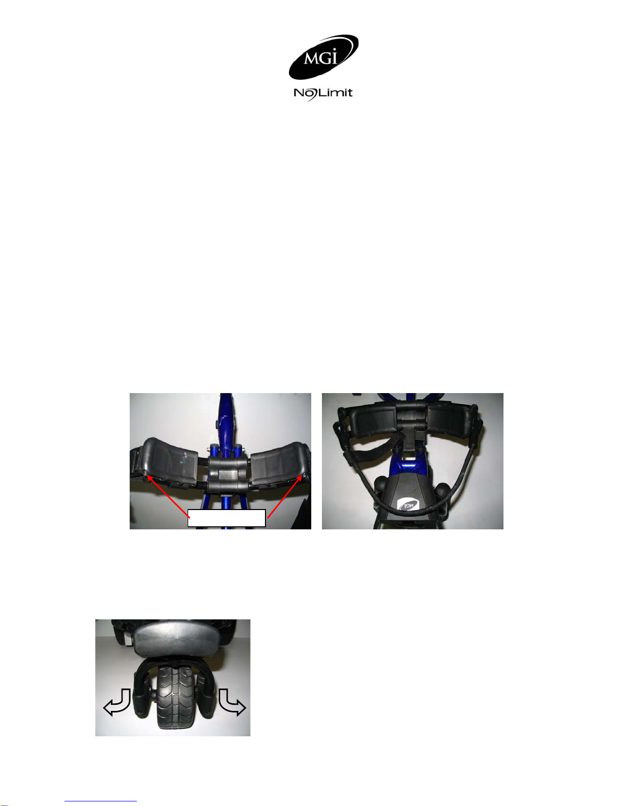
Replace Upper & Lower Bag Straps – see page 5 point 12 BO
BO = Buggy owner can carry out this work
SC = Charged work to be carried by approved service centre
BO/SC = The six monthly service can be completed by either an authorised service centre or the
owner of the buggy. The tools to tighten all nuts and bolts are provided with your maintenance /
service and instruction manual. As part of MGI’s Preventative Maintenance Program, if the six
monthly services are carried out by an authorised service centre, you will be charged for that
service. Each yearly service should also include the six monthly service.
It is important for your warranty and the life of your buggy that the service record be observed and
maintained. Monthly cleaning and lubrication need not be recorded on the service record.

7
14. Service Record For NVR750c
SIX MONTH INSPECTION DATE: SERVICED BY:
.
INVOICE NO: SIGNATURE:
ONE YEAR INSPECTION DATE: SERVICED BY:
.
INVOICE NO: SIGNATURE:
1½ YEAR INSPECTION DATE: SERVICED BY:
.
INVOICE NO: SIGNATURE:
TWO YEAR INSPECTION DATE: SERVICED BY:
.
INVOICE NO: SIGNATURE:
2½ YEAR INSPECTION DATE: SERVICED BY:
.
INVOICE NO: SIGNATURE:
THREE YEAR INSPECTION DATE: SERVICED BY:
.
INVOICE NO: SIGNATURE:
3½ YEAR INSPECTION DATE: SERVICED BY:
.
INVOICE NO: SIGNATURE:
FOUR YEAR INSPECTION DATE: SERVICED BY:
.
INVOICE NO: SIGNATURE:
4½ YEAR INSPECTION DATE: SERVICED BY:
.
INVOICE NO: SIGNATURE:
FIVE YEAR INSPECTION DATE: SERVICED BY:
.
INVOICE NO: SIGNATURE:
5½ YEAR INSPECTION DATE: SERVICED BY:
.
INVOICE NO: SIGNATURE:
SIX YEAR INSPECTION DATE: SERVICED BY:
.
INVOICE NO: SIGNATURE:
ADDITIONAL SERVICE DATE: SERVICED BY:
.
INVOICE NO: SIGNATURE:
ADDITIONAL SERVICE DATE: SERVICED BY:
.
INVOICE NO: SIGNATURE:
ADDITIONAL SERVICE DATE: SERVICED BY:
.
INVOICE NO: SIGNATURE:
ADDITIONAL SERVICE DATE: SERVICED BY:
.
INVOICE NO: SIGNATURE:
Additional Service – this is to record any servicing outside the normal schedule.

8
INSTRUCTION MANUAL
1. Most Important points to read prior to using your buggy:
a. Charging and care of the battery [see below]
b. Assemble the buggy placing the rear wheels on their correct side [see page 10]
c. Programme your Navigator for the chosen handle height [see page 11]
2. Charging and care of the battery
a. Prior to the first and after every use charge the Battery. The battery and charger
comes with an easy connection system. Red to Red and Black to Black.
Important: - The battery must be charged at least over night before its first use.
b. Your battery is designed for 18 holes only. If you play more than 18 holes before
recharging, the battery’s life could be compromised.
c. Always recharge the battery as soon as possible after use, no matter how short the
period of use. Your battery will charge best, lying flat, in a warm and air flowing
location.
Note: In winter, it is best charged off any concrete floor and preferably in a warm
location within the house.
d. During play, minimise the drain on the battery by avoiding taking your buggy into the
rough whenever possible.
e. Avoid as much as possible using the buggy to pull you up the hills.
f. In between use, always leave the charger connected to the battery with power on.
g. If you are not playing golf for sometime, you may disconnect the battery once it is
charged. The battery will need recharging at least every 3 months and must be
recharged prior to use. The battery should be stored in a dry and warm environment.
h. The battery is a sealed battery. If you are intending to take your buggy and battery on
air travel, we advise that you make contact with your airline prior to travel.
i. Be very careful not to drop your battery. The battery casing is easily cracked and the
battery’s subsequent life will be severely compromised.

9
3. Fitting the battery
Once charged, the battery can be fitted to the buggy. The battery comes with a battery cover,
carry handle and battery leads.
a. Place your battery in the tray with the leads facing to the front of the buggy.
b. The battery tray has a battery securing strap.
c. The securing strap is to be used at all times as it protects your battery against damage
from falling out.
d. The battery lead can now be connected to the battery tray. Connect red to red and
black to black.
4. Battery Lead Fuse
Your NVR750c has a 40 amp fuse connected to the battery lead. The 40 amp fuse helps protect
the buggy’s control board against a power surge.
An extra fuse is supplied with your buggy.
In the unlikelihood of your buggy stopping, the reason could be the fuse has blown. Check and
replace if necessary.
The replacement of the fuse will allow you to continue using your buggy. If the fuse blows, contact
your service centre.
5. Fail Safe Connection:
Your buggy has been equipped with fail safe battery connection. Your buggy will only start once
you increase the speed control.

10
6. Attaching / Removing Wheels
If your buggy comes with the wheels off, they should be placed in position prior to unfolding. To
put the wheels on you will need to align the four slots on the inside of the wheel with the same
four on the drive dog on the axle. To engage the rear wheel, depress the quick release catch until
the wheel is in place.
NVR750c Buggy
Your NVR750c buggy uses a gear system, whereby the two rear drive wheels do not free wheel.
The motor needs to be running for the buggy to move. Drive will only occur when the speed
control is turned on.
If for some reason your buggy stops operating during your golf round, your buggy can free wheel.
Simply depress the quick release tag and at the same time move the wheel outwards about
10mm from its current position. Release the tag and allow the wheel to click into its outer
position. By doing this, you have disconnected the wheels from the drive and they can rotate
freely.
Align the four slots on the wheel with
those on the drive dog teeth. Depress the quick release catch,
whilst putting wheel in position on
the axle

11
7. Understanding the Electronics of the NVR750c
Your new Navigator NVR750c uses a highly sophisticated and patented electronic gyroscope as
the navigation system to steer the buggy when in ‘Nav On’ mode. The gyroscope is tilt
compensated to enable true steering over a wide range of grades, which you could expect to
encounter on the average golf course.
Your new NVR750c with electronic gyroscope motor controller will allow the navigation system to
operate at the desired handle height independent of any external conditions.
Your NVR750c employs auto range detection, so the buggy will not go out of range of the remote
control. A battery saving feature has also been added to the operation of your remote control. If
some reason you do not touch the remote control for two minutes whilst your buggy is within
range, the buggy will stop. Simply press a command on the remote and the buggy will resume
whatever task you seek of it.
See Point 17 for understanding ‘Nav On’ and ‘Nav Off’.

12
8. Folding/unfolding your buggy
Practice unfolding and folding the buggy using the steps below. This means when you go to play
golf you will be somewhat familiar with this task.
1. Press the button on the lower folding mechanism and fold the lower handle
2. Press the button on the upper folding mechanism and fold the upper handle
3. Collapse the handle until both folding mechanisms lock into place
4. Bend your knees and lift the buggy using the front lifting handle and rear lifting bar
Step 1 Step 2 Step 3
Step 4
The following order of steps is suggested when folding your buggy down:
a. Seat and stem off first
b. Golf bag off second
c. Battery off and directly into the boot of the car. This will save double handling
d. Sand bucket and loop off
e. Disengage 4th wheel after having removed and wiped it down [see page 15]
f. Remove antenna
g. Fold down buggy and place into the boot of the car

13
9. Fitting your Golf Bag
a. Separate the clip located on the top bag support.
b. Expand the strap to be enough to fit around the golf bag.
c. Place your golf bag on the buggy.
d. Clip the top bag support strap in place.
e. Pull the top bag support strap tight.
f. The bottom strap should not be removed from its position and can be pulled over the
bag by holding the webbed section of the strap and pulling it over the base of the golf
bag.
10. Positioning the Seat
Place the seat stem into its position in the seat stem bracket on the right hand side of the buggy.
MOST IMPORTANT: DEPRESS THE SEAT WITH YOUR HAND BEFORE SITTING. DO NOT
USE THE SEAT ON UNEVEN SURFACES.
Please note MGI does not warrant any seat support brackets that are damaged or bent.

14
11. Assembling the Umbrella Holder
Your buggy comes with an umbrella holder. The umbrella holder needs to be bolted into position.
Simply follow the pictures above. When not in use the umbrella holder can be turned to its side.
If you take your buggy home in your car, you may need to do that prior to folding the buggy down.
Your umbrella holder can be adjusted both to the side and backwards and forwards.
The umbrella is secured inside the umbrella holder by tightening the plastic bolt located near the
top of the holder.
DO NOT LEAVE YOUR UMBRELLA UP IN THE UMBRELLA HOLDER IN WINDY
CONDITIONS.
If the wind catches the umbrella, it could cause your buggy to tip over and cause damage, which
will not be covered by warranty.
12. Sand Bucket Loop
If your buggy comes with a sand bucket loop, place this in position at the rear of the buggy.

15
13. Engaging the 4th Wheel
Important: To avoid damage to your buggy always engage the 4th wheel prior to playing golf,
regardless of the terrain you are playing on.
To engage the 4th wheel, pull on the spring loaded locking pin, begin to slide the 4th wheel back
release the locking pin and continue sliding the 4th wheel back until the locking pin locates itself
into position.
The 4th wheel should be cleaned regularly. Remove the 4th wheel by pulling on the spring loaded
locking pin, slide the 4th wheel all the way out of its housing. The 4th wheel can then be cleaned
with a cloth. Then reinsert the 4th wheel into its housing and pull on the spring loaded locking pin.
14. The Front Wheel and Suspension System
Your buggy has a unique front wheel system. The front wheel can swivel 360 degrees. The
main advantage of this is that your buggy is highly manoeuvrable. You only need to turn the
buggy handle and your buggy will turn. The suspension helps reduce the amount of shock the
buggy will take when going over hills, bumps, ruts, etc…

16
15. Top Handle Control Box Features
a. On/Off – Press the on/off button to turn the buggy on and off
b. Forward Arrow – Press to accelerate the buggy. The longer you depress
the button, the faster the buggy travels
c. Down Arrow – This enables you to decrease the speed and also to operate
the NVR700 in reverse. To reverse your Navigator NVR700, the buggy must first be
stopped.
d. The buggy will move in the backward direction only whilst you keep the down arrow
depressed. If you take your finger off the down arrow the buggy will stop (safety
feature).
e. Buggy Mode – When the buggy is on, the green light means Navigation is on. The
red light means Navigation is off.
f. Battery Status – Battery Light (located on top handle control box) - when the battery
is charged the light is green. If the battery status becomes red, you will only have a
few holes to go and it will stop.
g. Programming - If you need to change the operation of the buggy using programming
features, the light will change to indicate that programming is happening.
Please note: When you touch any of the buttons on the top handle control box, the buggy senses
that you want to take personal control over it and will turn the Navigation system off.

17
16. Transmitter Features
a. Forward Arrow - Press to accelerate the buggy. The longer you depress the
button, the faster the buggy travels. Please note: If you wish to regain the speed you
were travelling at prior to the last stop, simply press the forward button twice in
succession. The buggy will accelerate to the last speed setting. This feature works
only when you press the stop button to stop the buggy rather than pressing the down
arrow.
b. Down Arrow - Decreases the speed and provides for reverse. If you are
moving forward, the down arrow can be used to decrease speed, the longer the
pressure, the slower the speed until it stops.
To operate the Reverse mode you must stop the buggy first. Press the down arrow
and the buggy will reverse. To increase the reverse speed, depress the down arrow
until the desired speed is obtained. To stop the buggy whilst in reverse and using the
transmitter press the Stop button.
c. Left and Right Arrows - Press the appropriate turn command and
keep pressed until the degree of turn achieved. Momentary pressure will make a small
adjustment to the direction, whilst prolonged will increase the amount of turn.
d. Soft Braking - the Navigator NVR750c is equipped with electronic soft braking. This
means when you apply a left or right turn for less than a second, braking will be soft.
This is most useful when you are using your buggy to make small or part turns. If you
press either turn button for more than one second, your buggy will sense you are
wanting a strong turn. At this point full braking is applied.
e. Indicator Light - [in top right corner of transmitter] each time you press a command
using the remote, the light in the top right corner of the transmitter will display a green
light or red light. The green light indicates the Navigation system is on and the red
light indicates the Navigation system is off.

18
f. Transmitter range and Heart Beat: The range of the NVR750c is up to 200 metres
[220 yards]. Your NVR750c also has a heart beat between the transmitter and
receiver. This means that they stay on contact with each other at all times. If for some
reason the buggy was to go out of range of the transmitter your NVR750c will stop
automatically.
17. The Navigation System – How it works.
a. Navigation on [Nav On] - by pressing “Nav On”, the Navigation system is turned on.
The indicator light on the top right hand side of the remote will illuminate green each
time you use a command whilst Navigation is on.
The Navigation system when turned on will ensure the buggy will maintain its direction
regardless of the terrain. The buggy will automatically brake or accelerate either wheel
to maintain its direction.
Useful hint: On a steep incline, the gradient may force the buggy off line. You do not
need to adjust the buggy. The buggy will works its way back on course. In addition, if
the buggy hits a tuft of grass or other object, the buggy will momentarily be forced off
course. Do not be concerned. The buggy knows where to go and will get back on
track quickly.
b. Navigation off [Nav Off] - by pressing “Nav Off”, the Navigation system is turned off.
The indicator light on the top right hand side of the remote will illuminate red each time
you use a command whilst Navigation is off.
Important: When you use the controls on the buggy’s handlebar, the Navigation
system turns off automatically. This will enable you to manoeuvre the buggy. The
mode light on the handlebar will turn red when Navigation turns off.
When you change from using the handlebar controls back to the remote, the buggy
remembers if the remote was in the mode of “Navigation On” or “Navigation Off”. If
the last command on the remote was with Navigation on, the first command using the
remote will also be Navigation on. If that is not what you want, simply press “Nav off
“and the Navigation system will turn off.
When your buggy is turned on, the remote control can be used in the same way as the
controls on the handlebar.

19
18. Cart Tracking
Your Navigator is designed to track straight on level ground in the “Nav Off” mode. The twin
motors are synchronized with your buggy at production. If for some reason (for example, your
golf bag is not evenly weighted) your buggy does not track straight, adopt the following procedure
to get the buggy to do that.
Firstly complete steps 1 to 4 to cancel the existing program using the electronics top box.
Then, complete steps 1 through to only 3 using the top box and then follow up with steps 5 to 8
using the transmitter.
Top Handle Control Box
Transmitter
Step 1
Turn Cart Off – Press “ON
/ OFF” button.
Step 2
Press and hold “PROG”
button for 5 seconds – red
light will flash.
Step 3
Press “reverse arrow” –
“PROG” light will now flash
green.
Step 4
Press the “STOP” button
on the top box. Existing
speed compensation /
correction has now been
removed.
Using the transmitter
Step 5
Press “forward arrow”.
The cart will now move
forward. Watch how
straight the buggy goes.
Step 6
If the cart moves to the left
it means that the R/H
motor is running quicker
than the L/H motor.
You then need to adjust
the speed of the R/H
motor by pushing the “right
turn” arrow a number of
times.
Conversely, the same
operates if the buggy
moves to the right. Simply
press the “left turn” arrow
a number of times until the
buggy tracks straight.
Step 7
Once the buggy is tracking
correctly press “STOP” on
the transmitter.
Step 8
Please note if you are
unhappy with the outcome
you will need to repeat the
entire process.

20
19. Useful Hints in Operating the Navigator NVR750c
a. Your Navigator NVR750c has sophisticated electronics onboard. Avoid sending your
Navigator through puddles of water. The electronics are designed to handle all types
of bad weather, but not to be immersed in water.
b. Use handlebar controls in car parks. The Navigation system can be upset around
steel products.
c. Use handlebar control in confined spaces. To maintain maximum control in confined
spaces such as pathways it is recommended that the remote is not used.
d. Your NVR750c has a range of up to 200 metres Golf etiquette is essential at all times.
Do not operate your NVR750c in the vicinity of people playing their shots.
e. Trust your Navigator – When operating in “Nav on” mode, you do not need to
constantly adjust the Navigator’s direction. If the NVR750c is diverted from its course
by uneven surfaces or steep inclines, the Navigator will quickly correct its position to
regain its former course.
20. Understanding your Buggy and Suggestions for Dealing with unusual Situations
The Navigator NVR750c is the product of many years of research and development and the result
of many years of evolution on the golf course.
We have listed some unusual buggy behaviours and given suggestions to check and correct.
This list is not a stepped list.
Situation 1: The Navigator buggy stops responding to its remote control.
What to do:
If the transmitter battery has not been replaced for sometime, then this could be the cause
of the transmitter not working. Also, check the battery terminals inside the remote control
to ensure they are clean and provide good tension against the battery when the battery is
re-installed.
•Replace the battery. The battery should be replaced every six months or less if used
often.
•Ensure you are using YOUR remote control, not one from another Navigator
•Check that the LED on the top right of the remote changes colour when you press
“Nav Off” [red] and “Nav On” [green]. If there is no colour or the colour does not
change, remove and reinstall the battery.
When Replacing or reinstalling the transmitter battery ensure the battery is installed the
correct way: positive to positive and negative to negative. Check the remotes operation
again.
•Check that the buggy’s wheels are properly engaged with the drive dogs on the axles.
If the rear wheels are not properly engaged, the Navigator will not move.
Table of contents
Other MGI Motorized Toy Car manuals
Popular Motorized Toy Car manuals by other brands

Team Losi
Team Losi XX4 owner's manual

Costway
Costway TQ10022 user manual

Associated Electrics
Associated Electrics RC82 user manual

Carrera RC
Carrera RC RC Power Lime Star-PX Assembly and operating instructions

HPI Racing
HPI Racing NITRO RS4 3 18SS+ instruction manual

Reely ROAD
Reely ROAD Rockhard operating instructions

Lori
Lori Go Everywhere! Convertible Car LO37083 quick start guide

Team Magic
Team Magic Trooper II EP E6 instruction manual

LaTrax
LaTrax SST76044-1 quick start guide

Kyosho
Kyosho Pro-X 30333 Sport Assembly and operation manual

RC4WD
RC4WD Gelande II Assembly manual

Team Durango
Team Durango DEX210 RTR quick start guide