Installation-Operation-Maintenance
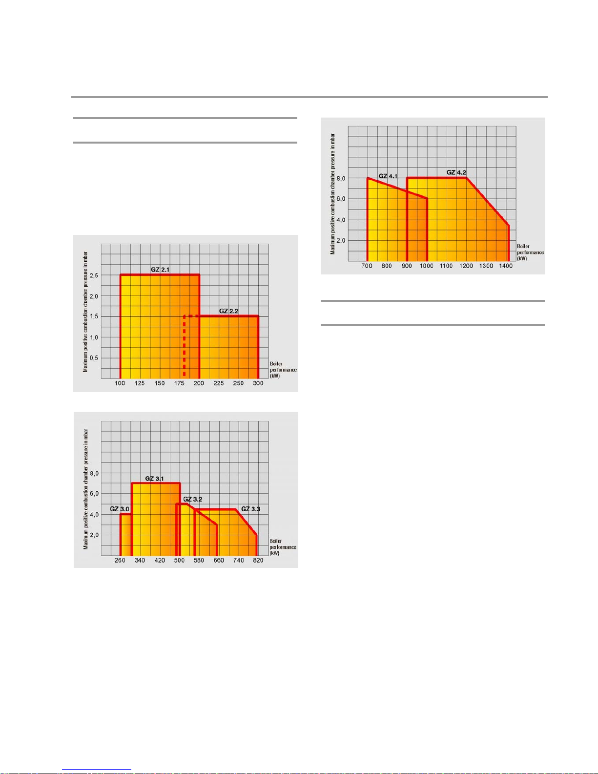
GZ 2 - GZ 4 / 100 - 1450 kW
4
Norms and regulations
The following standards and regulations are to be observed
during installation and operation of the burner.
HeizAnlV
Heating system ordinance
FeuVo
Firing ordinance of the German federal states
1. BImSchV
First ordinance for implementation of the German Emission Pro-
tection Law
VDI 2035
Guidelines for preventing damage from corrosion and scale
formation in hot water heating installations
VDE
Regulations and special requirements issued by the energy util-
ity companies
EN 303, part 1 and part 2
Heating boilers with forced draft burners
EN 60335, part 1
Safety of household and similar electrical appliances
DIN 4705
Calculating the dimensions of chimneys
DIN 4751
Hot water heating installations – safety requirements
DIN 4755
Oil firing installations – construction, execution, safety require-
ments
DIN EN 267
Automatic forced draught burners for liquid fuels – definitions,
requirements, construction and testing
DIN 51603, part 1
Fuel oils extra light
DIN 57116
Electrical equipment of firing installations
Please comply with the valid regional building code.
Exhaust system and effective heat demand
Boiler, burner and exhaust system (chimney) constitute an oper-
ating unit; account must be taken of low exhaust temperatures
when reducing the output
For exhaust temperatures below 160°C, the system must be de-
signed so as to avoid damage from condensation.
The uncondensed (humid) flue gas volume is an important indi-
cation of the size of the flue gas installations an chimneys re-
quired.
It is advisable to install draft limiters (supplementary air sys-
tems) to achieve stable combustion values under varying condi-
tions and to reduce possible humidity in the chimney. These
should be installed in the chimney where possible, to avoid pos-
sible noises in the flue pipe.
Modern conception
The gas burners in the GZ 2 - GZ 4 series are fully automatic
two-stage burners in monobloc design. They are suitable for
natural gas and liquefied gas according to DVGW paper G 260,
designed according to DIN 4788, and tested according to
DVGW and CE.
The burners are equipped with automatic gas firing units for in-
termittent operation as per DIN EN 298 or DIN 4788; automatic
gas firing units for continuous operation on request.
The GZ 2 - GZ 4 gas burners are pressurised burners with very
high impeller pressing and a steep impeller characteristic line.
Because of these features and the variable adjustment of the air
admission nozzle, these burners are appropriate for modern
high-performance boilers with reversible flames as well as for
older natural draught boilers. The modern conception of the
two-stage GZ 2 - GZ 4 burners with a maximum output range
of 50:100% (GZ 2 - GZ 3) or 60:100% (GZ 4) guarantees ideal
graduation of the two load-stages depending on operating
conditions.
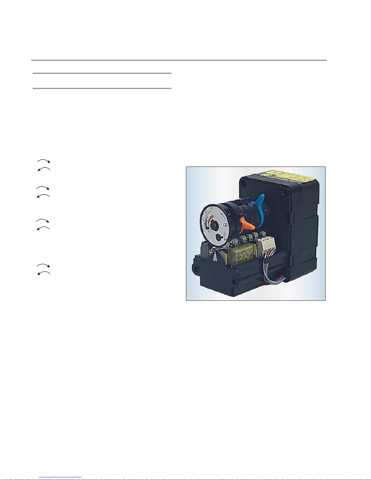
Useful design
Diecasting light metal case, power-dependent burner pipe and
high-performance mixing system, adjustable air admission noz-
zle and air damper servomotor for two-stage operation, A.C.
motor (GZ 2 - GZ 3.0) or threephase motor (GZ 3.1 - GZ 4), ig-
nition transformer, fan impeller, gas compact ramp (GZ 2 - GZ
3.0) or gas ramps assembly (GZ 3.1 - GZ 4), air pressure switch,
automatic firing sequence control with infrared flame detector
(GZ 2 - GZ 3) or ionisation flame control (GZ 4), internal plug
connections and plugs according to DIN 4791, mounting flange
with gasket and fastening screws.
Every burner is pre-tested.