Miatech Bio Turbo 6000 User manual

TECHNICAL INSTRUCTIONS
Bio Turbo 6000 User Guide
Specication Sheet ..........
Installation Guide. ...........
Layout Diagram. .............
Maintenance Guide ..........
Wiring Diagram..............
Pull Sheet ..................
JAN ,
AIRBORNE BACTERIA & ETHYLENE REMOVAL

MIATECH TECHNICAL INSTRUCTIONS | BIO TURBO USER GUIDE SPECIFICATION SHEET | JAN ,
Features
• LED’s for quick diagnostics
• Remote On and O control
• Easy service
• Easy changing of ozone plates and lters
• Four models for proper coverage
• Aluminum and Stainless Steel
generation chamber
• Easy to install and operate
• Low maintenance
Model BIO TURBO
Maximum volume up to ³ ( m³) per hours
Airflow CFM ( CMM)
Location Requirements
Electrical Source - VAC
Circuit breaker A
Maintenance
Air Filter Change every months
Ozone Plate(s) Change every months
Number of Ozone Plates
Specications
Dimensions:
Generation Chamber x x inches ( x x cm)
Catalytic Converter/
Controller x x inches ( x x cm)
Reaction Chamber x x feet ( x x cm)
Weight lb ( kg)
Construction
Materials:
Generation Chamber Aluminum
Catalytic Converter/
Controller Aluminum
Perforated Generator Plate Stainless Steel
Controls
Remote Control
Power Switch
Bio Turbo 6000
Specication Sheet
MIATECH TECHNICAL INSTRUCTIONS | BIO TURBO USER GUIDE INSTALLATION GUIDE | JAN ,
Bio Turbo 6000
Installation Guide
DESCRIPTION
The Bio Turbo is referred to, as the BT . The indicates
the amount of Cubic Meters the unit can properly control within a
hour period. The BT was designed to remove ethylene from
cold rooms and storage areas where fruits and vegetables are stored
in order to exteng their storage life.
TECHNOLOGY OVERVIEW
STAGE : AIR FILTER
The air lter removes dust and visual particles from the air.
STAGE : CELL DISRUPTER
An anti-microbial chemical is applied to the surface of a specically
designed substrate. This combination pierces and ruptures cell
membranes of airborne pathogens as they pass by, stopping the
normal life development of the cells. This stage can be especially
eective at controlling spores.
STAGE : OZONE CHAMBER
This chamber uses the positive eects of ozone to eliminate ethylene
gas while destroying up to .% of the bacteria and pathogens that
are being broken down during the previous stage. The ozone is safely
contained within the chamber providing a safe work environment.
STAGE : BIO CLEAN MODULE
In this nal stage, a catalyst is used to change the ozone into clean
oxygen. The catalyst creates a reaction that breaks down the ozone
molecule. From here the clean oxygen is released back into the
environment.
SYSTEM PLACEMENT
The Bio Turbo is designed to be mounted on the ceiling. Ethylene
rises, so the higher the units are mounted the better.
: position the Bio Turbo in a way to avoid direct air flow from
the coolers or fans to the air intake on a Generating Chamber.
A receptacle will be necessary to connect to either V AC or
V AC power.
: due to the dimension of the Bio Turbo system, we recommend
to have at least two installers.
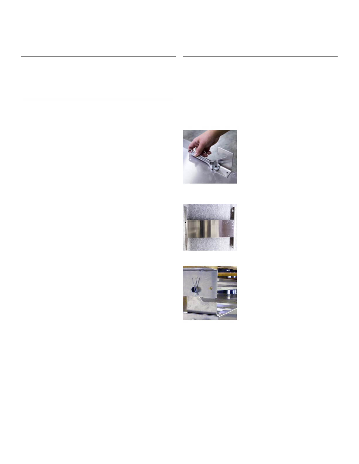
Picture 1
STEP : The large metal Reaction Chamber
should be mounted rst. The Chamber is
" ( cm) long and ." ( cm) wide.
Start with securing the mounting hooks with
bolts to the Reaction Chamber (see picture ).
Two wider hooks should be positioned
in the front part of the reaction chamber
(closer to Ozone Generation Box and
Control Box), two narrowed — on the back.
Make sure all hooks are pointed towards
the Ozone Generation Box and Control Box
(see picture , ).
You will nd L-brackets with mounting
holes for attaching to the ceiling (narrowed
side if the L-bracket) and holes for
long metal holding pipes (wider side
of the L-bracket). L-brackets should be
assembled together with a cross member
panel as it is shown on a picture .
When assembling pair of L-brackets, make
sure that the small holes on L-brackets,
right next to the holes for pipes, are
pointed toward the Ozone Genertion Box
and Controll Box – those holes are made
for the safety screws which go into the wide
front hooks (see picture ).
Picture 2
Picture 3
MIATECH TECHNICAL INSTRUCTIONS | BIO TURBO USER GUIDE INSTALLATION GUIDE | JAN ,
Bio Turbo 6000
Installation Guide
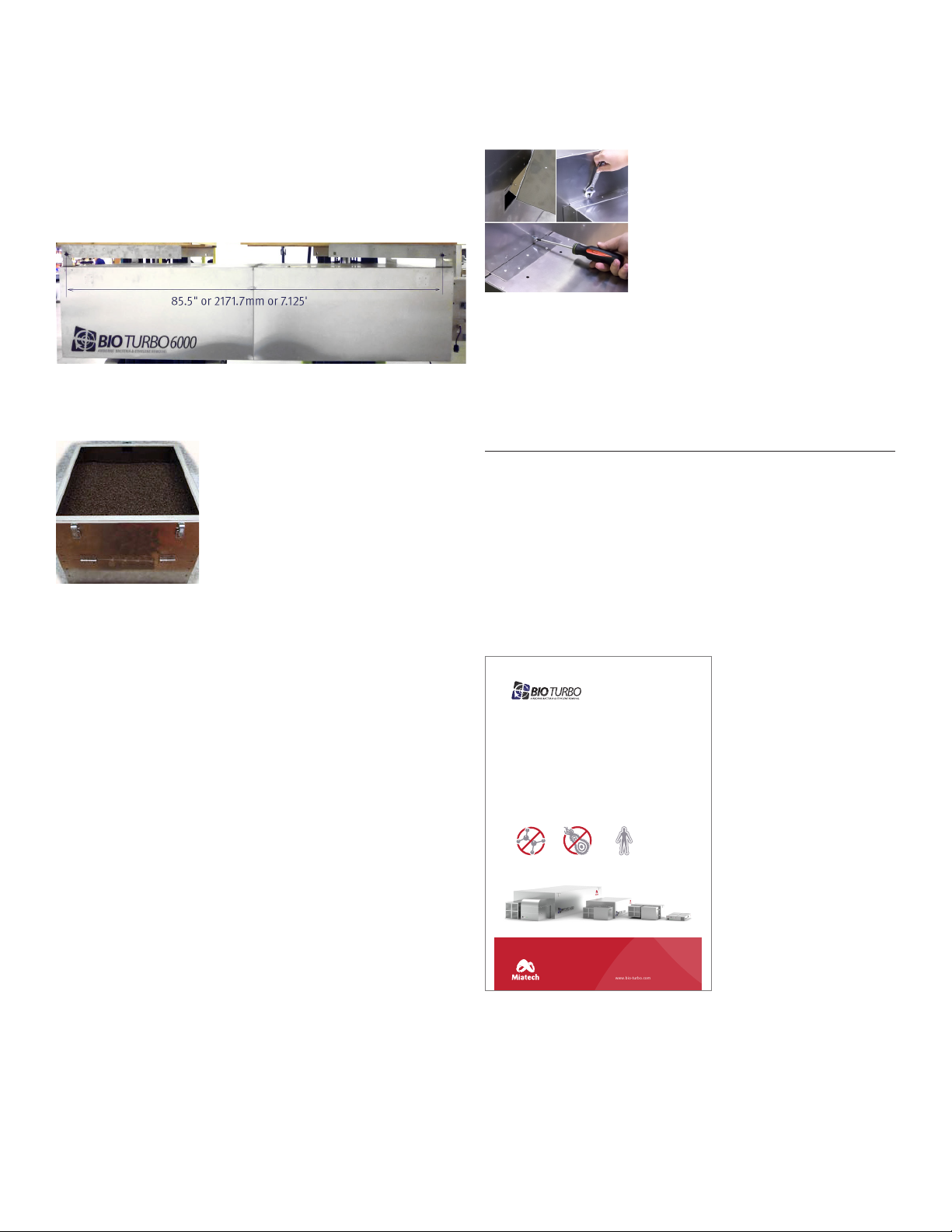
The distance between two long metal pipes on which the reaction
chamber has to be hanged on, should be .’’ or .mm or .’
(see picture ).
Mark on a ceiling the position of second pipe and attach the second
(rear) pair of L-brackets accordingly, to match the pipe holes as marked.
Aer attaching all L-brackets, inserting pipes and locking them with
pins – hang the Reaction Chamber as shown on picture .
Picture 5
STEP : The catalyst is in a separate
chamber of the Catalytic Converter. Simply
open the top section of the Catalytic
Converter and pour the catalyst into this
section. The required amount is supplied
in the BT Starter-kit (see picture ).
STEP : The Generation Chamber and the
Catalytic Converter should be mounted by
inserting them into the Reaction Chamber
(tilt the smaller boxes at an angle allowing
them to be placed into the Reaction Chamber slot) (see picture ).
Then screw the Generation Chamber and Catalytic Converter to the
Reaction Chamber (see picture ).
STEP : Plug the remote into the controller and route the remote box to
the desired location.
STEP : Plug power cord from Generation Chamber into the female
socket on the Controller Box.
STEP : Plug the detacheble power cord into
the male socket on the Controller Box and
the power supply receptacle. Either V
AC or V AC. The system’s operating
voltage is shown on the serial number label
on the side of the catalyst converter unit.
STEP : There should be two LED’s “glowing
green” on the Controller.
STEP : Turn “ON” the power switch on the
remote control. The other two LED’s should
“glow green” and then the fan should start. At this point, the system
will be fully operational.
STEP : The LED on the side on the Generation Chamber should be
“glowing green”.
The Generation Chamber should also emit a low hum indicating the
Generator plates are producing Ozone.
COUNTDOWN SERVICE TIMER
System is equipped with the Service Timer which is counting down
days to the next maintenance when system is operating. Timer is set
to days and when it gets down below days it starts beeping
and Service Red LED light on the controller box and the strobe light
on the remote control will flash, signaling maintenance is due.
Service Timer has to be reset back to days aer maintenance
is completed (see maintenance guide page for further instruction).
: please apply the BT Facility Entrance Label #25070, supplied in
a pack with system, near the facility entrance (see picture 7).
Picture 4
Picture 6
Picture 7
www.miatech.org www.bio-turbo.com
This storage is protected
with Miatech’s Bio Turbo.
Ethylene and bacteria removal technology.
KILLS BACTERIA HUMAN SAFEREMOVES ETHYLENE
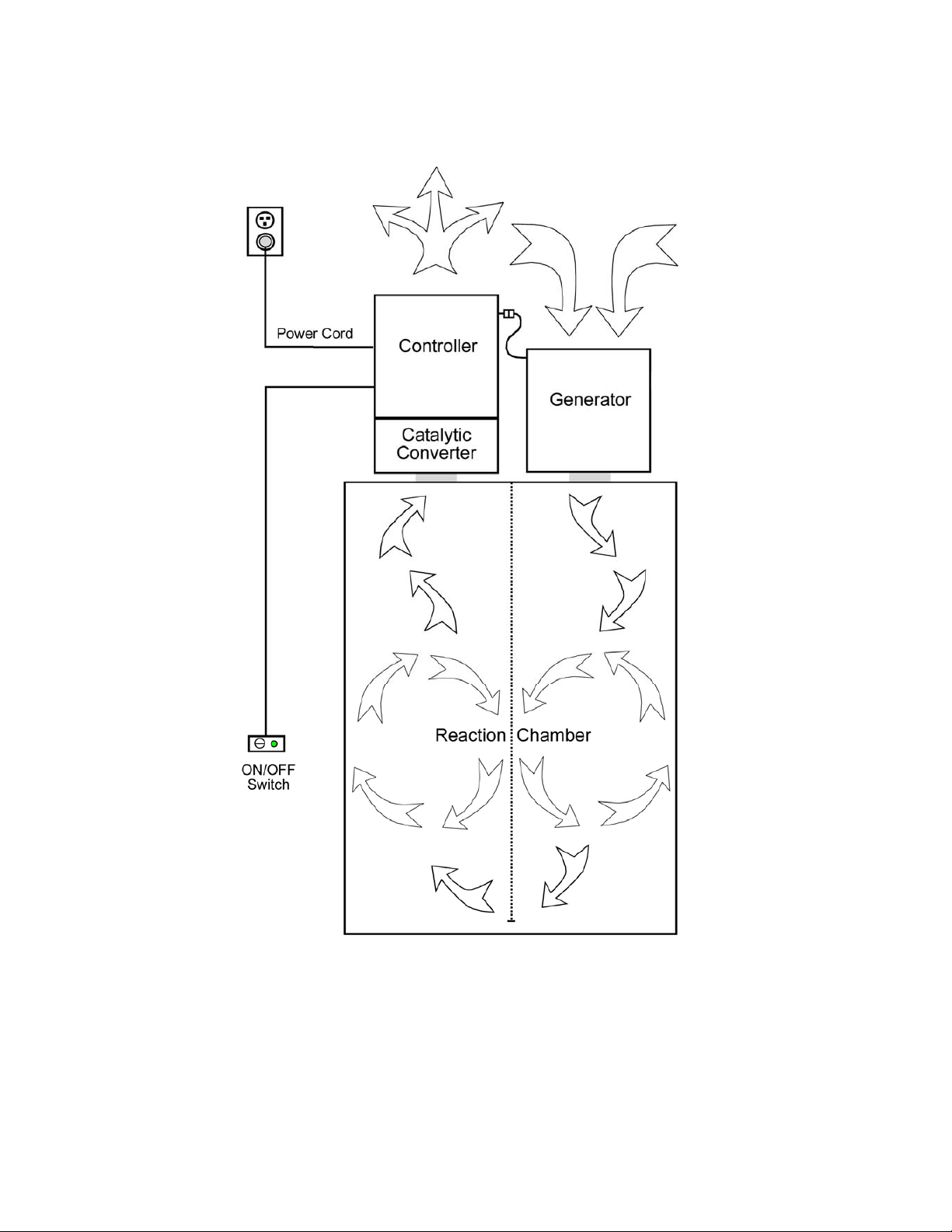
MIATECH TECHNICAL INSTRUCTIONS | BIO TURBO USER GUIDE LAYOUT DIAGRAM | JAN ,
Bio Turbo 6000
Layout Diagram
BIO TURBO 6000
Toll Free in North America:
1-800-933-6478
www.miatech.org
8AM-5PM PacificTime:
1-503-659-5680
June 2010
THE ADVANTAGE COUNTS
BIO TURBO 6000
LAYOUT DIAGRAM v. 1.2

MIATECH TECHNICAL INSTRUCTIONS | BIO TURBO USER GUIDE MAINTENANCE GUIDE | JAN ,
Bio Turbo 6000
Maintenance Guide
:
ALWAYS UNPLUG POWER BEFORE SERVICE!
Maintenance Requirements
Annual service requires the replacement of Ozone
Generation Plates.
Semi-annual service requires the replacement of Air
Filter (more oen if environment is very dusty).
To replace the Air lter and the Ozone Generator Plates:
• Unlatch the bottom cover on the Generation
Chamber and remove the Air lter (#).
: Slowly and carefully open the cover to ensure
the lter does not fall down. The door helps to secure it
in place.
• To replace the Generator Plates (#) release plastic
holders from the cassette, remove Generator Plates
and replace with new one. Fix plastic holders back
on place to secure Generator Plates.
System is equipped with the Service Timer (#) which
is counting down days to the next maintenance when
system is operating. Timer is set to days and when
it gets down below days it starts beeping and Service
Red LED light on the controller box will flash, signaling
maintenance is due. Service Timer has to be reset back
to days aer maintenance is completed.
To reset the Service Timer:
Carefully press and hold the button for about sec.
until numbers will start flashing. By releasing and
pressing again the same button select from
the options. Wait until it is dened (numbers will
stop flashing).
: a blunt object should be used to reset, so damage
won’t occur to the timer.
. Amp Breaker (#)
. V LED (#)
. Service V LED Red (#)
. LEDs V (#), V (#)
. BT service timer (#)
. Solid state relay (#)
. Airflow Safety Switch(#)
. Fan (#)
. V DC .A Power supply (#)
. Rocker switch (#)
. Strobe light (#)
. Air lter (#)
. Door Switch (#)
. Ozone transformer (#)
. Cell disrupter (#)
. Generator plates (#)
. BT Fuse Board (#)
. Timer Reset Hole
. Power Cord US plug (#) /
EU plug(#)
Diagnostic LED’s Name Description
“Power” (on the Remote Control) Power to the Main Switch
“Breaker” (on the Controller Chamber) Power to the Unit
“Power IN” (on the Controller Chamber) Power to the Power Supply
“ V” (on the Controller Chamber) Power to the Fan
“To the Generation Chamber”
(on the Controller Chamber)
Power to the Generation Chamber
“Service” (on the Controller Chamber) When the service is needed or when
protection triggered
Strobe Light (on the Remote Control) When the service is needed or when
protection has triggered
: If service Red LED comes ON along with strobe light, and timer is showing
more than 10 — the ozone generation current protection might be triggered. This
could happen due to the damage of ozone plates or power jump in power supply
network. Unplug the system and check the ozone plates. If this happened because
of power jump — restart the system by switching it OFF on a remote control and
put back ON aer 30 seconds.
: In case of frequent triggering of ozone
generation current protection, locate the
fuse board (#23290) inside the controller
chamber and put the jumper on two pins
(see picture 1).
Picture 1
Controller chamber
Remote control
Generation chamber
Controller chamber
Power cord

MIATECH TECHNICAL INSTRUCTIONS | BIO TURBO USER GUIDE WIRING DIAGRAM | JAN ,
Bio Turbo 6000
Wiring Diagram

Miatech Inc.
SE Lawneld Road
Clackamas, OR
www.miatech.org
For further technical support in North America call ---
If outside North America call to the USA at ---
Bio Turbo 6000
Pull Sheet Pack
PART NO. PART NAME AMOUNT INSP.
Catalyst Bio Turbo lb
BT K & K Hanging Bracket - Right Angle /" x /" x "
BT K Hanging Bracket - Panel " x " x "
BT K & K Hanging Bracket - Standard Hook Kit
(smaller le and right, larger le and right, total pcs.)
set
Mounting Angle Le Side
Conduit/Tube "
# x /" Self-tapping Tek Screw (Phillips)
/- x / Hex Head Cap Screw
Cable Tie " Black
- x / Phil. Screw
/" x Fender Washer
/" x " Threaded Rod
/ Lock Nut
/" Toggle Fastener
Cotter Pin /" x /" Zinc
N/A Remote with ' Cord
Foam Tape '
BT Facility Entrance Label
*See order for language
Power Cable ' g with female end
*See order for the plug
DATE PULLER
CHECKER
Table of contents
Popular Industrial Equipment manuals by other brands


Autz + Herrmann
Autz + Herrmann ROTOCLEAR S operating manual

Toshiba
Toshiba TH180 Maintenance manual

Baumer
Baumer HUBNER BERLIN Low Harmonics HOGS 75 Mounting and operating instructions

Honeywell
Honeywell MS-9200UDLS manual

APE
APE 400 VIBRO Operation and maintenance manual

SPEL
SPEL Vortceptor installation manual