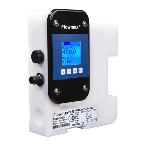
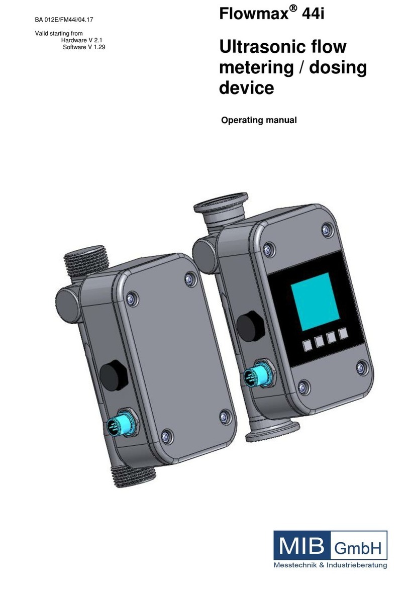
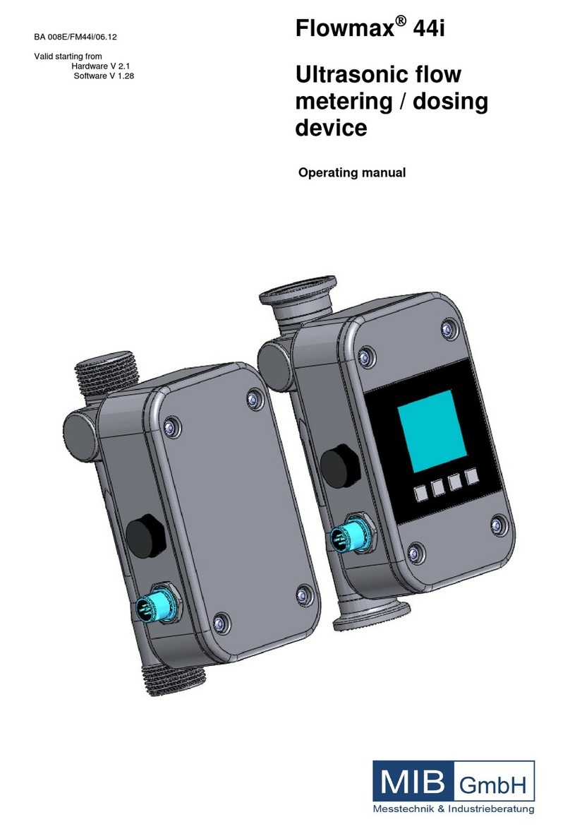
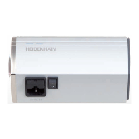
MIB Flowmax 44i User manual

Flowmax
44i
Ultrasonic flow
metering / dosing
device
Operating manual
BA 004E/FM44i/07.10
Valid starting from
Hardware V 2.1
Software V 1.25

Flowmax
44i General safety instructions
M I B 2
General safety instructions
Please always observe the following safety instructions!
Intended use
• The flow meter Flowmax 44i may only be used for measuring the flow of
pure, homogeneous liquids.
• The volume flow meter Flowmax 44i is built operationally safe according to
the latest state of the art takes the relevant regulations according to EN
61010 (corresponds to VDE 0411 “Safety specifications for electrical
measurement, control and laboratory devices”) into consideration.
Please pay attention to the safety
instructions with the following
pictograms in these operating
instructions:
• The manufacturer cannot be held liable for any damage from inappropriate
or unintended use. Conversions and/or changes to the flow meter may only
be made, if they are expressly admissible according to these operating
instructions.
Personnel for installation, commissioning and operation
• Assembly, electronic installation, commissioning and maintenance o fthe
flow meter must be carried out by qualified personnel authorized by the
operator of the plant. The qualified personnel must have read and
understood these operating instructions and must follow its instructions.
• The installer has to ensure that the flow meter is correctly connected
according to the electric connection diagrams.
Technological progress
The manufacturer reserves the right to adapt the technological specifications to
state of the art technological developments without special prior notice. Further
information about the latest updates and potential additions to these operating
instructions are available from MIB.
Note! Attention!
Warning!
Warning!

Flowmax
44i Tablet of contents
M I B 3
Tablet of contents
Page
General safety instructions 2
1. Planning information 4
1.1 Area of application 4
1.2 Measuring principle 4
1.3 Dosing function 5
1.4 Operational safety 5
2. Assembly and installation 6
2.1 Installation instructions 6
2.2 Assembly of the flow meter 7
2.3 Electrical wiring 9
3. Commissioning 11
3.1 Operation 11
3.2 Functionalities of flow meter and default settings 12
3.3 Overview of default settings 19
3.4 General information 19
4. Exchange of measuring device 20
5. Technical specifications 21
5.1 Dimensions and weight 21
5.2 Technical specifications 24
6. Accessories 25
7. Shipment 25
8. Order code 26

Flowmax
44i 1. Planning information
M I B 4
1. Planning information
1.1 Areas of application
The flow measurement device Flowmax 44i is in particular suited for measuring
dynamic events in pipes and tubes. Liquids are measured. It is used among
others in
• Chemicals supply for controlling, logistics, monitoring
• Filling machines in food industries
• Cooling systems, logistics, monitoring
• Production machinery for control and monitoring of formulas
• Valve control for continuous release of liquid volumes
• Supply with de-ionized water
• Very dynamic processes with dosing times of below 1 second
It has the following characteristics:
• No movable parts and therefore no wear
• High repeatability
• Easy to clean
• Safe manipulation
• Compact design
• Integrated detection of empty conduits
• Integrated dosing function with possibility of pre-setting and adjusting
amounts
• Chemical resistance
• Integrated display with keypad
1.2 Measuring principle
It usually takes more energy to swim against the flow than with the flow. The
ultrasonic flow measurement according to the phase-difference procedure is
based on this simple physical fact:
Two sensors that are located opposite from each other alternatingly transmit
and receive ultrasonic signals. With medium at standstill both sensors receive
the transmitted ultrasonic signals in the same phase, i.e. without phase
difference. With medium flowing there is a phase shift. It differs when measured
in direction of the flow from when measured against the direction of the flow.
This phase difference is directly proportional to the flow rate. The flow rate and
the known diameter of the pipe are used to determine the flow volume.
Fig. 1: Presentation of the principle of ultrasonic flow measuring

Flowmax
44i 1. Planning information
M I B 5
1.3 Dosing function
Dosing can basically be realized in different ways:
1. Flowmax 44i as dosing device (dosing control via Flowmax 44i, for 8-Pin
option)
Flowmax 44i does the entire dosing control. The dosing quantity (e.g. 400
ml) is pre-set in the Flowmax 44i via the digital interface (RS485) with the
operating software. Dosing starts, as soon as line start of dosing is wired to
24 V, e.g. via a pushbutton. Flowmax 44i will now open the dosing valve via
the output configured for it. When the pre-set dosing quantity is reached,
the dosing valve is closed via the above output. The 2nd output can be
used independently for signalling of empty pipe detection, limit control or
flow direction.
2. Flowmax 44i as dosing device (dosing control via FlowSoft )
Flowmax 44i does the entire dosing control. The dosing quantity (e.g. 400
ml) is pre-set in the Flowmax 44i via the digital interface (RS485) with the
operating software. Dosing starts via the dosing-menu in the operating
software. Flowmax 44i will now open the dosing valve via the output
configured for it. When the pre-set dosing quantity is reached, the dosing
valve is closed via the above output.
3. Flowmax 44i as flow meter (dosing control via dosing equipment)
The dosing equipment is responsible for the entire dosing control.
Therefore, the dosing quantity is fixed in the dosing equipment control
during commissioning by pre-selecting the meter pulses. Dosing starts,
when the relevant pushbutton of the dosing equipment is pushed. The
control will now open the dosing valve. From now on Flowmax 44i will send
a voltage pulse to the control for each volume unit that has flown through
(e.g. per 1ml). When the pre-selected pulse quantity is reached, the control
closes the dosing valve. In this case, output 1 is used to send out pulses.
1.4 Operational safety
Comprehensive self-tests ensure highest possible operational safety.
The protection class is IP 67.
Flowmax 44i meets the general EMC immunity requirements according to CE,
EN 50081-2, and EN 50082-2.
Concerning the low voltage directive Flowmax 44i meets the safety
requirements according to EN 60601-1.

Flowmax
44i 2. Assembly and installation
M I B 6
2. Assembly and installation
2.1 Installation instructions
The housing of Flowmax 44i shows an arrow symbolizing the direction of the
flow measurement. The flow meter has to be installed in a way so that the flow-
through is in direction of the arrow.
TOP -> outlet
DOWN -> in feed
Fig. 2: Installation position of Flowmax 44i
For fastest possible gas detection it is important to keep the pipe distance from
tank to Flowmax 44i should be kept as short as possible. Accurate
measurement can only be guaranteed, if the pipe is completely filled and if it is
ensured that the liquid does not outgas.
Notwithstanding it may be advantageous for dosing applications to place the
Flowmax 44i as close as possible to the dosing valve, since tubes increase their
cross-section depending on the system pressure. This may lead to repeatable
differences.
Please note that it is absolutely necessary to have a back pressure of at
least 0.3 bar rel. (corresponds to 3 m water column) at the outlet of the
Flowmax 44i.
Solid matter particles that are carried along may result in measuring errors.
When using pumps, Flowmax 44i must be installed in flow direction behind the
pump, on the pressure side, in order to ensure sufficient pressure. Regard the
maximum pressure step of the Flowmax 44i.
For correct volume flow measurements straight and unobstructed inflow and
outflow zones for Flowmax 44i have to be observed. Starting from the
connection thread these have to be at least:
DN 10 DN15 DN20 DN25
Inflow track 10cm 30cm 50cm 80cm
Outflow track 0cm 5cm 10cm 20cm
Attention!
Attention!
Attention!

Flowmax
44i 2. Assembly and installation
M I B 7
2.2
Assembly of the flow meter
The flow meter gets mounted into a pipe system by using the connection
piece. To grant best measuring performance Flowmax 44i should be mounted
vertically into the pipe. It is not recommend to place the flow meter after a
dosing-vlave, in this case the flow meter can run empty. This causes a
measuring deviation at the next measurement. To avoid getting bubbles in the
liquid, Flowmax 44i should be installed on the pressure side of the pump.
Fig.3: Mounting examples for Flowmax 44i
If it is not possible to mount the flow meter vertically, then the pipe where the
device is mounted haves to be filled with liquid. The best measuring result is
reached, when bubbles are not able to get into the Flowmax 44i.
Fig.4: Mounting possibilities
Note!
Note!

Flowmax
44i 2. Assembly and installation
M I B 8
Vibrations or mechanic forces may decrease the measuring accuracy.
It is possible to fix the flowmeter additionally with two clamps against vibrations
or movements. Use the clamps as seen in the figure below at the inlet and
outlet of Flowmax 44i.
Fig.5: Fixing Flowmax 44i
Applications with hot liquids:
When Flowmax 44i is used in applications with liquid temperatures higher than
60°C and is mounted horizontal it is recommend to m ount the flowmeter with
the electronic housing on the lower side. The stress for the electronic is
reduced because the heat is able to rise up. When Flowmax is mounted vertical
it makes no different on which side the housing is.
Fig.6: Flowmax 44i with hot media
Note!
Attention!

Flowmax
44i 2. Assembly and installation
M I B 9
2.3 Electrical wiring
The flow meter must not be installed, wired or disassembled when live
(operating voltage). For any of these activities interrupt power supply of
Flowmax 44i.
Fig.7: Pin code: Connection plug / socket
Connector cable configuration with outlets defined by manufacturer.
The outlets may be re-programmed for specific applications.
Pin Function Description
1 L+ Voltage supply: 18...30 VDC
2 Pulse
alternative:
1. Empty-pipe output
2. Dosing output
3. Limit-control output
4. Negative flow
Digital Output 1 (O1)
Freely adjustable ranging from 0.1 to 25
ml/pulse in 0.1 ml/pulse steps, npn-
Transistor, max. load 30V/100mA.
Configurable output of 0V or 24V when pipe
is empty.
Configurable output of 0V or 24V via dosing-
menu by FlowSoft.
Configurable output of 0V or 24V when
reaching upper or lower limit
Configurable output of 0V or 24V when liquid
flows in negative direction
3 GND Ground: 0 V
4 Communication Communication interface
5 Analog output
4....20mA; 0....20mA
Example: 0l/min => 4mA
36l/min => 20mA
Alert => 2mA
(4-20mA, depending on the configured limits)
Attention!

Flowmax
44i 2. Assembly and installation
M I B 10
Fig.8: Pin code: Connection plug / socket
Connector cable configuration with outlets defined by manufacturer.
The outlets may be re-programmed for specific applications.
Pin Function Description
1 L+ Voltage supply: 18...30 VDC
2 Pulse
alternative:
1. Empty pipe output
2. Dosing output
3. Limit control output
4. Negative flow
Digital Output 1 (O1)
Freely adjustable ranging from 0.1 to 3000
ml/pulse in 0.1 ml/pulse steps, npn-Transistor,
max. load 30V/100mA.
Configurable output of 0V or 24V when pipe is
empty.
Configurable output of 0V or 24V via dosing-menu
by FlowSoft.
Configurable output of 0V or 24V when reaching
upper or lower limit
Configurable output of 0V or 24V when liquid flows
in negative direction.
3 GND Ground: 0 V
4 Digital Output 2
Functions:
1. Empty pipe output
2. Dosing output
3. Pulse output
4. Limit control output
5. Negative flow
Digital Output 2 (O2)
Configurable npn- or pnp-Transistor, max. Load
30V/ 100mA.
Configurable output of 0V or 24V when pipe is
empty.
Configurable output of 0V or 24V via dosing menu
of FlowSoft.
Freely adjustable ranging from 0.1 to 3000
ml/pulse in 0.1 ml/pulse steps.
Configurable output of 0V or 24V when flow
reaches upper or lower limit.
Configurable output of 0V or 24V when liquid flows
in negative direction.
5 Analog +
4....20mA; 0....20mA; 0....10V
Example: 0l/min => 4mA
36l/min => 20mA
Alert => 2mA
(4-20mA, depending on the configured limits)
6 Communication Communication interface
8 Shielding EMC safety
7 Digital input 1
1. Dosing output
2. Set offset
3. Creeping flow
Digital input 1 (I1)
Starts the dosage by a rising edge of 24V.
The Offset is set by a rising edge of 24V.
Creeping suppression is deactivated as long as
there are 24V at the input.

Flowmax
44i 3. Commissioning
M I B 11
3. Commissioning
Attention:
While commissioning take care to run the Basic Trim (FlowSoft
Medium) with filled advice. Repeat this action until amplifier stage and
receiving amplitude reach a steady value.
3.1 Operation
If Flowmax 44i is used as volume flow meter for water or water-like liquids
according to section 1.3.2, it will not require on-site manipulation, because the
following parameters set by the manufacturer will guarantee optimum
functionality. Notwithstanding the Flowmax 44i may also be supplied with
customized settings. The coordination must be done with the purchase order.
If necessary, e.g. if viscosity and/or speed of sound deviate strongly from
water, the pre-set parameters can be individually adjusted with the help of the
integrated interface and the FlowSoft service software. This is always
necessary when using Flowmax 44i as a dosing device according to section
1.3.1. This requires the USB to RS485-Converter Sonic.
The following parameters may be changed to settings suitable for the
individual conditions: for 5-pin version
- Digital output 1 (O1), function and behavior
- Analog output
- Flow range, for which shall apply 4...20 mA
- Pulse value
- Creeping suppression
- Optimization of measurement curve with up to 8 interpolation values
(medium matrix)
The following parameters may be changed to settings suitable for the
individual conditions: for 8-pin version
- Digital output 1 (O1), function and behavior
- Digital output 2 (O2), function and behavior
- Digital input 1 (I1)
- Analog output
- Flow range, for which shall apply 4...20 mA
- Pulse value
- Creeping suppression
- Optimization of measurement curve with up to 8 interpolation values
(medium matrix)
Among others, see FlowSoft operating instructions
Attention!
Attention!
Note!

Flowmax
44i 3. Commissioning
M I B 12
3.2 Functionalities of flow meter and default settings
Display and user menu
Flowmax 44i is equipped with a display to visualize actual measuring values
and change parameters of the flow meter. The navigation all over the menus is
done by the four keys on the keypad.
When the “Set” key is pressed the device switch into the main menu. Different
menu options can be selected by using the two arrow keys.
To enter e.g. analog limits “Analog output – Upper limit” use the arrow keys to
change values and press “Set” to confirm. To switch back to the last menu level
press the “Esc” key. As soon as the operator tries to changes values it is
needed to enter a password. Password protection is used to ensure that just
authorizes personal is able to change values or configurations. The default
password for Flowmax 44i is 41414. The password can be changed with
service tool FlowSoft.
Note that not all functions of Flowmax 44i can be changed by the user menus
of the display. To configure more parameters the service software FlowSoft and
an USBtoRS485-Converter Sonic is needed.
Attention:
Described functions that are marked with * are only available for the Flowmax
8-pin version. Flowmax 44i without user display supports the same functions
like the display-version. To change configurations at Flowmax 44i without user
display an USBtoRS485-Converter Sonic and the service software FlowSoft is
needed.
Note!
Attention!

Flowmax
44i 3. Commissioning
M I B 13
Fig.9: Menu organization for 5-pin version

Flowmax
44i 3. Commissioning
M I B 14
Fig.10: Menu organization for 8-pin version

Flowmax
44i 3. Commissioning
M I B
15
Set Offset
In the sub menu “Offset” it is possible to set the actual offset of the flow meter.
This function should just be used when Flowmax 44i is completely filled with
liquid and there is no flow.
A small offset change e.g. caused by variable temperatures is automatically
done by the flow meter. It is also possible to set the offset via the configurable
digital inputs.
Language
The language of the display can be changed. Available languages are English
and German.
Filter
The function „Filter“ determines the average determination of the analog output
signal. Possible configurations : Soft, Medium, Strong, Off
The analog output signal reacts faster to signal changes
when average
determination is soft. Whereas the output signal reacts slower when average
determination is strong.
Unity
Flowmax 44i is able to show actual flow or the volume in different unities.
Following unities can be selected:
ml/s + l , Gal/min +Gal , l/min + l , l/min + m³.
The first letters correspond the unity of the flow value. The letters after the +
correspond the unity of the volume value.
Reset Counter
The volume counter of Flowmax 44i can be reseted. Note, accidentally erased
counter values are permanent lost. After doing a reset the counting works
normal.
Basic Trim
This function makes sure that the flow meter is conforming to the media
specific characteristics. Through execute this function Flowmax 44i runs a self
configuration which optimises all important parameters. This process may last
app. 1 minute.
To make sure the basic trim is correctly done the flow meter has to be filled with
liquid without a flow.
When there is an error detected while doing the basic trim the display shows
“Error”. After successful finishing the function basic trim the display shows
“Done”.
Attention!
Note!
Note!
Attention!

Flowmax
44i 3. Commissioning
M I B 16
Creeping suppression
The creeping suppression serves the purpose of excluding flows from the
measurement that can evolve through convection in a narrow frame around zero,
even with a closed valve. At the factory, the creeping suppression is set at a
reasonable standard value in relation to the cross-section of the flow meter.
There are higher tolerances below the standard default settings, see also section
5.2, measurement errors!
The creeping suppression works with a hysteresis of ±25%.
Fig.11: Function of the creeping suppression illustrated with 0.6 l/min
Example: Creeping suppression = 0,6 l/min
If the flow rate is lower than 0.45 l/min the pulse output/analog putput
becomes inactive. If the flow rate exceeds 0.75 l/min a pulse is output
again and added to the quantity counter. Similarly, a value is
transmitted to the analog output again.
Setting range: 0,0...20 l/min, in 0,006 l/min steps
Default settings: 0,3 l/min for DN10
0,9 l/min for DN15
3,5 l/min for DN20
5,0 l/min for DN25
Diagnostic
The sub menu „Diagnostic“ shows the actual software/hardware version and
many helpful values for analysis. Knowing about the actual values or the state
bits makes it easy to review the measurement by the manufacturer.
Note!
Attention!

Flowmax
44i 3. Commissioning
M I B 17
Analog output
The analog output is available as current output 4-20mA or 0-20mA. Type
depending on purchase order. As a standard it comes with current output 4-
20mA. It can also be switched off with by using the display menu or FlowSoft
operating software. This reduces the need of current of the Flowmax 44i.
The current output outputs flows from 0 to 22mA as measure for the flow or the
state of the measuring pipe.
The values here signify for 4-20mA configuration:
20 mA the upper limit of the relevant measuring area
4 mA the lower limit of the relevant measuring area
3,8mA undershoot the lower limit
22 mA overshoot the upper limit
2 mA empty pipe
Upper and lower limit parameters can be set freely within the type-specific
measuring areas of the device. By default zero flow is set at 4 mA and the
respective maximum flow is set at 20 mA.
Setting range: 0-20mA, 4-20mA, off
When current output is used make sure the load is not higher than
500Ohm. A higher load may cause the device can not provide the
maximum current of 22mA.
Pulse value
This determines for what flow volumes an output pulse will be emitted.
Choose configuration such as to neither exceed the maximum ouptput
frequency of the Flowmax 44i (10kHz) nor the maximum input frequency of the
control.
Example: 2,0 ml/Pulse
This means: a pulse is emitted every 2.0 ml.
Setting range: 0,1...3000,0 ml/Pulse, in 0,1 ml/Pulse steps
Default setting: 1,0 ml/Pulse
Note!
Attention!
Attention!

Flowmax
44i 3. Commissioning
M I B 18
Digital output 1
Digital output 1 may be used as pulse output, empty pipe detection, for
switching dosing valve or limit control. By using FlowSoft or the Display it is
possible to switch between npn and pnp-transistor logic. In case of inductive
load a freewheeling diode has to be connected parallel to the coil.
Flowmax 44i npn-out connected to a counter
Fig.12: Connecting output 1 to external counter
Setting area: off, pulse output, empty pipe, dosing output,
lower limit, upper limit, negative flow
Digital output 2 *
Digital outputs 2 may be used as pulse output, empty pipe detection, for
switching dosing valve, limit control or flow direction control. See chapter 2.3
table connection plug 8-pins.
The npn or pnp logic can be chosen . When the output is connected to a
inductive consumer a free-wheeling diode has to be installed parallel to the
load.
Flowmax 44i pnp-out connected to a relay
Fig.13: Connecting output 2 to relay
Setting area: off, pulse output, empty pipe, dosing output,
lower limit, upper limit, negative flow
Note!
Note!

Flowmax
44i 3. Commissioning
M I B 19
Media
Flowmax 44i dispose of a medium matrix with up to 8 interpolation values.
Different medias can be managed in the sub menu “Media”. Matrix values can
be saved and if needed be loaded for different medias.
Digital input 1 *
Flowmax 44i has two digital inputs that are programmable to following
functions: dosing input, set offset, creeping suppression inactive. In order to
start a dosing process, wiring to 24V DC is required. The condition is the
configuration of the dosing parameters with the FlowSoft service software via
the USB to RS485 Converter Sonic.
Dosing input is debounced so that re-start is not possible during a running
dosing process.
Not all of the following functions are adjustable via the user display. See
chapter 3.2 Fig.9 and Fig.10: Menu organization.
3.3 Overview of default settings
Function Default settings
Digital output 1 (O1) Pulse output
Digital output 2 (O2) * Empty pipe output
Digital input 1 (I1) * No function assigned
Current output 4-20mA
Pulse value 1 ml/Pulse
Creeping suppression 0,3 l/min
0,9 l/min
3,5 l/min
5,0 l/min
3.4 General Information
Please check the following before switching on the flow meter for the first
time:
• Check the electrical connections and cable allocations.
• Check the installation position of the flow meter. Are the direction of the
arrow on the housing/name plate and the actual flow direction in the pipe
congruent?
• Is the measurement pipe completely filled with fluid?
• Check the back pressure in the system.
When everything has been checked and the relevant conditions are met
switch on power supply. After a time period of 30 minutes with running power
supply the measuring device reaches the maximum of accuracy.
Now, Flowmax 44i is operational!
Note!
Note!
Attention!
Attention!

Flowmax
44i 4. Exchange of flow meter
M I B 20
4. Exchange of measuring device
• Switch off power supply before disconnecting the electrical connections
• Please note that after exchanging of the flow meter
a) potentially the programming of the previous flow meter should be taken
on.
b) a SET quantity has to be set when using the dosing function.
If a change of the configuration of the device is necessary, the FlowSoft
programming software and a USBtoRS485-Converter as well as a PC are
required (see section 6. Accessories).
Repair, hazardous substances
Before sending the flow meter Flowmax 44i to MIB for repair, the following
measures have to be taken:
• Remove any adhering residues of the medium. Fully rinse measuring pipe.
Please pay special attention to the area of the process fittings to which
residues of the medium to be measured may adhere. This is particularly
important, if the medium to be measured is health hazardous.
Not or just insufficient cleaned devices will be returned to the sender for
cleaning without having been checked.
• Please send a note with the flow meter with a precise description of the
error, the application as well as the physical-chemical properties of the
medium to be measured.
The owner of the flow meter will be charged for costs incurred because of
inadequate cleaning of the flow meter, for potential disposal or personal injury
such as chemical burns etc.
In order to be able to process your repair order fast and smoothly it is important
that you name a contact person including phone and fax number as well as e-
mail address, who is able to answer potential technical questions of our service
and support staff.
Attention!
Attention!
Attention!
Attention!
Note!
Note!
Other manuals for Flowmax 44i
2
Table of contents
Other MIB Measuring Instrument manuals
