Qualitrol 509-200 User manual

Electronic Cooling
Monitor for Liquid-Filled
Transformers
509-200
Operations Manual
IST-072-2

QualiTROL
Electronic Cooling Monitor for
Liquid-Filled Transformers
Operations Manual

ECN-27433 August 25, 2009
i
Overview ______________________________________________________________1
QualiTROL Electronic Cooling Monitor..............................................................................1
QualiTROL..............................................................................................................................2
About This Manual .................................................................................................................2
Controls, Indicators, and Modules _________________________________________3
Front Panel...............................................................................................................................3
Modules ....................................................................................................................................4
509-RTD Input Module ......................................................................................................4
509-CT Input Module.........................................................................................................4
509-AC Voltage Input Module...........................................................................................4
509-Potentiometer Input Module........................................................................................4
509-DC Voltage Input Module...........................................................................................5
509-Current Input Module..................................................................................................5
509-Dry Contact Closure Module.......................................................................................5
509-Powered Contact Closure Module...............................................................................5
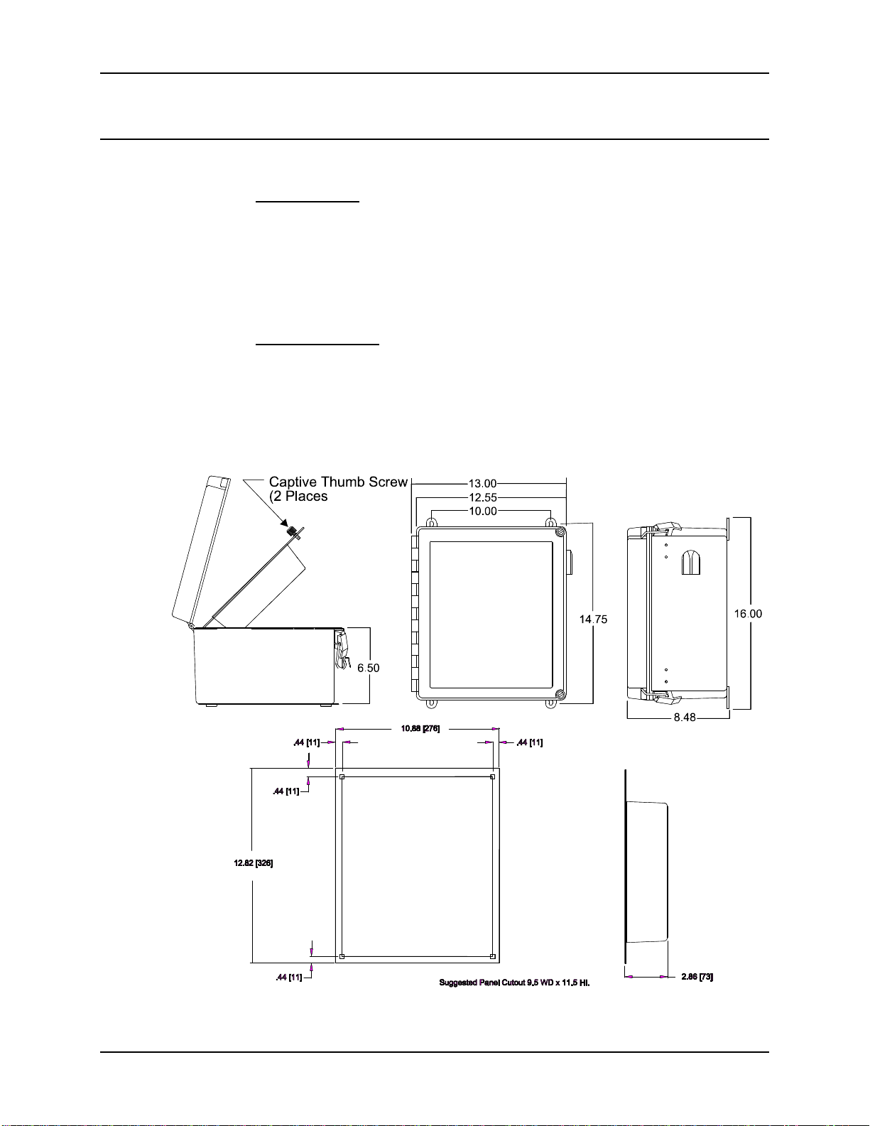
Installation_____________________________________________________________6
Location and Mounting...........................................................................................................6
Power Supply...........................................................................................................................7
Heater Option..........................................................................................................................9
RTD Input Module................................................................................................................10
CT input Module...................................................................................................................11
AC Voltage Input Module.....................................................................................................11
Potentiometer Input Module................................................................................................11
DC Voltage Input Module.....................................................................................................12
Current Input Module ..........................................................................................................13
Dry Contact Closure Input Module.....................................................................................14
Powered Contact Closure Input Module.............................................................................14
Output Contacts ....................................................................................................................14
Remote Output Signals.........................................................................................................15
Communications....................................................................................................................16
Operation_____________________________________________________________18
Automatic Operation ............................................................................................................18

ECN-27433 August 25, 2009
ii
Viewing Channels (Viewing Mode Scrolling) ..................................................................18
Menu Mode.......................................................................................................................18
Program Mode ..................................................................................................................20
Cooling System Monitor_________________________________________________20
Testing the System.................................................................................................................22
Functional Specification_________________________________________________23
Appendix _____________________________________________________________24
Configuration Records __________________________________________________30

1
QualiTROL
Electronic Cooling Monitor for
Liquid filled Transformers
Operations Manual
OVERVIEW
QualiTROL Electronic Cooling Monitor
The QualiTROL Electronic Cooling Monitor (ETM) for Liquid-Filled
Transformers (Model #509-200 Series) is an Intelligent Electronic Device (IED).
Combining microprocessor technology and advanced digital signal processing, to
accurately assess the health, and performance of three phase or autotransformers.
The 509 can be tailored to suit the application. The ETM can monitor up to eight
total parameters. Requiring inputs from Resistance Temperature Detectors
(RTD’s), Current Transformers, AC Voltage (0-140 or 0 –320 VAC), Current
loops (0-1 or 4-20 ma DC), DC Voltage (0-100 mv or 0-10V), or Switch Contact
Closure, this complete transformer monitoring system can monitor parameters
such as: Liquid Temperatures (Main Tank Top or Bottom, Load Tap Changer),
Winding Temperatures, Ambient Temperatures, Winding Current, Cooling Bank
Currents, and a variety of parameters from transducers such as Tank Pressure, or
Dissolved Gas in Oil analysis. The 509 Transformer Monitor offers:
Advanced thermal modeling of winding temperatures
Superior temperature control for higher loads
Integrated Load Tap Changer temperature monitoring
Stand alone or networked substation monitoring
Diagnostic tool for condition based maintenance
Eight (8) form C adjustable relays to operate cooling equipment, signal
alarms, and provide trip functions, depending on transformer conditions
Up to four (4) 0-1 or 4-20 ma DC loops for use with SCADA systems
Digital communication ports RS-232, RS-485
The device is extremely easy to install and use. It is designed to be mounted
outdoors (heater available inside enclosure), in the transformer control cabinet or
in a 19 inch control rack and is powered by a universal power supply of 90-264
VAC 47-63 Hz single phase power or 40-290 VDC. It comes with user-friendly

Electronic Cooling Monitor
2
computer aided setup software, and can be supplied with non-intrusive, easy to
retrofit sensors.
QualiTROL
QualiTROL has been a leader in supplying pressure, liquid level, and
temperature controls since 1945. An ISO 9001 system certified company, we are
committed to providing you with quality and reliability, both in our products and
in our service.
About This Manual
This manual provides all the information you will need to configure, install, and
operate your QualiTROL Electronic Transformer Monitor. It is organized into
the following sections:
Controls, Indicators, and Modules — Diagrams and brief descriptions to help
you locate and understand basic functions of each of the controls, indicators, and
modules that make up the QualiTROL ETM.
Installation — Step-by-step, illustrated instructions to guide you through
mounting, supplying power to, and wiring your Transformer Monitor.
Operation — A description of automatic operation, as well as easy instructions
on how to view parameters, and set points, reset memories, program the ETM
using the Keypad, and test the system.
Functional Specification — A detailed functional specification of the unit.
Appendix — A functional wiring diagram for your reference, an example of the
front panel menu diagram, a rear cover view and a Configuration Table in which
to record settings and connections to the ETM.

Electronic Cooling Monitor
3
CONTROLS,INDICATORS,AND MODULES
Front Panel
The functions of the display and the keypad on the Front Panel are described
below. For operating instructions, refer to the “Operation” section.
DISPLAY — Automatically scrolls through the channels and displays the
channel name and the value of the parameter every 2 seconds. Also used to
display the selected indications of the keypad control.
Keypad — The ENTER key is used to change menu modes or accept changes to
values, the TEST key displays the setpoint source and value on the DISPLAY, the
MENU key is used to access the programming menu, The RESET key is used to
reset the maximum and minimum values (while in the program menu) The
ARROWS keys are used to move around in the various menus. For a full
operation description, refer to the “Operation” section.
Set Point Indicators — A red LED illuminates to indicate that the set point for
the relay indicated on the overlay has been exceeded.
RS-232 Port —When used with the QualiTROL software, this port allows for
the setup of all of the parameters of the Transformer Monitor. See Software
Manual for a full description of this set up procedure.

Electronic Cooling Monitor
4
Modules
The modules comprising the QualiTROL ETM include:
509-RTD Input Module
509-CT Input Module
509-AC Voltage Input Module
509-Potentiometer Input Module
509-DC Voltage Input Module
509 Current Input Module
509-Dry Contact Closure Module
509-Powered Contact Closure Module
This section describes the function and key components of each of these
modules.
509-RTD Input Module
RTD Input Modules are provided for monitoring Liquid, Ambient or if used in a
heated well, winding temperatures. The input to the module is either a 10 ohm
copper or a 100 ohm platinum RTD(factory configured).
For measuring Liquid or Ambient temperatures the Module is scaled over the
range of –40°C to 120°C. If it is used in a heated well then the scale is –40° to
200°C. This needs to be specified when ordering the 509 unit from the factory.
509-CT Input Module
The CT Input Module is provided for monitoring Winding Temperatures,
Winding Currents, Motor Currents of LTC’s or fan currents. The inputs to the
module is a clamp on CT provided by QualiTROL, that have an input range of 0-
5A, 0-10A, or 0-20A(other ranges available), and have an output of 0-
0.333VAC(to be used as the input to the CT Input Module).
If this Module is used for temperatures, the scaling is in the range of -40°C to
200°C; for anything other than temperature, the range is scalable to a maximum
of 99999.9.
509-AC Voltage Input Module
The AC Voltage Input Module is used to monitor any AC Voltages under 320
VAC. The Input Module works in conjunction with the Qualitrol Voltage Sensor
(TRA-600-1) and measures ranges of either 0 to 140 VAC or 0 to 320 VAC.
The range is scalable to a maximum of 99999.9.
509-Potentiometer Input Module
The Potentiometer Input Module is provided for monitoring Liquid Level, Flow
Gauges, or Gas Accumulation. The input to the module is a potentiometer
(typically supplied by QualiTROL). The range of the potentiometer input is up

Electronic Cooling Monitor
5
to 15000 ohms. Typically, the 25°mark on a liquid level dial is set to the center
of the potentiometer range, and the high and low readings are simply ratios of the
angular deflections from the “normal”(QualiTROL gauges use a 340 angular
degree potentiometer on a 2:1 gear ratio from the dial travel to the potentiometer
travel). The Potentiometer module must be calibrated on site. See the calibration
section in the software manual for instructions on how to do this.
The Scaling of the ETM is 0 to 100 percent for this module.
509-DC Voltage Input Module
The Voltage Input Module is provided for Monitoring Transducer outputs with
an output signal in either the 0-100 mV DC or 0-10VDC volt range.
The range is scalable to a Maximum of 99999.9 for this module.
509-Current Input Module
The Current Input Module is provided for Monitoring Transducer outputs with an
output signal in either the 0-1 ma DC or 4-20 ma DC range. These could be
devices such as pressure transducers for measuring main tank pressure, bushing
pressure, or dissolved gas in oil transducers.
The input module can be configured to operate with either two wire loop
transducers (powered by the module), or three wire transducers, either powered
by the module, or powered from the transducer.
The range is scalable to a Maximum of 9999.99 for this module.
509-Dry Contact Closure Module
The Contact Closure Module is provided for monitoring a contact and simply
indicating on the display whether it is open or closed. An open means there is no
connection between the contacts while closed signifies a shorted connection
across the contacts. This can be used to ensure or monitor pumps or fans for
example. The system internal treats closed and open as either a 0 or 100.
Therefore if the module is used to control a relay the relay setpoint should be set
midrange (e.g. 50).
This Module can monitor a non-powered (dry) contact.
509-Powered Contact Closure Module
The Powered Contact Closure Module is provided for monitoring a powered
contact and simply indicating on the display whether it is open or closed. An
open means there is no connection between the contacts while closed signifies a
shorted connection across the contacts. This can be used to monitor alarms or
active fans for example. The system internal treats closed and open as either a 0
or 100. Therefore if the module is used to control a relay the relay setpoint
should be set midrange (e.g. 50).
This Module can monitor a powered contact (>80V AC or DC).

Electronic Cooling Monitor
6
INSTALLATION
Location and Mounting
Enclosure Style
The QualiTROL Electronic Transformer Monitor is 3R enclosure style designed
to be back-mounted on any smooth surface. Four 0.31 by 0.50 oval slots are
provided for use with suitable fasteners. The Transformer Monitor requires an
approximate area of 13" wide by 16" high and is 8 1/2" deep. Additional area
below the Temperature Monitor should be allotted for wiring harness. See Figure
1for mounting centers and dimensions.
Panel Mount Style
The QualiTROL Electronic Transformer Monitor is designed to be flush-
mounted inside a transformer control cabinet on any smooth surface. Four 0.28"
square holes are provided for use of 1/4" diameter fasteners (suitable for 0.25"
carriage bolts). The Transformer Monitor requires an approximate area of 11"
wide by 13" high and is 3" deep. Additional area below the Transformer Monitor
should be allotted for wiring harness. See Figure 1.
Figure 1. Mounting

Electronic Cooling Monitor
7
Rack Mount Style
The QualiTROL Electronic Transformer Monitor is also designed to be rack
mounted in a 19-inch transformer control cabinet. The Transformer Monitor is
3U high, approximately 10.5” deep and requires four screws to mount it in the
control rack. Additional area behind the Temperature Monitor should be allotted
for the wiring harness. See Figure 1a for the mounting centers and dimensions.
Figure 1a. Mounting – 19” Rack Mount
Power Supply
Supply power is applied to Terminal Block TB1 terminals 14 and 15. For DC
inputs positive voltage is applied to terminal 14 and ground or negative voltage is
applied to terminal 15. Chassis ground is applied to terminal number 16 as
shown in Figure 2. This non-metallic enclosure does not automatically provide a
common grounding lug. Grounding must be provided as part of the installation,
and must be in accordance with the requirements of the National Electrical Code.
For the 5KV impulse unit supply power is applied to Terminal Block TB12
terminals 1, 3 and 5 as shown in Figure 2a.
For the Rack Mount Unit supply power is applied to Terminal Block TB1
terminals 30, 31 and 32 as shown in Figure 2b.

Electronic Cooling Monitor
8
Figure 2. Power Supply Connection
Figure 2a. Power Supply Connection for 5 KV impulse unit

Electronic Cooling Monitor
9
Figure 2b. Power Supply Connection for 19” Rack Mount unit
The power supply has an internal removable fuse. If it becomes necessary to
replace this fuse, it must be replaced with the same type and rating. Failure to do
so may impact warranty issues.
Heater Option
If the Enclosure or Panel Mount unit is supplied with Heater Option, the supply
power (120 or 240 VAC as specified by option) is applied to Terminal Block
TB1 terminals 1 and 17 as shown in Figure 3:
Figure 3. Heater option connection
If the Rack Mount unit is supplied with the Heater Option, the supply power (120
or 240 VAC as specified by the option) is applied to Terminal Block TB1 at
terminals 16 and 17 as shown in Figure 3a.

Electronic Cooling Monitor
10
Figure 3a. Heater option connection for 19” Rack Mount unit
It is recommended that the heater circuit be fused for safety and protection
purposes. This fuse is the responsibility of the installer. The rating of the heater
is 120 volts AC and 100 watts. A 240 volt AC heater uses 2 of these heaters in
series (a total of 200 watts). Qualitrol recommends a slow blow fuse rated at
1.25 or 1.5 Amps (600V).
RTD Input Module
Each RTD input module is specifically built to function with only a 10 ohm
copper RTD or only a 100 ohm Platinum RTD. For each RTD input module one
standard 10RTD or 100RTD (as specified), with a three conductor shielded
cable is required to measure liquid temperature, ambient temperature or if in a
heated well, winding temperature. The three conductors and the shield drain lead
are connected to the Transformer Monitor as shown in Figure 4.
NOTE: RTD WIRING TO BE CONTINUOUS AND SHIELD DRAIN LEAD MUST
BE GROUNDED ONLY AT INSTRUMENT.
The Transformer Monitor provides a compensation scheme for the RTD cable
connection. The three-wire connection compensates for the resistance of the
connecting wires.
Figure 4. RTD Input Wiring Connections
If you are retrofitting an existing Qualitrol device, or if the RTD you have
installed is a four wire RTD, DO NOT connect the fourth wire in parallel with
the third wire, this will adversely affect the compensation scheme. IF YOU
HAVE A FOURTH WIRE ON THE RTD CONNECTION, CUT THE FOURTH
WIRE FLUSH TO THE JACKET.

Electronic Cooling Monitor
11
NOTE: Due to dimensional and mounting variations, the RTD, well, and
connector must be ordered separately.
CT input Module
For each CT input module one standard Clamp on CT (input current range as
specified), is required to measure Winding Temperature, or Currents.
Pull the supplied CT Sensor apart and place the wire which carries the current to
be sensed into the CT opening, and push the CT sensor back together, making
sure it is fully engaged. Connect output wires of Clamp on CT to Terminal board
as shown in Figure 5.
Figure 5. CT Input Connections
AC Voltage Input Module
For each AC Voltage Input Module one AC Voltage Sensor (TRA-600-1) is
required to measure AC Voltage. The Module can measure either 0 – 140 VAC
or 0 – 320 VAC, 50/60 Hz; as specified at the factory. Connect the voltage to be
measured to the Sensor input terminal block TB1 of the Voltage Sensor. Then
connect the Sensor output to the terminal block of the AC Voltage Input Module
as shown; see Figure 6.
Figure 6. AC Voltage Input Connections
Potentiometer Input Module
For each Potentiometer input module one standard potentiometer in the range of
0 to 15000 ohms (as supplied by various QualiTROL case assemblies) is required
to measure Liquid Level, Flow, or Gas Accumulation. The Potentiometer input

Electronic Cooling Monitor
12
module must be calibrated on site. See the calibration section in the software
manual for instructions on how to do this.
The three conductors and the shield drain lead are connected to the Transformer
Monitor as shown in Figure 7.
NOTE: WIRING TO BE CONTINUOUS AND SHIELD DRAIN LEAD MUST BE
GROUNDED ONLY AT INSTRUMENT.
Figure 7. Potentiometer Input Connections
DC Voltage Input Module
For each Voltage input module one voltage transducer (0-100mV DC or 0-10
VDC as specified), is required.
Connect output wires of Transducer to Terminal Block as shown in Figure 8.
Figure 8. Voltage Input Wiring

Electronic Cooling Monitor
13
Current Input Module
The Current input Module is configurable to accept either a 0-1 ma DC or a 4-20
ma DC (SCADA type) signal. Either of these options can be a transducer that is:
1. 2 wire (self powered from the transducer)
2. 2 wire (powered from the input module)
3. 3 wire (powered from the input module)
For each Current input module one current transducer (0-1ma DC or 4-20 ma
DC), is required.
Connect output wires of Transducer to Terminal Block as shown in Figure 9.
Figure 9. Current Input Wiring

Electronic Cooling Monitor
14
Dry Contact Closure Input Module
The Dry Contact (Switch) Closure Input Module is designed to detect the
actuation or de-actuation of one dry (non-powered) switch contact. The system
internally treats closed and open contacts as either 0 or 100. Therefore if the
module is used to control a relay the relay setpoint should be set midrange (e.g.
50).
See Figure 10 for proper circuit wiring.
Figure 10. Contact Closure Wiring
Powered Contact Closure Input Module
The Powered Contact (Switch) Closure Input Module is designed to detect the
actuation or de-actuation of a powered switch contact. This is accomplished by
measuring a potential across the switch contact of 0 volts as closed and a
potential greater than 80 volts AC/DC as being an open contact. For applications
where a higher potential is being measured (e.g. 240 VAC, 250 VDC) there is a
jumper on the board that can be moved that will raise the sense voltage to 130
volts if required. The system internally treats closed and open contacts as either
a 0 or 100 numeric value. Therefore if the module is used to control a relay the
relay setpoint should be set midrange (e.g. 50).
See Figure 11 for proper circuit wiring.
Figure 11. Powered Contact Wiring
Output Contacts
Nine isolated sets of normally open/normally closed output contacts (for Output
Relays 1-8 and the System State Output Relay) are provided for controlling
cooling equipment, sounding an alarm, or operating remote breaker coils. Each
set is capable of switching 115/230 VAC, 30 VDC @ 10 Amps and are accessed

Electronic Cooling Monitor
15
on Terminal Block TB1 see Figure 12 for the Enclosure and Panel Mount Units
and see Figure 12a for the Rack Mount Unit.
Refer to the software instruction manual (IST-073-3) for configuring the relays
controlling signal, as failsafe/non-failsafe, time delay and other features.
Refer to the Meter Panel for configuration and identification of the output
contacts for each relay. Note that each relay is shown in the non-powered state.
Figure 12. Relay Wiring
Figure 12a. Relay Wiring for 19” Rack Mount unit
Remote Output Signals
The Transformer Monitor is configured to supply four ma current outputs for
remote indication or use with SCADA devices. This output is proportional to full
scale of the parameter selected in the configuration (Refer to “Functional
Specification,” later on in the manual for maximum load.)

Electronic Cooling Monitor
16
The output signals are accessed on Terminal Block TB2 terminals 1 through 8 for
the Enclosure and Panel Mount Units (see Figure 13) and TB2 terminals 9
through 16 for the Rack Mount Unit (see Figure 13a).
NOTE: ALL REMOTE OUTPUT SIGNALS ARE INDEPENDENT, VARIABLE
CURRENT LOOPS, DRIVEN BY SYSTEM POWER AND DESIGNED TO
DRIVE A RESISTIVE LOAD (I.E., CURRENT METER). THEY CANNOT
BE GROUNDED OR TIED TOGETHER.
Figure 13. Remote Output Signal Terminals
Figure 13a. Remote Output Signal Terminals for 19” Rack Mount unit
Communications
The transformer Monitor comes Equipped with digital communication
capabilities. A four wire RS-485 connection is located on the back of the unit see
Figures 14, 14a. If the operator is using a two wire RS-485 connection with the
509, short TXD+(B) with RXD+(B) and TXD-(A) with RXD-(A). Now connect
the two wire RS-485 as an A/B system. There is also a fiber optic connection
option. See Figure 15, 15a for the connection to this option. This option has
been tested using both the Black Box fiber optic modem line driver #ME540A-
ST and the Dymec line/repeater #5846-F-ST. The RS-485 connection may be
Table of contents
Other Qualitrol Measuring Instrument manuals
Popular Measuring Instrument manuals by other brands

Sper scientific
Sper scientific 800015 instruction manual

WAGNER
WAGNER C575 instruction manual

Transducer Techniques
Transducer Techniques SSI Operator's manual

Klein Tools
Klein Tools CL220 instruction manual

Air Mentor Intelligence
Air Mentor Intelligence Air Mentor 2 user manual

Solinst
Solinst 401 Assembly manual