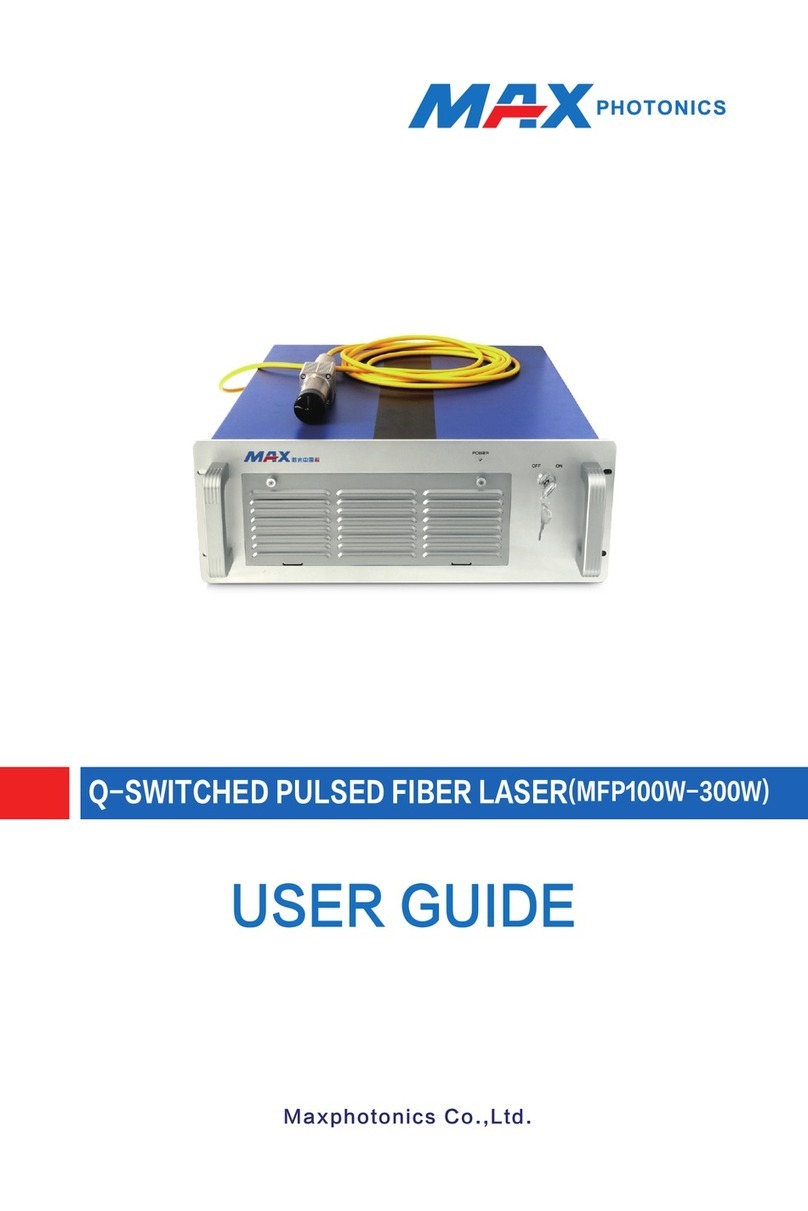
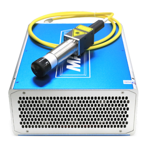
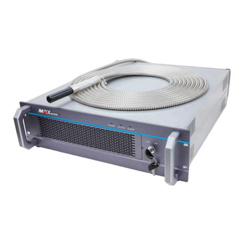
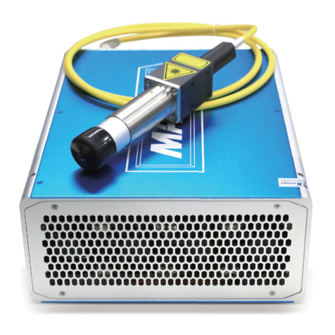
MAXPhotonics MFP-20 User manual

MAXPHOTONICS CO.,LTD
WWW.MAXPHOTONICS.COM
MFP-20
Pulsed Fiber Laser
User Manual

MAXPHOTONICS CO.,LTD
WWW.MAXPHOTONICS.COM 2
Please take time to read and understand this User’s Guide and
familiarize yourself with the information that we have compiled for
you before you use the product. This User’s Guide should stay with
the product to provide you and all future users and owners of the
product with important operating, safety and other information.
The MAXPHOTONICS Laser Model MFP-20 is a Class IV laser
product. Before turn on the power of 220VAC please make sure that
the interface is exact, otherwise, the laser model will be shattered.
This laser emits more than 20 Watts of invisible laser radiation in the
optical band near 1064 nm.
Avoid eye or skin exposure to direct or scattered radiation emitted
from the optical output.
Do not open the device. There are no user serviceable parts,
equipment or assemblies associated with this product. All service
and maintenance will be performed only at the factory.
Do not looking the optical output directly through eyes, please make
sure to wearing the laser safety glasses when operation.

MAXPHOTONICS CO.,LTD
WWW.MAXPHOTONICS.COM 3
Safety Information
Safety Conventions
This symbol indicates laser radiation. We place this symbol on products
which have a laser output.

MAXPHOTONICS CO.,LTD
WWW.MAXPHOTONICS.COM 4
Table of Contents
1. Description
1.1 Products Description……………………………………………………….5
1.2 Accessories………………………………………………………………...6
1.3 Environment and Precautions…………………………………………....6
1.4 Specification…………………………………………………………….....7
2. Installation
2.1 Installation Measurement Picture………………………………………...9
2.2 Installation Method ……………………………………………………….10
3. External Layout
3.1 Interface Specification………………………………………………. .11
4. Operation
4.1 Preparation for Use……………………………………………………..15
4.2 Operation Steps……………………….………………………………..16
4.3 Warning…………………………………………………………………..17
5. Quality Assurance,Warranty and Return Process
5.1 General Warranty…………………………………………………… 18
5.2 Warranty limitation……………………………………………………. 18
5.3 Service and Repairs…………………………………………………….18
6 RMA Clearance Form .

MAXPHOTONICS CO.,LTD
WWW.MAXPHOTONICS.COM 5
1. Description
1.1 Description
MFP-20 pulsed Ytterbium fiber laser is the one of most advanced products of
MAXPHOTONICS. It is a revolutionary, new, high-performance OEM device which
was developed for integration into high-speed, high resolution laser marking systems.
The main advantage of the MFP-20 offers over ten times improvement in per-Watt
optical power efficiency as well as low power consumption and practical robust design
over traditional diode-pumped solid-state lasers, and is suitable for either laboratory or
field operation. The source has a compact, rugged, stand-alone, ready-to-use, turn-
key design and can be directly integrated into user’s apparatus.
The laser emits periodical pulse train at 1064 nm wavelength and peak power up to 20
KW. Pulse repetition rate can be controlled either via separate remote control unit or
by external PC. The laser requires an 24V external DC power supply.

MAXPHOTONICS CO.,LTD
WWW.MAXPHOTONICS.COM 6
1.2 Accessories
Please check the included accessories according to Table 1.
Tab. 1
Items Quantity Note
Instruction
manual
1
1.3 Environment and Precautions
Power supply voltage for MFP-20 is 24±1 V DC.
WARNING: Always use your laser device in conjunction with properly
grounded power source.
CAUTION: Before supplying the power to the instrument, make sure that the
correct voltage of the DC power source is used (24 V). Failure to
use the correct voltage could cause damage to the instrument.
WARNING: No operator serviceable parts inside. Refer all servicing to
qualified MAXPHOTONICS personnel. To prevent electrical
shock, do not remove covers. Any tampering with the product will
void the warranty.
WARNING: This device has output optical head connected to the MFP-20 by
fiber cable. So please, be careful dealing with output head. Do not
separate the fiber and the laser head.
WARNING: If this instrument is used in a manner not specified in this
document, the protection provided by the instrument may be
impaired. This product must be used only in normal conditions.
WARNING: Do not install collimator when laser is active.

MAXPHOTONICS CO.,LTD
WWW.MAXPHOTONICS.COM 7
WARNING: MFP-20 Fiber Laser Module has three fans at the rear panel for
active cooling. Make sure that there is sufficient airflow to cool the
device.
WARNING: NEVER look directly into output head and make sure that you
wear appropriate laser safety glasses at all times while operating
the product.
WARNING: When you marking on the copper material, please do not to make
the marking area in the central ,or it will be damaged the laser.
WARNING: Power supply interruption is very dangerous for the equipment,
please provide continuous uninterrupted power supply voltage
CAUTION: In addition to the manual of controls or adjustments or
performance, other operations may cause the risk of radiation
exposure
CAUTION: It’s essential to keep the output lens cleaning. After use, please re-
covered the collimator.. Do not touch the output lens,. Please use
the lens tissue to clean it and do not use any solvents to clean.
CAUTION: Please follow the above guides to process, if not, it will cause
damage to the optics components, which should be excluded in
the warranty range.
1.4 Specification
OPTICAL CHARACTERISTICS
Mode of Operation Pulsed
Output Beam Mode M2 < 1.8
Polarization Random
Central Emission Wavelength, nm 1064 +/- 2
Nominal Average Output Power, W 20
Output Power Tunability, W 0 to 20
Long-Term Average Output Power Instability (over 5
hours), % < 5
Pulse Duration at 20 kHz, ns 70--120

MAXPHOTONICS CO.,LTD
WWW.MAXPHOTONICS.COM 8
Pulse Repetition Rate, kHz 22—70
Nominal Peak Power (pulse energy/FWHM pulse
duration), kW > 5
Peak Power Instability, % < 5
Residual Pump Power at the Output, dB <-60
OPTICAL OUTPUT
Output Fiber, m 20 / 125 / 3000/7000
Output Fiber Length, m 1.9/2.5/3
Output Collimator Bulk Lens
Output Beam Diameter ( 1/e
2
), mm 6-9
PUMP DIODES
Emission Wavelength, nm 970 +/- 10
Stripe, m 1x100
MTTF ( 20 C ), hours > 30 000
ELECTRICAL CHARACTERISTICS
Supplied Voltage, V DC 24
Nominal Total Current ( at 24 V, 20 C ), A < 8,5
Maximum Total Current, A < 15
Typical Power Consumption ( at 20 C ), W < 140
GENERAL CHARACTERISTICS
Operating Temperature Range, C 0 to (+40)
Storage Temperature, C (-10) to (+60)
Cooling Method 4 fans
Warm-up Time, s : 10

MAXPHOTONICS CO.,LTD
WWW.MAXPHOTONICS.COM 9
Humidity, % 10 to 95
Weight, kg 10
2.Installation
2.1 Installation Measurement Picture
2.1.1

MAXPHOTONICS CO.,LTD
WWW.MAXPHOTONICS.COM 10
2.1.2
Isolator Measurement
2.2 Installation Method
1).Connected the electrical mold and optics mold.That means connecting the cable
and radio cable (If the single radio cable) to the two ends of the molds separately.
2).Check that the AC voltage selector (24) set to the correct voltage, then plug the
remote control unit into the mains supply.
3). Install the external DC power supply (24 V) and connect the laser module DC
power

MAXPHOTONICS CO.,LTD
WWW.MAXPHOTONICS.COM 11
3. External Layout
3.1 25 pin D-shape connector pin assignment

MAXPHOTONICS CO.,LTD
WWW.MAXPHOTONICS.COM 12
Control Interface Operation as followings
1.This laser is controlled by connecting through the DB25 interface, the detail
information please view above sheet
2. Pin1~8 are the main line of setting the power of 8 bit,Pin1 is LSB,Pin8 is MSB。
The input range of this Pin is 0~255,and with 0~100% standard power data.
e.g.: please see as following sheet
Setup1 Setup 2 Setup 3 Setup 4 Setup 5
Pin1 0 0 0 0 1
Pin2 0 0 0 0 1
Pin3 0 0 0 0 1
Pin4 0 0 0 0 1
Pin5 0 0 0 1 1
Pin6 0 0 1 1 1
Pin7 0 1 1 1 1
Pin8 1 1 1 1 1
Current 50% 75% 87.5% 93.75% 100%
The power of
the laser
35% 65% 85% 92% 100%
4. Pin16 and Pin21 are for warning, the 2 Pin show the situation as followings.
5. Pin18 is the switch sign of MO(main surge).MO should be turn on before 4ms when
open the Booster(BS).After turning on the MO ,the laser will have some electricity
consumption.
Notes:MO and Pin18 should be turning on at the same time.
6. Pin19 is the input end of launching controller Booster(BS).when level is H, please
turn on the BS,when level is L, please turn off BS, when the Pin19 change to lever

MAXPHOTONICS CO.,LTD
WWW.MAXPHOTONICS.COM 13
H, the laser will be out after stated delay. When the level is L, the laser will be turned
off after stated delay.
Notes:
a. MO should be turned on before 4ms of BS, if not, it will be no laser output.
b. If turning on the BS first, then the MO,the laser will be out after 1~4ms. The
above two situation is not list in the manual as they are unusual operation, please try
to avoid them. BS should be turned on together with the data rising.
7. Pin20 is the input interface of in-phase,The pulse of laser output should be the same
steps with signal rising at the stated range ,the pulse repetition rate from this side to input
(PRR)(referring the limitation of PRR).
Notes:if the input PRR above the stated range, the protection system of laser will
protect the loop and recruit the loss pulse or limitation the data of PRR.
8. Pin23 is the input interface of “emergency stop”. When running ok, the level should
be H, once the level change to L, the laser will be stopped automatically(the same with
MO&BS)which isn’t depend on the other control signal. When restart the laser, please
make sure that the level of MO &BS should be down to L (if the original is H).If need
the laser running normally, this signal should be at H level 2μs earlier before offering the
MO&BS.
Laser Running
1.Please take off the protecting covering from the laser output head.
2.Please connected the laser mold and control system through DB-25 interface, please
make reference from the leading of DB25 if necessary
3.Please make sure that the following interface at the initialization rightly
a) Pin18,19,22,23 at level L ;
b) The Repetition frequency of Pin20 at the stated range
4. Connected the 24VDC power and laser power line(+24V to brown,ground to
green/yellow,- to blue)
5. Laser will be running after 120s when gaining the 24VDC power(warming-up time).
Notes:it’s allowing to offer the 24VDC main power first,then make the control
signal initial
6. Make the emergency stop to(Pin23)H。
7. Set up the required power through Pin1~8.

MAXPHOTONICS CO.,LTD
WWW.MAXPHOTONICS.COM 14
8. Set up the Pin18 to and turning on MO.
9. Waiting about 4ms.
10. Through Pin19 to modulate the laser. Input H/L to control the laser’s switch. The
up and down time have been limited(referring the specification)The modulate
speed can not be faster than the total value of up and down’s time. The typical time
should be 250us,the period of modulate should be above 500us(the related
frequency should be 2kHz).
11. After finished a turning on/off operation, and wait for the next task, if the time above
20ms,please turn off the MO,and it can decrease the power consumption, extend the
using life of MO, and avoid the balance power output of MO.
12. When finished a task, please turn off the BS &MO(Pin18 & Pin19 should be L ).
13. Cut down the power of 24VDC .
Power Connected
The laser power line as followings
CATHODE PE
A
NODE

MAXPHOTONICS CO.,LTD
WWW.MAXPHOTONICS.COM 15
2.
4. Operation
4.1 Preparing for use
4.1.1 Checking the fiber laser power, marking system power and computer connected
finished
1.1.2 Checking the signal of marking system and fiber laser power.
MAXPHOTONICS CO.,LTD certifies that this instrument has been thoroughly tested
and inspected, and found to meet published specifications prior to shipping.
NOTE: Upon Receiving your device check the packaging and parts for any possible
damage that may have occurred in transit. If damage is apparent please contact
MAXPHOTONICS CO.,LTD immediately.
4.2 Operation Steps
4.2.1 Operation Steps
Turn on the fiber laser power, then the marking system power(make sure that the fiber
laser power on and the fan running within the 180s warm-up time of the marking
system ),otherwise, should return-on according the order and turn on the computer
power at the end.
4.2.2 Operation steps of checking laser marking system after turning on
When start to test the fiber laser after start-up finished, please set up the power to
0W,then make a picture, marking continually and add the power from 0W to 20W.
And also to test by using a camera paper, and notice that the laser must be getting
stronger( the step should be taken when starting the machine each time, please turn
off the machine to check when the laser does not become stronger or there isn’t any
laser. After the work in order, marking can be started following the normal procedure.
4.3 Warning
4.3.1 The highest frequency should be70KHz
4.3.2 Please be careful when you adjust the rate of frequency when marking, or it will
influence the marking results.
4.3.3 It’s workable for MAXPHOTONICS fiber laser to turn off the laser power directly

MAXPHOTONICS CO.,LTD
WWW.MAXPHOTONICS.COM 16
5. Quality Assurance, Warranty and Return Process
5.1 General Warranty
The warranty of Maxphotonics fiber laser is 24 months upon the customer receive the
fiber laser .
All products are warranted by MAXPHOTONICS against defects in materials and
workmanship for the period of time as set forth on the applicable purchase order or in
the specifications starting with the date of shipment. MAXPHOTONICS also warrants
that this product will meet applicable specifications under normal use.
MAXPHOTONICS shall, at its option, repair or replace any product that proves, in the
reasonable opinion of MAXPHOTONICS, to be defective in materials or workmanship
during the warranty period. All products repaired or replaced under warranty are only
warranted for the remaining un-expired period of time in the original warranty for the
particular defective product. MAXPHOTONICS reserves the right to issue a credit note
for any defective products that have proved defective through normal usage.
5.2 Warranty Limitations
This warranty excludes products, parts (including fiber connectors) or equipment
which have been tampered with, opened, disassembled, opened, or modified by
persons other than MAXPHOTONICS personnel, misused, neglected, or damaged by
accident, used in applications which exceeds their specifications or ratings, used
outside of environmental specifications for the product, used with buyer software or
interfacing, improperly installed, maintained or otherwise abused or used other than in
accordance with the information and precautions contained in this User’s Manual. It
is the customer’s responsibility to understand and follow operating instructions in this
User’s Guide and specifications prior to operation—failure to do so may result in
voiding this warranty. Accessories and fiber connectors are not covered by this
warranty.
Buyer must claim under the warranty in writing no later than 31 days after the claimed
defect is discovered. This warranty does not extend to any third party, including
without limitation Buyer's end-users or customers, and does not apply to any parts,
equipment or other products not manufactured by MAXPHOTONICS.

MAXPHOTONICS CO.,LTD
WWW.MAXPHOTONICS.COM 17
5.3 Services and Repairs
CAUTION:No operator serviceable parts inside. Refer all servicing to qualified
MAXPHOTONICS personnel. All requests for repair or replacement under this
warranty must be made as soon as possible after the defect has been noticed and
must be directed to MAXPHOTONICS Fiber Laser or its representative in your area.
Items authorized for return by us must be returned in a suitable container.
Any damage noted upon receipt of the unit must be documented for appropriate claim
against the carrier.
Changes
We reserve the right to make changes in design or constructions of any of our
products at any time without incurring any obligation to make changes or install the
same on units previously purchased.

MAXPHOTONICS CO.,LTD
WWW.MAXPHOTONICS.COM 18
6. RMA Clearance Form
RMA File No. (req’d)
(given by MX.):
Total Number of
Unit(s) Returned:
Serial No(s): 1.
___________ 2.
_____________ 3.
___________
Please ship the unit(s) to:
MAXPHOTONICS CO.,LTD
Mingschin Industrial Park,Nanhuan Road ,Shajing Town,Bao’an,Shenzhen,China
Attention: Quality Manager
This RMA file number will expire 31 days after the faxed date from MAXPHOTONICS FIBER LASER.
Thereafter, units received in under the expired RMA number will result in a longer turn around time.
Please include one COPY of this form signed by the MAXPHOTONICS Fiber Laser Quality Manger with
the return of your unit(s).
INSTRUCTIONS FOR PRODUCT RETURNS
1. MAXPHOTONICS Fiber Laser will only accept returns for which an
approved Return Material Authorization (RMA) has been issued by
MAXPHOTONICS Fiber Laser. You must first call the Quality Manager
of MAXPHOTONICS CO.,LTD at +86-4006638119 to discuss the return
and request a RMA number. You must return defective products freight
prepaid and insured to MAXPHOTONICS FIBER Laser at the address
shown herein. All products which have returned to MAXPHOTONICS Fiber
Laser but which are found to meet all previously applicable specifications for
such products or which indicate damage to the fiber connectors not resulting
from defect manufacturing, shall be subject to MAXPHOTONICS Fiber
Laser’ standard examination charge in effect at the time and these costs
shall be charged to the Buyer. All products returned to MAXPHOTONICS
FIBER Laser which are not accompanied by an itemized statement of
defects, shall be returned to the Buyer at the Buyer’s expense and
MAXPHOTONICS Fiber Laser shall not carry out any evaluation of such
products. MAXPHOTONICS Fiber Laser warrants to Buyer that its services,
labor and replacement parts, assemblies and modules will be free of defects
in material and workmanship for ninety (90) days from the date of shipment
or performance of services.
2. Warranty Returns - Domestic & *International Buyers should pay for one-
way freight costs to MAXPHOTONICS CO.,LTD. MAXPHOTONICS Fiber
Laser will reimburse Buyers for applicable reasonable third-party freight
costs and MAXPHOTONICS Fiber Laser will pay for freight return cost back
to the Buyer.

MAXPHOTONICS CO.,LTD
WWW.MAXPHOTONICS.COM 19
3. Non-Warranty Returns - Domestic & *International Buyers are responsible
for two-way freight costs. If shipment consists of returns that are both
warranty and non-warranty, the shipment will be considered as non-warranty.
Any UNAUTHORIZED shipments billed to MAXPHOTONICS Fiber Laser
without authorization will be re-invoiced to the Buyer. Confirming purchase
orders are required for non-warranty returns.
4. *International Returns must include applicable DUTIES AND TAXES, and
you must mark air bills with “RETURNED FOR REPAIR”. In any event,
where MAXPHOTONICS Fiber Laser accepts a shipment, MAXPHOTONICS
Fiber Laser will invoice to the Buyer for any charges as stated above.
5. Returns for credit will not be accepted unless authorized in advance, in
writing by MAXPHOTONICS Fiber Laser, in accordance with
MAXPHOTONICS Fiber Laser’ Terms and Condition, including the warranty
provisions. In most cases, restocking fees will apply.
6. All returns must be packaged adequately to avoid damage during shipment.
7. Complete packing list with product model and serial number will insure
prompt repair, if the other terms of this form are followed.
8. See the MAXPHOTONICS Terms and Conditions for the applicable warranty
for the products before you request the return of the products.
_________________________________
MAXPHOTONICS CO.,LTD
Quality Manager Signature (required)
__________________
Date
Table of contents
Other MAXPhotonics Measuring Instrument manuals
Popular Measuring Instrument manuals by other brands

Ditel
Ditel Kosmos series instruction manual

Wentronic
Wentronic 52485 Installation and user manual

DeFelsko
DeFelsko PosiTector UTG quick start guide

Compressed Air Alliance
Compressed Air Alliance POM200 user manual

Jadak
Jadak PHOTO RESEARCH CINEBRATE PR-653 user manual

Sony
Sony DK110NLR5 instruction manual