Sonel MRU-200 User manual

Enabling auto-zeroing
Disabling auto-zeroing
Sonel MRU-200 / 200-GPS
Earth Resistance Meter ●QuickStart
v1.01 | 20.05.2020
Wire continuity measurement
Connect the meter to the measured wire.
Run the measurement using START button.
Current measurement
Connect the meter to the measured object using clamp.
Using START button run the measurement.
2P
F1 select the type of clamp
In order to eliminate the inuence of the resistance of the test leads
over the result of the measurement, its compensation (auto-zeroing)
has to be done.
Press START.
Using button F1 enable AUTOZERO mode.
Short-circuit the test leads.
Press START.
Using button F1 enable AUTOZERO mode.
Separate the test leads.
It is sufcient to realize compensation once for the given test leads.
It is also remembered once the meter has been turned off, until the
next successful auto-reset procedure.
I
First steps
Turn on the meter
Select the method and connect
Congure
Obtain the result
Measurements
The meter is designed for measurements at interference voltages which do not exceed 24 V
for REmeasurements and 3 V for RCONT measurements. The voltage is measured up to 100 V,
but above 40 V is indicated as dangerous. The meter must not be connected to voltages ex-
ceeding 100 V.
UN>24V!
The voltage on the mea-
surement points exceeds
24 V but is lower than
40 V. The measurement
is blocked.
NOISE!
The value of the interfering
signal is too high. The result
may be distorted by additional
uncertainty.
LIMIT!
The uncertainty of the
electrode resistance
>30%. Uncertainties
calculated on the basis of
the measured values.
UN>40V!
and a contin-
uous
sonic signal
The voltage on the
measurement points
exceeds 40 V. The mea-
surement is blocked.
R>19,99kΩ
RE>19,99kΩ
RS>19,9kΩ
RH>19,9kΩ
ρ>999kΩm
Measurement range
exceeded. IL>max
Excessive interfering
current, the measurement
error may exceed the
basic error.
In MRU-200-
GPS you can
enable GPS.
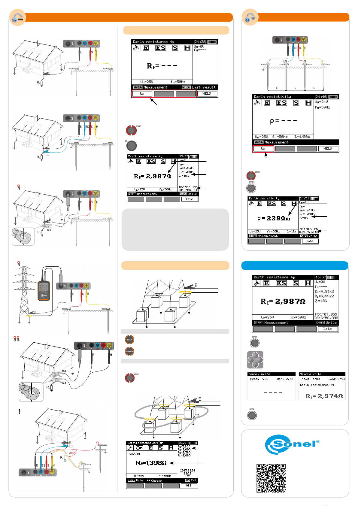
Main result
Measure-
ment date
GPS co-
ordinates
MRU-200 / MRU-200-GPS
ERP-1
Saving a result to the memory
After the measurement press ENTER.
Select memory cell using buttons ▲▼.
Select memory bank using buttons ◄►.
Connect the meter to the leg of the measured pole.
Using START button run the measurement.
Wrap the clamps around next legs according to instruc-
tions on the display. Keep one direction of connecting
to pole legs (clockwise or counter-clockwise).
Earth resistivity measurement
Connect the meter to the measured earth.
Enter settings
▪F1 measuring voltage
Using button ENTER run the measurement.
Press START.
Using buttons ▲▼enter the distance between electrodes.
Press F2 and select ERP-1 adapter.
Earth resistance measurement RE
3P
3P
3P
4P
4P
Measurement of RE of poles using ERP-1 adapter
Target cell empty Target cell occupied
Press ENTER to save the result.
Find more information
in the user manual
and on our website
www.sonel.com
Enter settings
▪ F1 voltage/pulse shape
▪ F2 selection of C-3/ERP-1 (3P+clamp method)
▪ F3 selection of the number of pole legs (ERP-1)
Using button START run the measurement.
Conguration and RE measurement
Using button F4 display coordinates of the measured point.
UN........voltage on the measurement points
fN..........interference frequency
IL..........interfering current
RH........resistance of current electrode
RS.........resistance of voltage electrode
δ..........additional uncertainty caused by the resistance of the electrodes
R1...R4..earth resistance of the pole leg no. 1...4
Main result
Additional
results
GPS co-
ordinates
Using FLEX button select the type of exible clamps
connected to the device.
Using TURNS button select the number of exible
clamp wraps around the pole leg.
Resistance of
individual
pole legs
Resultant
resistance
Main result
Additional
results
GPS co-
ordinates
Other manuals for MRU-200
2
This manual suits for next models
1
Other Sonel Measuring Instrument manuals

Sonel
Sonel MPI-506 User manual

Sonel
Sonel MPI-505 User manual

Sonel
Sonel KT-128 User manual

Sonel
Sonel MIC-10k1 User manual

Sonel
Sonel LKZ-710 User manual

Sonel
Sonel CMP-3000 User manual

Sonel
Sonel LMW-100 User manual

Sonel
Sonel MRU-30 User manual

Sonel
Sonel LXP-10B User manual

Sonel
Sonel MRU-120HD User manual

Sonel
Sonel MPI-540 User manual

Sonel
Sonel MIC-30 User manual

Sonel
Sonel PQM-707 User manual

Sonel
Sonel PQM-702 User manual

Sonel
Sonel MIC-2511 User manual

Sonel
Sonel MMR-640 User manual

Sonel
Sonel MPI-520 User manual

Sonel
Sonel MRU-21 User manual

Sonel
Sonel CMP-1006 User manual

Sonel
Sonel KT-400F User manual


