ASA Electronics iN-Command NCSP3 Owner's manual

RV CONTROL AND MONITORING SYSTEM
Patent # (D776,068)
Patent # (D762,644)
Patent # US 9,679,735
™
™
NCSP3
Installation and Operation Manual


NCSP3
Read the iN-Command Manual, and these warnings and instructions carefully before using this product. Failure to follow the use
instructions in this owner’s manual, or improper use of the Mobile Application, Display Commander and/or Body Control Module, could
result in personal injury, including death.
Do not operate while vehicle is being driven. The Mobile Application, Display Commander and/or Body Control Module should not be
used while the vehicle is being driven. Use of the Mobile Application, Display Commander and/or Body Control Module while the vehicle
is being driven is dangerous and may cause personal injury or property damage.
For adult use only. The Mobile Application, Display Commander and Body Control Module are intended for adult use only, and are not
to be used by persons under the age of 18. Use by children may cause personal injury or property damage.
Operate only when you have a clear line of sight. Do not operate any moving parts (including, but not limited to, awnings, jacks and
slides), unless you have a clear line of sight to the moving part. The Mobile Application, Display Commander or Body Control Module
may be used only if you are giving instructions to, and receiving instructions from, another person at least age 18 or older who can clearly
see the moving part. Failure to follow these instructions may result in serious personal injury or property damage.
Do not operate under the inuence of alcohol or drugs. Do not operate the Mobile Application, Display Commander or Body Control
Module while under the inuence of alcohol or drugs. Doing so may result in personal injury or property damage.
Avoid moisture. To reduce the risk of re or electric shock, do not expose this equipment to rain or moisture.
Use recommended accessories. To reduce the risk of re or electric shock and annoying interference, use only the recommended
accessories.
Important Safety Information

NCSP3
3
TABLE OF CONTENTS ...........................................................3
INTRODUCTION .....................................................................4
Thank You! .............................................................................4
Features.................................................................................4
Precautions ............................................................................4
Packing List............................................................................4
INSTALLATION ........................................................................5
Tools and Supplies .................................................................5
Disconnecting the battery.......................................................5
Selecting the Mounting Location............................................5
Mounting the Display Commander (DC) ................................5
WIRING ...................................................................................6
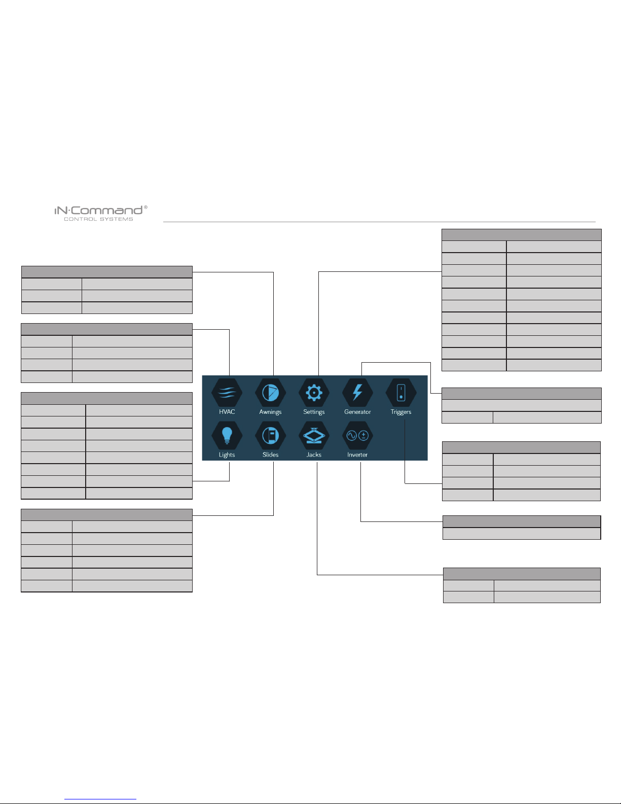
SETUP MENU LIST .................................................................7
TRAVEL LOCKOUT (Safety) ...................................................8
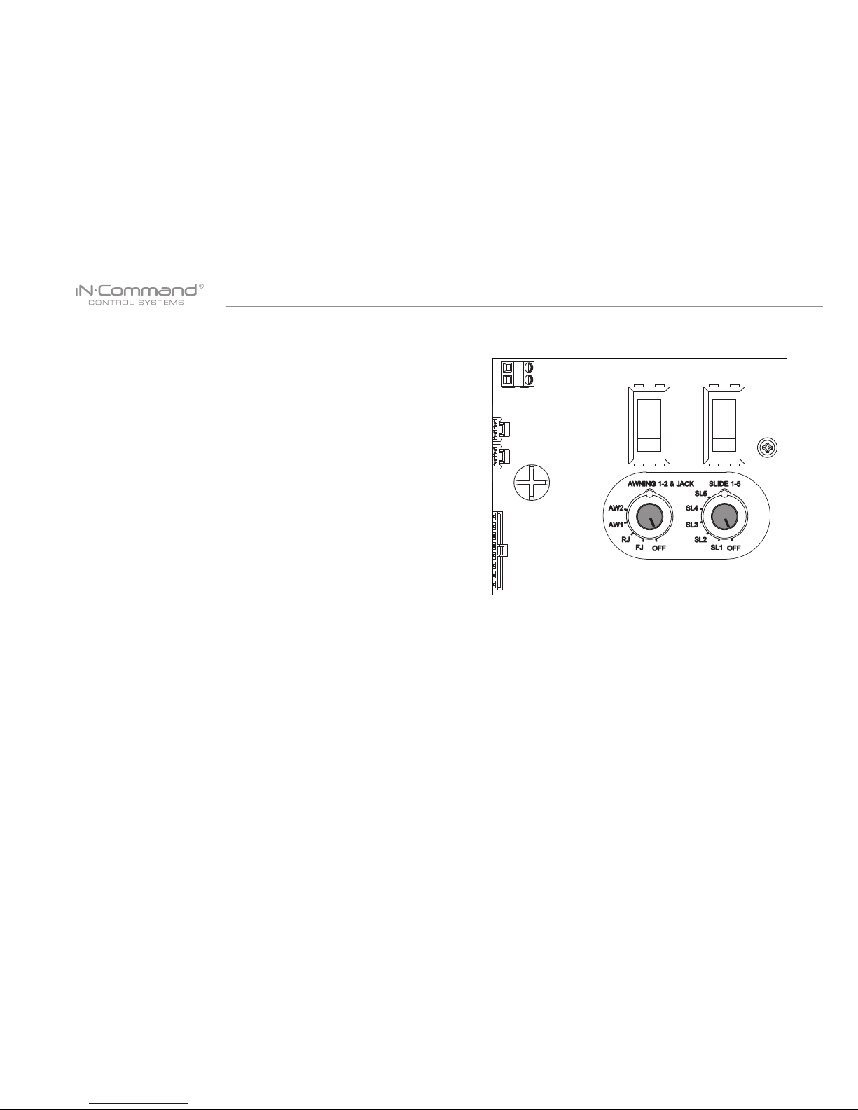
OVERRIDE SWITCHES* ............................................ 9
SPECIFICATIONS .................................................................10
FCC Notes ...........................................................................10
PASSCODE PROTECTION .................................................. 11
SETTINGS ............................................................................. 11
Text Editing........................................................................... 11
Scroll List Editing* ................................................................13
Triggers ...............................................................................14
Generator Fuel ....................................................................14
Alarm Inputs.........................................................................14
Passcode .............................................................................14
Set Passcode Timer ..........................................................15
Change Passcode .............................................................16
Clear Passcode .................................................................16
MOBILE DEVICES: ...............................................................17
Pairing Mobile Device to DC ................................................18
CHECKING ACTIVE BLUETOOTH SESSION ......................22
HVAC ............................................................................................................ 23
Vent Fans ................................................................................................. 23
Fan Only Mode ......................................................................................... 23
AC Cooling ............................................................................................... 23
Heating ..................................................................................................... 24
Auto .......................................................................................................... 24
HVAC Schedule........................................................................................ 25
AUTO GENERATOR START ........................................................................ 25
Generator Schedule ................................................................................. 26
Date & Time.............................................................................................. 27
SOFTWARE UPDATE* ................................................................................. 28
RESET: FLOOR PLAN ................................................................................. 31
TOUCH SCREEN CALIBRATION ................................................................ 32
SYSTEM CALIBRATION* ............................................................................. 33
TROUBLE SHOOTING ................................................................................. 35
• TABLE OF CONTENTS

NCSP3
4
• INTRODUCTION
• Thank You!
Thank you for choosing a iN-Command product. We hope you will nd
the instructions in this owner’s manual clear and easy to follow. If you
take a few minutes to look through it, you’ll learn how to use all the fea-
tures of your new iN-Command system for maximum enjoyment.
• Features
Features of iN-Command system include:
• Simultaneous control by up to three Android Devices and
one iOS Device
• Control four zones of Interior Lighting
• Control three zones of Exterior Lighting
• Monitor all water and fuel tank levels
• Control and monitor the Water Heater
(switches between LP, AC, or both)
• Control and monitor the Water Pump
• Control and monitor the Generator (including all faults)
• Control Awnings & Awning Lights
• Control Electric and Hydraulic Slides
• Control Jacks (non-automatic function)
• 4 Programmable Auxiliary 12V Triggers
• 4 Alarm Inputs (12V)
• Monitor Battery Voltage with Low Voltage Alert
• Auto Generator Start
• Precautions
• Use the Proper Power Supply.
This product is designed to operate with a 12 volt DC, negative
ground battery system (the standard system in a North American
vehicle).
• Use Authorized Service Centers.
Do not attempt to disassemble or adjust this precision product;
contact a professional for assistance.
• Avoid Moisture.
To reduce the risk of re or electric shock, do not expose this
equipment to rain or moisture.
•
•
(1) Cover, (2) Thumb Screws (1) Body Control Module (BCM)
(1) Display Commander (DC)
• Packing List
• Avoid Cleaning Products.
The front of this unit should only be cleaned with a slightly damp cloth.
Do not use cleaning products.
• Use Recommended Accessories.
TO REDUCE THE RISK OF FIRE OR ELECTRIC SHOCK AND
ANNOYING INTERFERENCE, USE ONLY THE RECOMMENDED
ACCESSORIES.

NCSP3
5
• INSTALLATION
It’s a good idea to read all of the instructions before beginning
the installation.
• Tools and Supplies
You will need these tools and supplies to install your iN-Command:
• Phillips screwdriver
• #2 square drive bit
• Wire cutters and strippers
• Electrical tape
• Volt meter/test light
• Crimping tool
• Fork Crimp connectors
• Minimum of 24 gauge wire required to connect DC to BCM
• 10 gauge wire for power and slide connections
• 14 and 18 gauge wire for all other connections
• Four #8 PH (0.164” x 0.75”) screws for the DC
• Six #8 PH (0.164” x 1.0”) screws for the BCM
• Disconnecting the battery
To prevent a short circuit, be sure to turn off 12V power and
remove the negative (-) battery cable prior to installation.
• Selecting the Mounting Location
Select a mounting location, taking care to avoid the following:
• Places exposed to heat-radiating appliances such as
electric heaters
• Adjacent to other equipment that radiates heat
• Poorly-ventilated or dusty places
• Moist or humid locations
CUTOUT FOR DISPLAY COMMANDER (DC)
NOTE: Before cutting the mounting hole, make sure the area
behind the mounting location is clear of wires, fuel and vacuum
or water lines; ensure there is at least a 2.75”clearance below
the Display Commander to allow for programming by USB stick.
RECOMMENDED CUTOUT
WALL FOR
REFERENCE
CUTOUT 4.33"
6.63"
• Mounting the Display Commander (DC)
• Use the mounting hole diagram to measure and cut a mounting
hole, allowing space below for future programming via USB drive
• Route power wires through the hole and connect
• Check and ensure correct operation
• Mount the unit using four #8 PH (0.164” x 0.75”) screws
• Attach Trim ring

NCSP3
6
• WIRING
The wiring diagram depicts all the wiring connections required for proper operation of the unit.
BODY CONTROL MODULE (BCM) CONNECTIONS

NCSP3
7
• SETUP MENU LIST
Tiggers
Trigger 1 No, Momentary , Latch
Trigger 2 No, Momentary , Latch
Trigger 3 No, Momentary , Latch
Trigger 4 No, Momentary , Latch
Jacks
Front Up, Down
Rear Up, Down
Generator
Prime, Start, Manual
Schedule Start time, Stop time
Inverter
HVAC (Zone1, Zone2, Zone3)
Mode On, Off, Fan, Cool, Heat, Auto
Vent Open, Shut
Vent Fan Off, Low, Medium, High
Schedule Start time, Stop time
Awings
Awning Light No, Yes
Awning 1 In, Out
Awning 2 In, Out
Slides
Hydraulic In, Out
Slide 1 In, Out
Slide 2 In, Out
Slide 3 In, Out
Slide 4 In, Out
Slide 5 In, Out
Lights
Light Group 1 No, Yes
Light Group 2 No, Yes
Light Group 3 No, Yes
Light Group 4 No, Yes
Awing Light No, Yes
Dimmer Light 1 No, Yes
Dimmer Light 2 No, Yes
Dimmer Light 3 No, Yes
Settings
Bluetooth Scan
Wi-Fi On, Off, Scan, Add
Date & time Edit
Edit
Passcode Setting
Brightness Up, Down
Calibration Set
System Reset Floor Plan , Factory
Information Information notes
Software DC/App/BCM Updat
Administration

NCSP3
8
• TRAVEL LOCKOUT (Safety)
iN-Command is equipped with a Travel Lockout feature to ensure
certain system functions are unavailable during transit.
When the Brake Signal on the tow vehicle is activated, the iN-
Command will lock down all motorized functions. The Display
Commander (DC) and mobile devices will also display “Travel Lock
Engaged” and the affected buttons will cease to activate.
The lights, water pump, water heater, generator and tanks sensors
will continue to function.
To turn the Travel Lock off, press "Disengage" on the Display
Commander (DC), inside the RV, once the brake signal has been
removed.

NCSP3
9
• OVERRIDE SWITCHES*
The Body Control Module has a bank of override switches.
The rotary switches below each rocker switch correspond to an
electric function* made by the Display Commander.
The left switch controls the awning and jacks.
The right switch controls the slides.
To use the override switches, locate the switch needed to actuate
the desired component. Rotate the switch underneath the rocker
switch to select the motor. Press up or down on the switch.
The switch is momentary and will activate the motor only while
pressed in either direction.
* The hydraulic overrides are located on the hydraulic
pump; consult the hydraulic pump owner’s manual for
more information.

NCSP3
10
• SPECIFICATIONS
Display Commander (DC)
Operating Voltage . . . . . . . . . . . . . . . . . . . . . . . . . . . . . . 12VDC
Maximum Current Draw . . . . . . . . . . . . . . . . . . . . . 1.5A@9VDC
Minimum Operating Voltage . . . . . . . . . . . . . . .. . . . . . . . 9VDC
Maximum Operating Voltage . . . . . . . . . . . . . . . . . . . . . 16VDC
Body Control Module (BCM)
Operating Voltage . . . . . . . . . . . . . . . . . . . . . . . . . . . . . . 12VDC
Maximum Current Draw . . . . . . . . . . . . . . . . . . . . 8.5A@12VDC
Minimum Operating Voltage . . . . . . . . . . . . . . . . . . . . . . 9VDC
Maximum Operating Voltage . . . . . . . . . . . . . . . . . . . . . 16VDC
NCSP3 System
EPROM Non-Volatile Memory . . . . . . . . . . . . . . . . . . . . . . YES
Bluetooth Version . . . . . . . . . .. . . . . . . . . . . . . . . . . . . . 4.0 BLE
General
Body Control Module . . . . . . . . 14.9” (W) x 17.9” (D) x 1.8” (H)
Display Commander . .. . . . . . . . . . 7.7” (W) x 5.2”(D) x 1.3” (H)
NOTICE 1:
The changes or modications not expressly approved by the party
responsible for compliance could void the user's authority to
operate the equipment.
NOTICE 2:
This equipment has been tested and found to comply with the limits
for a Class B digital device, pursuant to Part 15 of the FCC Rules.
These limits are designed to provide reasonable protection against
harmful interference in a residential installation.
IMPORTANT NOTE:
To comply with the FCC RF exposure compliance requirements,
the antenna(s) used for this transmitter must be installed to provide
a separation distance of at least 20 cm from all persons and must
not be co-located or operating in conjunction with any other
antenna or transmitter. No change to the antenna or the device is
permitted. Any change to the antenna or the device could result in
the device exceeding the RF exposure requirements and void
user’s authority to operate the device.
This equipment generates, uses and can radiate radio frequency energy
and, if not installed and used in accordance with the instructions, may
cause harmful interference to radio communications.
However, there is no guarantee that interference will not occur in a
particular installation. If this equipment does cause harmful interference
to radio or television reception, which can be determined by turning
the equipment off and on, the user is encouraged to try to correct the
interference by one or more of the following measures:
• Reorient or relocate the receiving antenna.
• Increase the separation between the equipment and receiver.
• Connect the equipment into an outlet on a circuit different from that to
which the receiver is connected.
• Consult the dealer or an experienced radio/TV technician for help.
• FCC Notes

NCSP3
11
• PASSCODE PROTECTION
Conrm the new passcode.
• Text Editing
• SETTINGS
1. Select “Settings”
From the Menu screen you can:
• Edit iN-Command function text
• Reposition functions
• Enable/disable functions
• Change the switch properties (from momentary to latch)
• See the status of iN-Command
• Connect devices with Bluetooth
• Change the passcode
• Reset the oor plan
• Control the brightness of the DC screen
• View IN-Command’s Legal documents and customer
support information.
The Setup button is used by the manufacturer.
A passcode is required to access the system.
On the rst time use of the system, the user is required to enter
and conrm a new passcode.

NCSP3
12
5. Use the keyboard to edit the name, then press "Save"
2. Press “Edit” to enter “Edit” page
3. Select the function to edit.
Note: Editing the text on the DC will not change the text on
a device’s App.
4. Long press the intended text, e.g., "Light Group 3"

NCSP3
13
3. Select the funcition to edit.
2. Press “Edit” to enter “Edit” page
• Scroll List Editing*
1. Select “Settings”.
4. Use the Up and Down arrows next to the function to move
the item in the list.

NCSP3
14
Triggers can be added to the system. “Momentary” or “Latch” can
be selected for each Trigger. Note: Desired devices need to be
correctly wired to the BCM to function.
• Triggers
In the Generator Page, Gasoline or Propane can be selected for
the fuel type.
• Generator Fuel
Alarm inputs can added to the system.
Note: Desired devices need to be correctly wired to the BCM to
function.
• Alarm Inputs
• Passcode
1. Select “Settings”.

NCSP3
15
2. Press “Passcode” to enter passcode setup.
2.1 Enter the correct passcode to proceed.
3. The passcode setup window will open.
•Set Passcode Timer
Press “Set Timer” select the idle time to activate the
passcode protection.
Clear Passcode

NCSP3
16
3. Conrm new passcode.
Press the “Clear Passcode” to clear the passcode.
This will restart the App, take the user to the End-User License
Agreement, and have the user setup a new passcode.
1. Press the “Change Passcode” button to change to a new
passcode.
2. Enter the new passcode.
•Change Passcode •Clear Passcode

NCSP3
17
• MOBILE DEVICES:
iN-Command is able to pair to Android and iOS devices using
the iN-Command App.
Visit the Google Play and Apple App stores on your mobile
device to check compatibility of your device.
Seven mobile devices are able to be paired to iN-Command at
one time, but only 1 iOS and 3 Android devices are able to be
actively paired; meaning, 3 Android devices and 1 iOS device
can all actively control the iN-Command functions.
To use another device not actively paired to iN-Command, 1
device needs to shut down its iN-Command App to allow another
device to actively pair. To do this simply select the power button
on the App or shut down the App in the device’s settings menu.

NCSP3
18
• Pairing Mobile Device to DC
1. Enable "Bluetooth" in the system settings of the mobile
device
2. From the DC Home page, select "Settings"
2.1 Select the "Bluetooth" tab.
2.2 Select "Pairing" to pair devices and view current paired devices.

NCSP3
19
2.3 Press Scan to start scanning for Unpaired devices.
Locate the mobile device in the Unpaired Device list.
Select the device by pressing it.
2.4 A Popup with the device name will apear on the display.
Pass "Pair"
2.5 A Bluetooth Pairing request will appear on the DC and
mobile device.
2.6 Press "Pair" on the DC.
2.7 Press "Pair" on the mobile device.
Table of contents
Other ASA Electronics Measuring Instrument manuals
Popular Measuring Instrument manuals by other brands

Ametek
Ametek WDG-V user manual

Kobold
Kobold DAH operating instructions

Vega
Vega VEGACAL 69 operating instructions

P3 International
P3 International P0320 Operation manual

Allendale Electronics
Allendale Electronics AE-MAN-DS user manual

Emerson
Emerson Rosemount 3410 Series Maintenance and troubleshooting manual