Mic 98850 User manual

OPERATION MANUAL
THERMOCOUPLE PEN
98850/98851/98852/98853/98855
Auto power off with disable feature(15 minutes).
Data hold function freezes readings on display.
°C / °F select function.
High / Low alarm threshold setting is available.
(98851/98853/98855)
K/J/T type selectable(98852/98853)
FEATURES
MATERIAL SUPPLIED
Operation manual
K type probe
Meter
CR2032 battery

KEYPAD (CONTROLS)
(1) PWR: Turn on / off the meter or data hold mode.
(2) MX/MI/AVG: MAX / MIN / AVG mode.
(3) MODE: Short press for temperature, REL, Air T.
(98851/98853 / 98855 only), RH (98855 only).
Long press for K, J, T mode (98852 / 98853
only).
DPHIWBGTHiLoSet
K
J
A
RH
MAX
RS REL
MIN
AVG
HOLD
BAT
%
Moist
E
T
T
K
OPERATION
(1) POWER ON / OFF
Make sure you have plugged in the thermocouple
probe before turn on the meter. Long press PWR
button to turn on the meter, the full screen of LCD will
quick show on the display, the meter now is in normal
measurement mode. While the meter is on, long press
PWR button to turn off the meter.
(2) SLEEP MODE (AUTO POWER OFF)
The meter will turn off automatically after 15 minutes if
no press action is taken. To disable auto power off
function, when the meter is off, long press MX/MI/AVG
button and press PWR button, the display of LCD will
show “5-no℃" , means auto power off function as below
has been turned off. After setting, the meter will turn on
automatically.
NOTE: Please make sure the probe type before select
this function to ensure get correct reading.

(4) DATA HOLD
Short press PWR button to freeze reading.
Short press PWR button again, the meter will return to
normal measurement.
Press MODE button to select REL, Air Temp.(98851/
98853&98855) and Relative humidity(98855 only)
(5) CHANGE MODE
HOLD
K
Press MODE
R H
%
Press MODE
Press MODE
K
A
T
REL
Press MODE
(98855 only)(98851&98853&98855)
Make sure you have plugged the K sensor probe in
meter, if the probe is not plugged in appropriately, the
LCD will show “----” on the display.
(3) TAKING MEASUREMENT
(6) SELECT PROBE TYPE
Long press MODE button more than 3 seconds to
select probe type K/J/T(98852&98853)
K
J
T
(98851&98852&98853&98855)
(9) ALARM SETTING(98851/98853/98855)
K
Hi
K
Hi
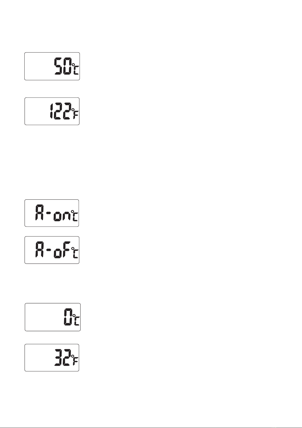
(8) CHANGE UNIT
Press MODE
When the power is off, press MODE and PWR button
to enter setting function. Press MODE button to select°C
or °F. Press PWR button again will save the unit. Enter
into alarm setting.
(7) MAX / MIN / AVG
Short press MX/MI/AVG button, MAX icon with the
highest reading(the digit from powered on) appears
on LCD. Press MX/MI/AVG button again, MIN icon with
the lowest reading (the digit from powered on) appears
on the LCD. Press MX/MI/AVG button again, AVG icon
appears on the LCD. Press MX/MI/AVG button again,
the meter will return to normal measurement.
MAX
MIN
AVG
KK
KK
Step 1. Hi Temp. alarm select
When meter off, press MODE and PWR after pass
through unit select, press MODE button to select
Hi Temp. alarm ON or OFF.
(a) When Hi Temp. alarm function is on,
press PWR button to enter Hi Temp.
alarm setting. (Move to Step 2)
(b) When alarm function is off, press PWR
button to set Lo Temp. alarm setting.
(Step 3)
Lo
K
Step 2. Hi Temp. alarm setting
When Hi Temp. alarm is on, “Hi Set” icons with
the default value 50°C(122°F) or the last setting
will appear on the LCD.
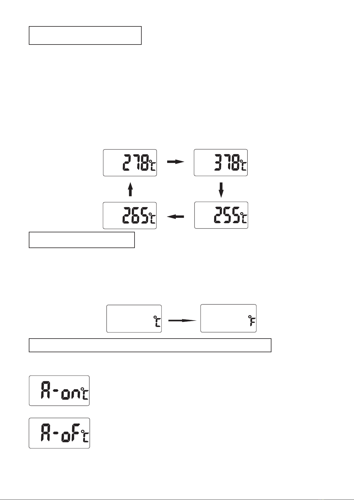
Keep pressing MODE button to increase digit
sequentially from hundred digit and release the
button when the digit you desired, then for
setting ten digit, unit digit and decimal point are
the same as hundred unit. (Please refer to
#Example 1)
Press PWR button to save Hi Temp. setting and
go to Lo Temp. alarm setting.
NOTE: The default of Hi / Lo alarm is off.
Step 3. Lo Temp. alarm select
Press MODE button to select Lo Temp. alarm ON
or OFF.
(a) When Lo Temp. alarm function is on,
press PWR button to enter Lo Temp.
alarm setting. (Move to Step 4)
(b) When Lo alarm function is off, press
PWR button to back to normal
measurement.
Hi
K
Hi
K
Lo
K
Lo
K
Step 4. Lo Temp. alarm setting
Lo
K
The meter will display “Lo Set” icons with the
default value 0°C (32°F) or the last setting on
the LCD.
Keep pressing MODE button to increase digit
sequentially from hundred digit and release the
button when the digit you desire. (Please refer to
#Example 1)
Press PWR button to save Lo Temp. setting, back
to normal measurement.
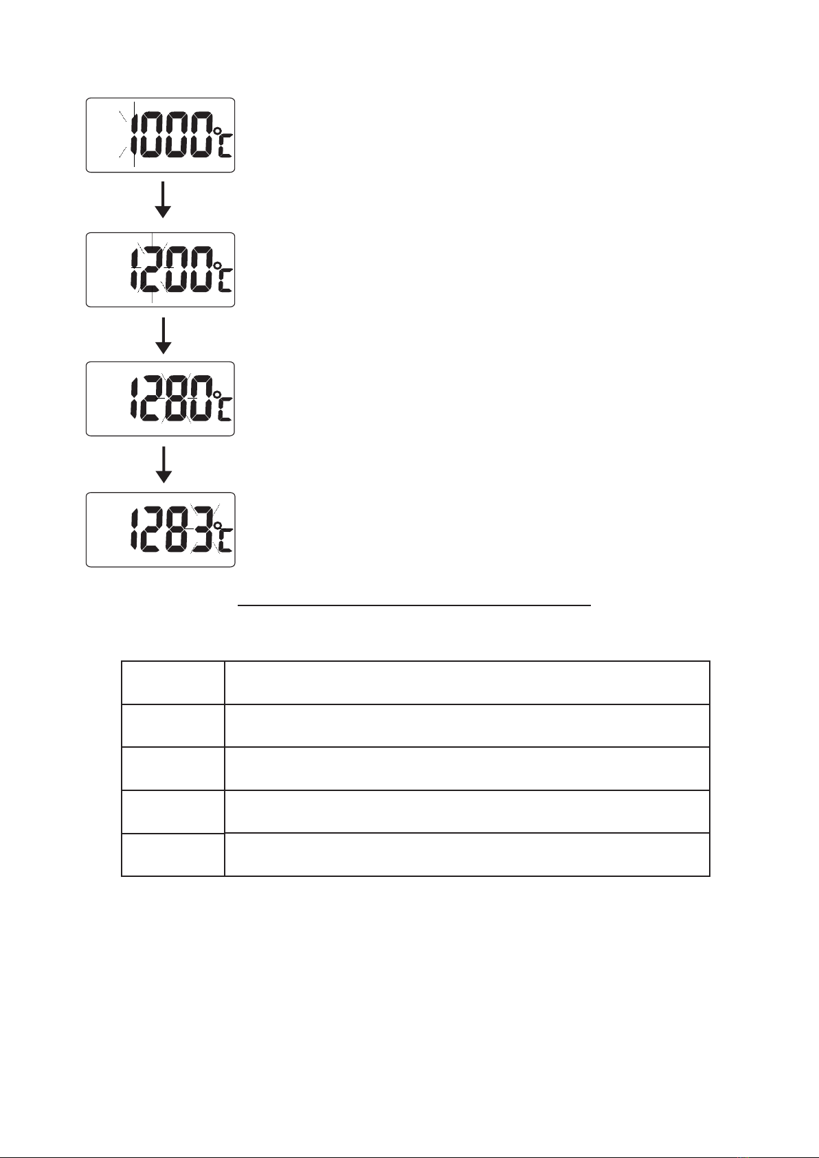
# Example 1 - Set Hi Temp. alarm at 1283°C:
Step 1.
Keep pressing MODE button, the number at unit
digit cycle from 0 to 9 then jump to tens digit from
0 to 9, too. Then the same action to hundreds
digit then thousands digit, until the thousands
digit shows ”1" then release the button.
Step 2.
Keep pressing MODE button, the same action as
Step 1. until the hundreds digit shows ”2" then
release the button.
Step 3.
Keep pressing MODE button, the same action as
Step 1. until the tens digit shows ”8" then
release the button.
Step 4.
Keep pressing MODE button, the same action as
Step 1. until the unit digit shows ”3" then release
the button.
Hi
Hi
Hi
Hi
K
K
K
K
*LCD display ”----” means disconnect thermocouple.
TROUBLE SHOOTING
Error messages:
E-2
E-5
E-6
E-3
E-4
Temperature Sensor is failed.
Humidity Sensor is failed.
Operation Temperature is too high.
Operation Temperature is too low.
Some hardware are failed.
NOTE: If above error messages appear on the display,
please contact with local distributor for
technical service.
BATTERY REPLACEMENT
When low battery indication "BAT" icon appears on the
LCD, the battery need to be replaced.
Use a coin to remove the battery compartment cover on
the rear of the meter. Replace the CR-2032 lithium
battery; install the new battery face up (+) in the battery
compartment.
BAT
K
Disposal: Follow the valid legal stipulations in respect
of the disposal device at the end of its lifecycle.
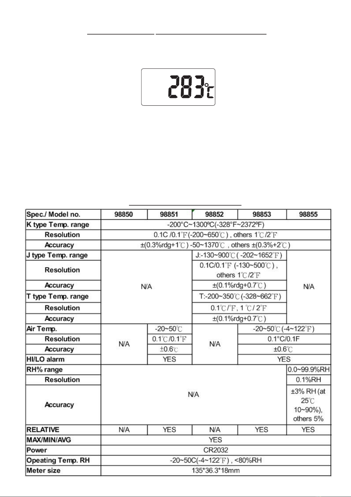
SPECIFICATION

WARRANTY
This instrument is warranted for two years from the
date of purchase against material or production
defects, in accordance with our general sales
conditions. During the warranty period the
manufacturer reserves the right to decide either to
repair or replace the product.
The two years’ warranty doesn’t apply to:
Accessories and batteries (not covered by
warranty).
Repairs made necessary by improper use
(including adaption to particular applications not
foreseen in the instructions manual) or improper
combination with incompatible accessories or
equipment.
Repairs made necessary by improper shipping
material causing damages in transit.
Repairs made necessary by previous attempts for
repair carried out by non skilled or unauthorized
personnel.
Instruments for whatever reason modified by the
customer himself without explicit authorization of
our Technical Dept.
The contents of this manual may not be reproduced in
any form whatsoever without the manufacturer’s
authorization.
This manual suits for next models
4
Table of contents


