MANUAL - Subject to alteration! Version: November 2013
ipf electronic gmbh
│
Rosmarter Allee 14 - 58762 Altena - Germany
│
Tel +49 2351 9365-0 - info@ipf-electronic.com -
www.ipf-electronic.com
1
OS / OE15 - series
Through-beam sensors
Installation and environment
Coatings on the optics impair the function and reduce the range. The installation should therefore be carried out in such
a way that as little dust as possible is deposited and no liquid can get onto them during operation. It must also be
ensured that they are accessible for cleaning.
From time to time, the optics should be cleaned with a soft cloth moistened with alcohol or soapy water.
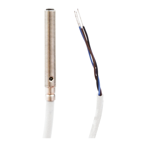
Cable
The PVC connection cable of the pre-wired cable devices is not suitable for environments containing oil or solvents and
in applications where the cable is frequently moved.
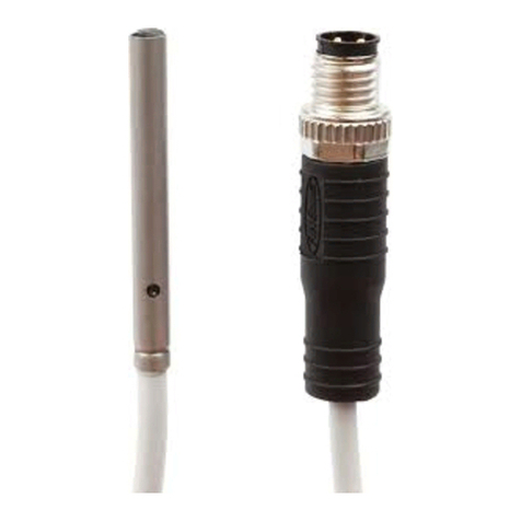
In such cases, the use of plug devices with a PUR cable socket is recommended.
Installation and alignment
1. First mount the receiver (OE) in the desired position.
2. Then temporarily mount the transmitter (OS) in its position.
3. Now align the optical axis of the transmitter on that of the receiver.
4. Finally mount the transmitter.
5. If the light beam is interrupted, the switching output of the receiver must now switch safely.
Setting
The built-in potentiometer on the receiver can be used to change the sensitivity and thus the range (distance between
transmitter and receiver). On delivery, the device is set to the maximum value. Turning it counter-clockwise reduces the
range. The full setting range of the potentiometer is 12 revolutions.
When the light beam is interrupted, the switching output switches (dark switching) and the yellow switching state LED
lights up.
Safe operation is ensured when the green function LED lights up when the light path is free and goes out when the
switching output is switched on (yellow LED lights up).
If the green LED does not light up when the light path is clear, either the sensitivity is set too low, the distance between
the devices is too great, or the optics are dirty.
When the green LED lights up, the alarm output is switched on simultaneously for the OE150700 and OE150770 variants.
The transmitter has a test input. If the black line is connected to the blue line (0V/GND), the transmitter diode is switched
off. At the same time the switching output of the receiver must switch and the yellow LED light up. If this is not the case,
either the receiver is defective or it is influenced by very strong extraneous light.

