MIC&MOD U87 User manual
U87 Build guide (2019 version)
The U87 microphone is well known all over the world. It is considered a high-quality studio
microphone, that can be used in almost all recording situations.
The U87 we present here is an exact copy of the original design.
The only thing that is changed, is the DC/DC converter. The reason for this is, that the
original DC/DC converter uses a ferroxcube core transformer, that is hard to obtain or
produce. The alternative DC/DC converter does exactly the same (that is: generate +60 and
-60 volts for the polarisation of the capsule), but uses different components.
But since the DC converter isn’t in the audio path, there is nothing to worry about.
The microphone uses three small printed circuit boards (PCBs), one for the DC/DC
converter, one for the audio circuit and a small one for the switches.
Before you start:
It is very important that you use the correct components. All resistors are color coded, so you
can find the right value by looking them up in the chart below:
But, double check the values with an ohm meter! Sometimes orange looks like red, and
68000 ohms is a different value than 6800 ohms!
But as long as you follow the instructions, there isn’t very much that can go wrong.
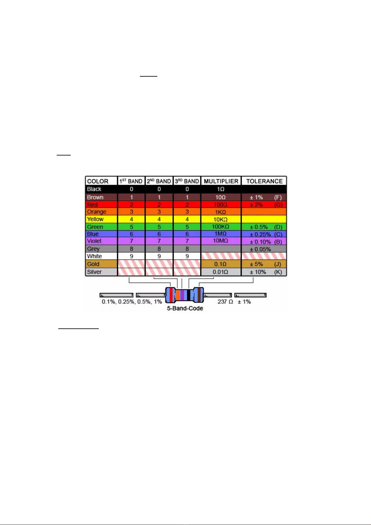
We will build the separate PCBs step by step. We will start with the DC/DC converter PCB.
First, we place and solder the two inductors, 68µH and 150µH.
The inductors look like a resistor but are a little bit bigger.
The 68µH inductor has the color code blue/grey/black, the 150µH inductor is marked
brown/green/brown. It is important that the two inductors are close together on the PCB, they
should touch each other.
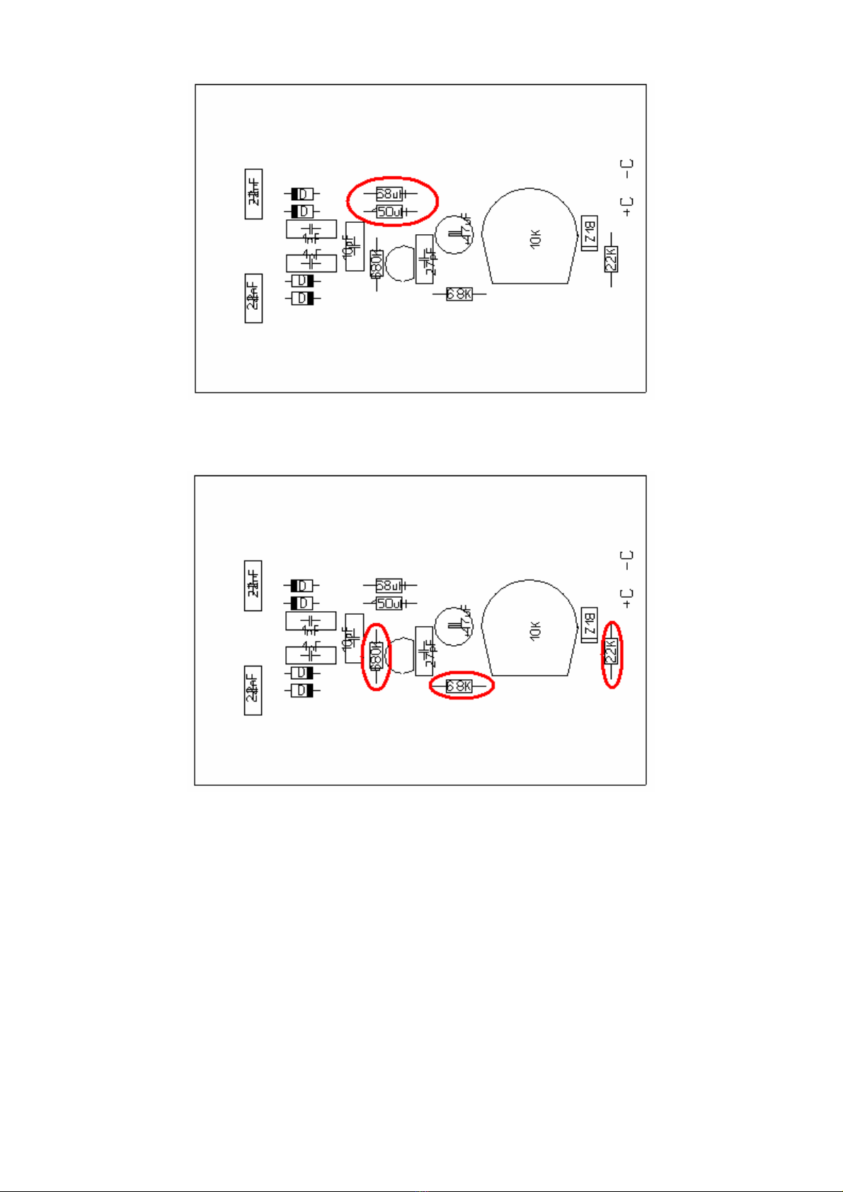
Next, place and solder 3 resistors: 22K.ohm (red/red/black/red), 6800 ohm (=6.8K,
blue/grey/black/brown) and 680K.ohm (blue/grey/black/orange).
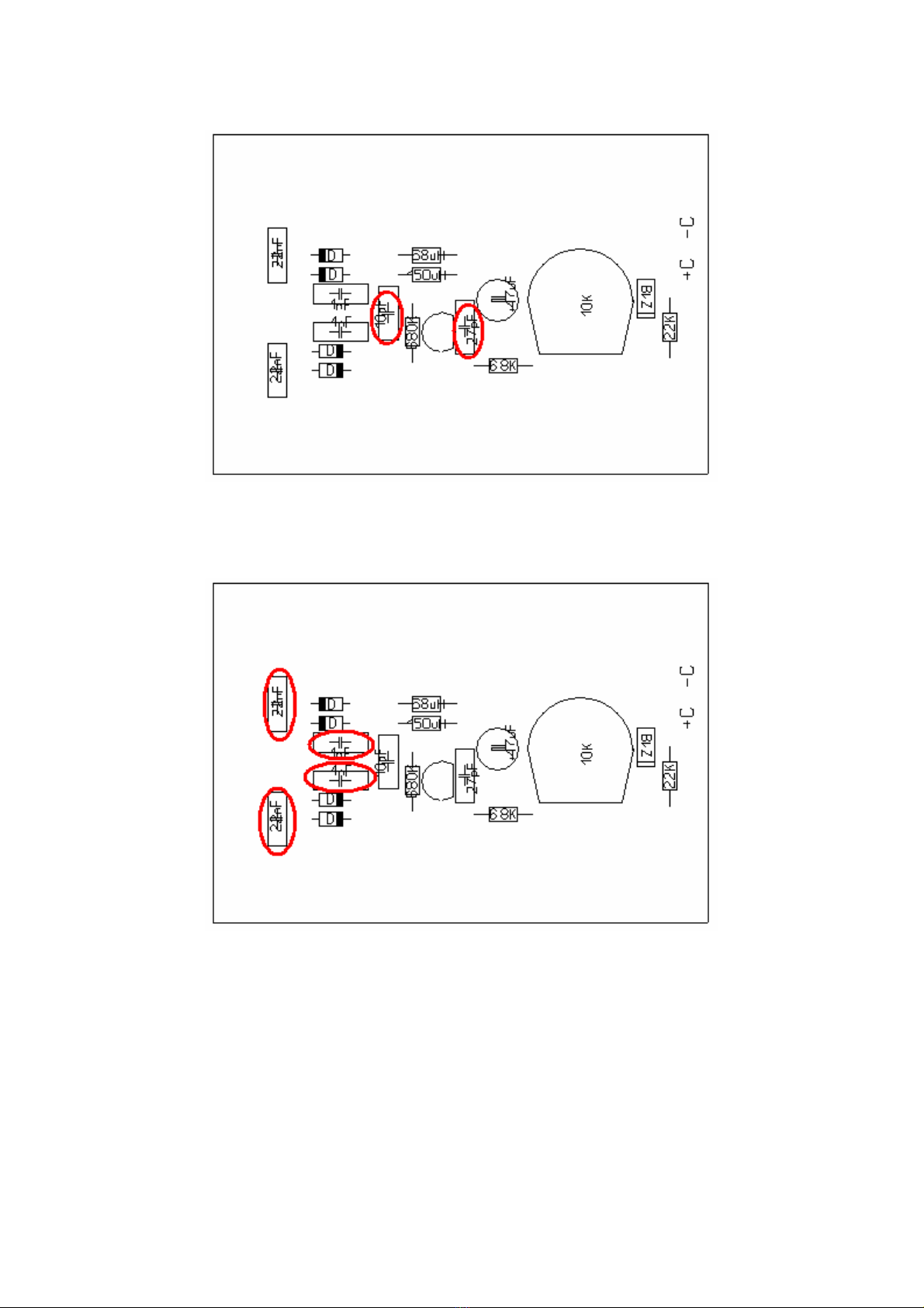
Now place the two small ceramic capacitors, 10 pF, and 27 pF. They are marked “10” and
“27”.
Place and solder two 1 nF capacitors (1nf=1000pF, “1000”) and the 22nF capacitors (22nF =
0,022 µF = “0.022”)
Insert the 47µF capacitor and observe the polarity! The ‘-‘ side is marked with a
white stripe.

Place the C547 transistor. The wires are in a triangle that matches the pattern on
the PC .
Now place and solder the four 1N4148 diodes. There are four diodes on a strip.
If you have good eyes, you can read that there is 1N4148 printed on them.
The diodes have a black ring that should correspond with the white band printed on
the PC . Don’t place them reversed!
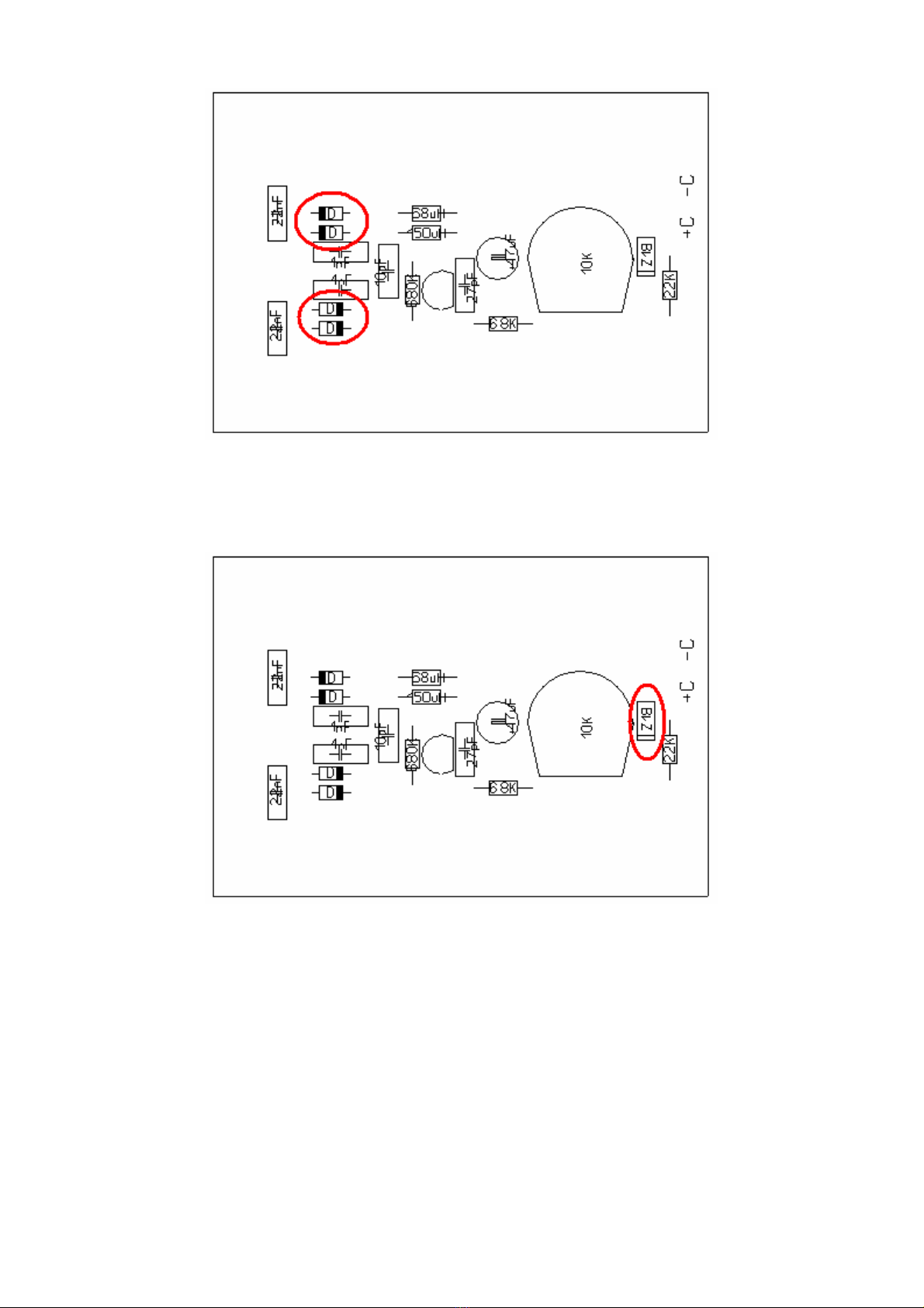
The last diode to be placed is the 18 volts Zener diode. This is one of the remaining
diodes with the ‘long’ leads. It is marked “C18”. Also, observe the correct polarity
here!
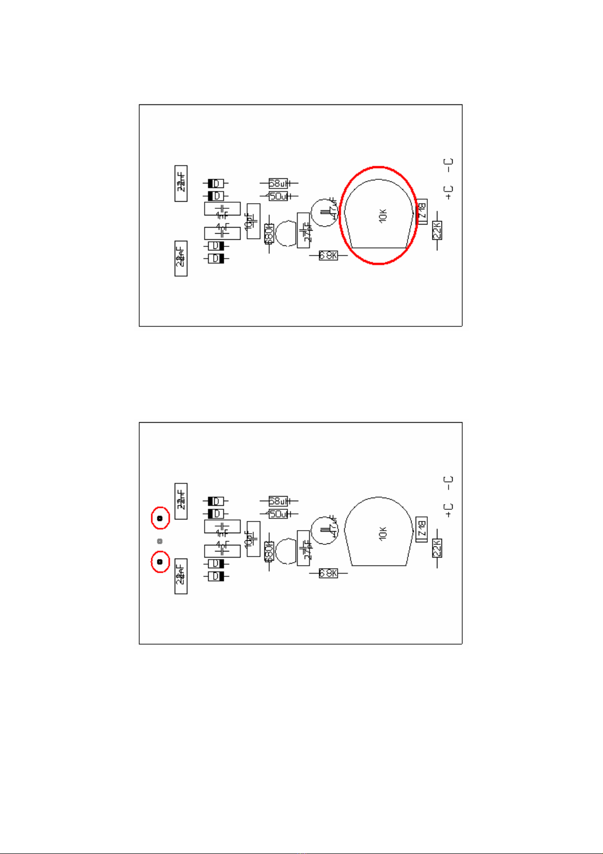
Place and solder the 10K.ohm trimmer potentiometer.
Finally, insert the two solder pins in the PC and solder them.
You may want to use a 1 mm. drill bit to make the holes in the PC a little bit bigger,
if the solder pins don’t go in easy.
Now the DC/DC converter PC is ready.
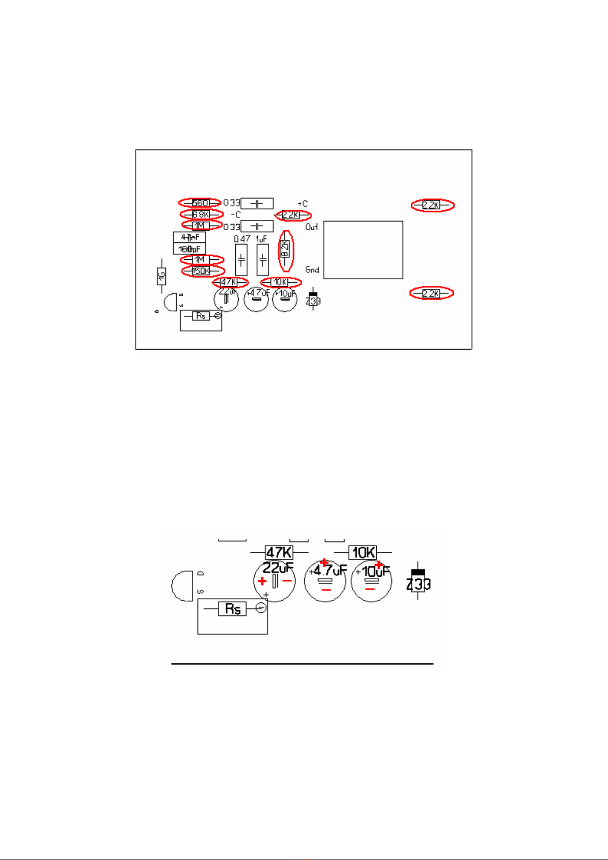
The Audio PCB.
First, we place and solder 11 resistors on the PCB.
Values are clearly marked on the screenprint.
Values are:
560 ohm green/blue/black/black
3x 2.2K.ohm (2200 ohm) red/red/black/brown
6.8K.ohm (6800 ohm) blue/grey/black/brown
8.2K.ohm (8200 ohm) grey/red/black/brown
10 K.ohm (10000 ohm) brown/black/black/red
47 K.ohm (47000 ohm) yellow/violet/black/red
150 K.ohm ( 150000 ohm) brown/green/black/orange
2x 1 M.ohm (1000000 ohm) brown/black/black/yellow
Next place and solder the three electrolytic capacitors: 4.7µF, 10µF, and 22µF.
Take care of the polarity!
Place and solder the 33v Zener diode. This is the remaining diode with the shorter wires.
Also, take care of the polarity here!

Place the red 0.33µF (=µ33) capacitors (2x), the 0.47µF (=µ47) and 1µF capacitor.
Next, there is the 47nF capacitor.
Here you have two choices: if you want to follow the original design, use the 47nF capacitor
(=0,047).
The original U87 has a filter that rolls-off the low frequencies.
40 Hz will be about -3dB referred to higher frequencies.
If you want a better LF response, you can use a 0,1µF (µ1) capacitor instead of the 47nF
one.
Also, place the 160 pF styroflex capacitor. You can use the mounting hole close to the
0,47µF capacitor.
For resistor Rs there are two options: you can use the (supplied) multiturn trimmer
potentiometer, or you can mount a fixed resistor here.
The reason for this is that the Rs (source resistor) of the FET should be matched for the
specific FET used. It is no problem to leave the trimmer potentiometer in the circuit, but
eventually, you could calibrate the circuit (described later), take out the trimmer
potentiometer and replace it with a fixed resistor of the same value.
But now we install the trimmer potentiometer anyway because the circuit is not yet calibrated.
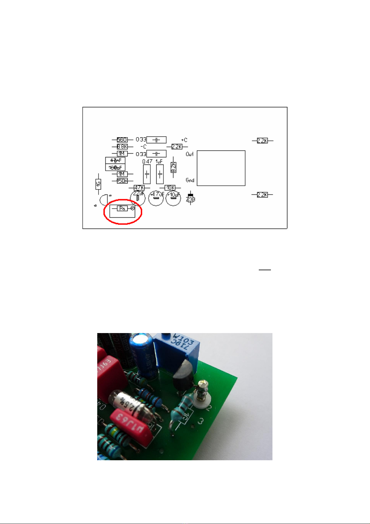
Now insert the Teflon feedthrough pin from the component side.
You can use a pair of needle nose pliers to insert it. It may take some force to put it in, but
that is how it should be; it shouldn’t fall out!
Take one of the three 1 G.ohm (brown/black/grey) resistors and solder one side to the PCB.
Fold the other end of the resistor wire in such a way that it can be soldered to the Teflon
feedthrough pin. Keep the 1 G.ohm resistor a little above the PCB, so that it doesn’t touch
the PCB.
Now take the 2N3819 FET and fold the wire in the middle carefully under an angle of 90
degrees. Now insert the two ‘outer’ wires in the PCB and solder them.
The wire we did bend before, is now soldered to the teflon feedthrough pin, together with the
wire coming from the 1 G.ohm resistor. It should look like this:
Believe it or not, but this PCB is now also almost finished!
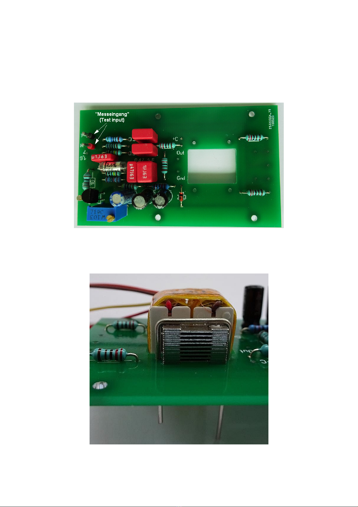
The complete PCB at this stage should now look like this:
(The 100nF capacitor was used instead of the 47nF capacitor, for a better LF response.)
The “Messeingang” or test input is optional, but you can solder a pair of short stiff wires here
to make calibration easier in a later stage.
The last thing we need to do is to mount the output transformer.
Straighten the piece of 1 mm thick wire, cut two pieces and form them into a ‘U’ shape, with
17 mm. between the ‘legs’. Insert the transformer in the rectangular hole and use the two ‘U’
wires to fasten the transformer. Cut the excess length and solder the wires.
Connect the wires coming from the transformer to the PCB.
(You may want to shorten the wires a little.)
The primary winding, red and brown wires (the outer ones on the transformer), connect to
the output of the circuit.
Red goes to “Out” and brown goes to “Gnd”.
The remaining two wires (yellow and orange/red) connect to the spots between the two 2K2
(2200 ohm) resistors. Later here the wires to the XLR connector will be added.
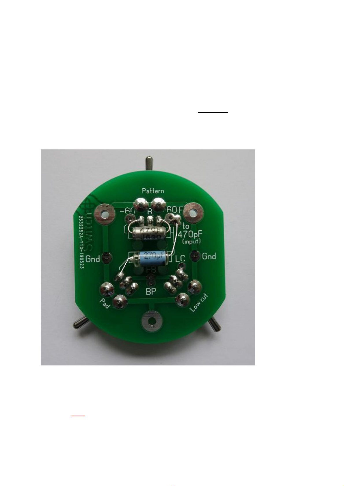
The switch PCB:
Insert and solder the three switches. Take care that the 3-position switch is placed at the
position marked “Pattern”. The 2-position switches are for the -10 dB pad and the low cut
(high-pass) filter. Make sure that the switches are flat on the board before soldering them.
With the switches in place, there are two capacitors that should be soldered to the small
switch PCB; one 470pF/630V capacitor and one 270 pF styroflex capacitor.
The 470pF should be connected between the ‘outer’ pins of the pattern switch, and the 270
pF styroflex capacitor is connected between one pin of the pattern switch and one pin of the
pad switch, as shown.
Now remove the headbasket from the microphone body and install the microphone capsule.
Be careful NOT to touch the membranes with your fingers!
Lead the 3 wires (front, rear, backplate) from the capsule through the bottom plate of the
headbasket compartment and put the headbasket back in place, to avoid damage of the
microphone capsule.

It might be a good idea to mark which wire is coming from the front membrane, and which
one is coming from the rear membrane. The wire connected to the backplate (the side of the
capsule) usually has a different color, so the function of this wire is clear.
You can lead the capsule wires through the holes in the switch PCB, the switches should be
up, the PCB should be down. Use the long M2 screws and the spacers to fasten the switch
PCB to the top of the microphone body.
The three wires coming from the capsule can now be connected to the switch PCB:
The backplate wire goes to one of the points marked ‘BP’.
The wire connected to the rear membrane connects to the center pin of the pattern switch.
The wire connected to the front membrane connects to the point where the two capacitors
are connected (this is the same point as the ‘right’ pin of the pattern switch): Like this:

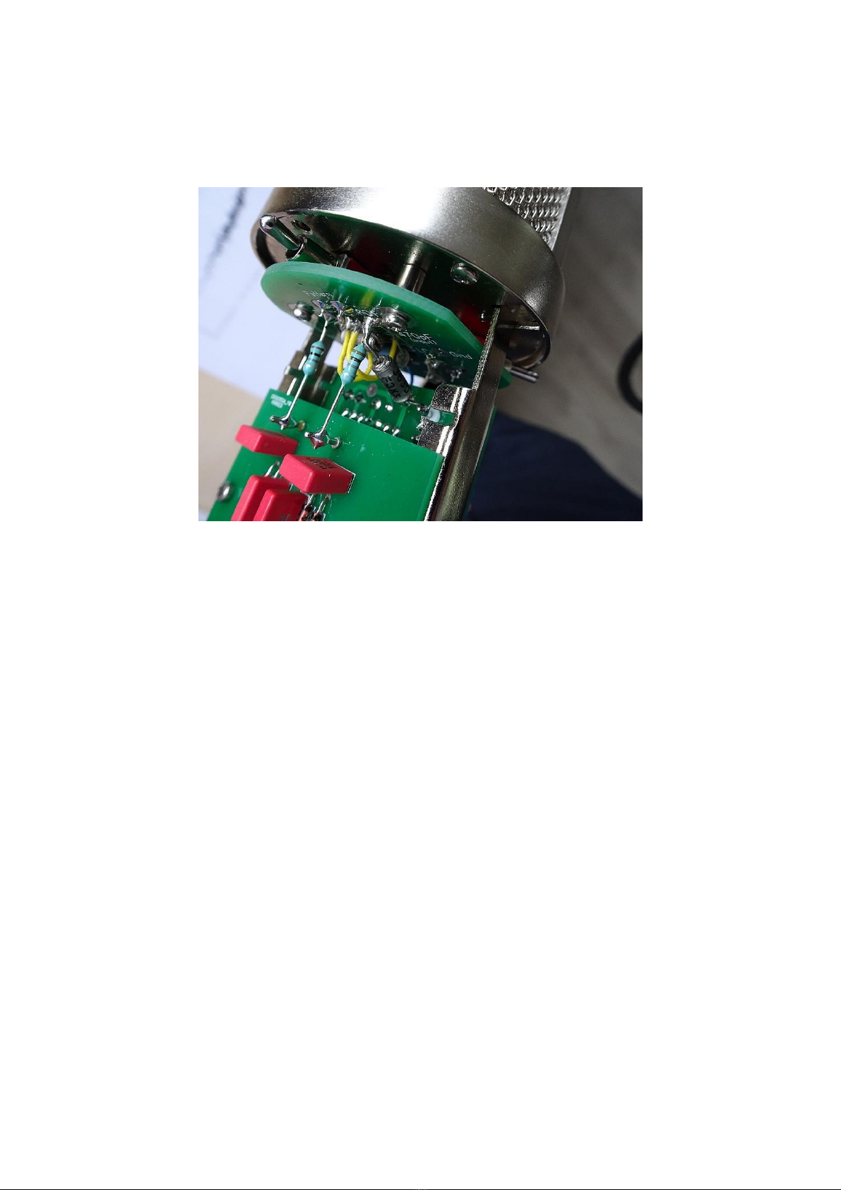
Now connect two thin wires to the points BP (where the backplate wire already is) and LC
Connect two 1 G.ohm resistors (brown/black/grey) to the two points next to the pattern
switch.
Don’t place the resistor too close to the switch PCB; leave at least 8 mm. of wire between
the resistor body and the switch PCB.
Now mount the DC/DC converter PCB with the four M2x5 screws. You can leave a
transformer screening cup in place, it will add extra stability to the mechanical structure.
Because impedances are extremely high at these points (~ 500 M.ohm), it is a good idea to
remove all flux residues with isopropyl alcohol. But don’t use alcohol on the capacitors!
Now solder the ends of the 1 G.ohm resistors we have just placed, to the solder pins of the
DC/DC converter:
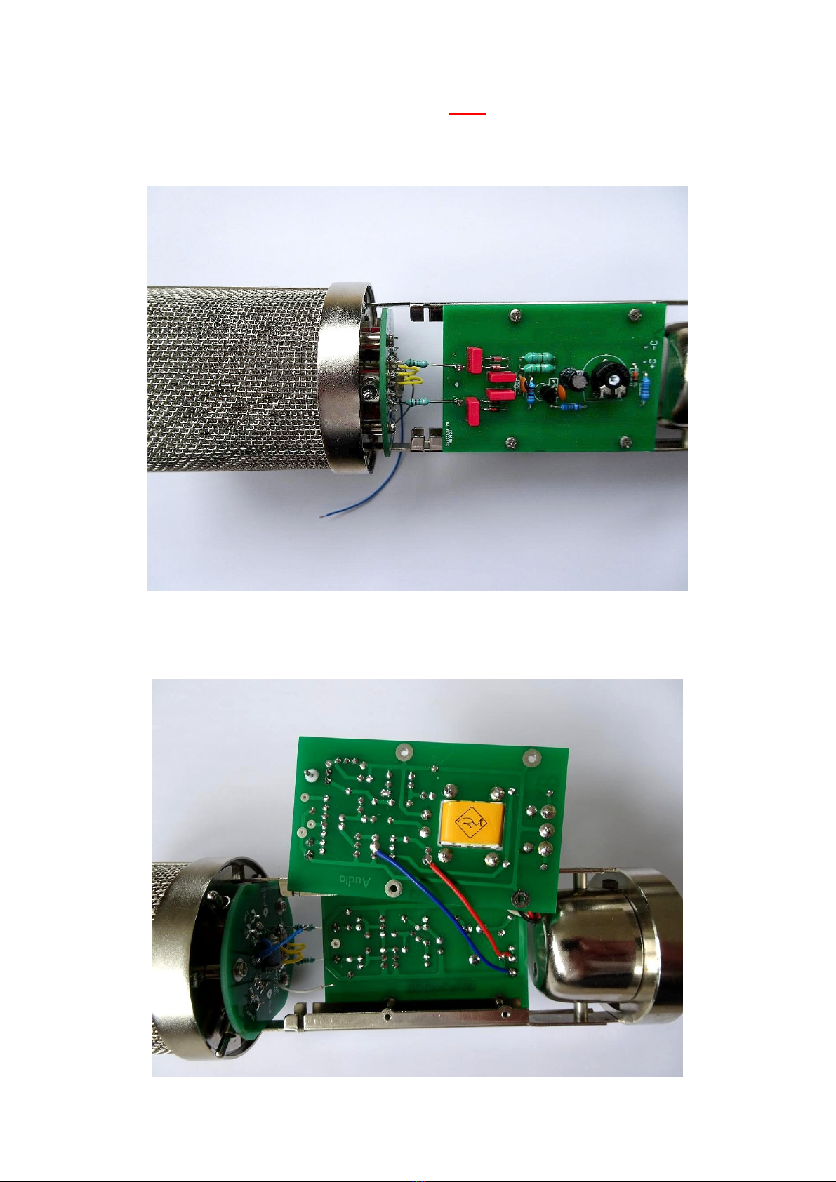
Solder two short wires to the points +C and –C of the DC/DC converter.
It is easier to do this on the copper (=solder) side of the PCB.
For clarity we used a red wire for +C and a blue wire for –C in this example.

Solder the other ends of the wires to the corresponding points (+C and –C) on the audio
PCB. (As shown in the picture.)
Now also solder the wires of the XLR connector to the audio PCB: red (pin 2), black (pin1)
and blue (pin 3). White from the XLR connects to the oranje transformer wire, red from the
XLR connects to the yellow transformer wire.
Now we have to connect the wires we have added to the small switch PCB; the wire
connected to “BP” is connected to “1,6” of the audio PCB, the wire connected to “LC” is
connected to “3” of the audio PCB. Like this:
When this is done, you can fasten the audio PCB with four M2x5 screws.
Now the last part we have to place is a bit tricky and requires some talent for “micro
surgery”...
You place and solder the last 470pF/630V capacitor between the teflon feedthrough pin on
the audio PCB (on the solder side) and one of the 1 G.ohm resistors, like this:
This is the capsule coupling capacitor. This ends the whole build process.
What remains is the calibration of the microphone.
1. Turn the black trimpot on the DC/DC converter PCB counterclockwise. (=Full left).
2. Connect the microphone to a microphone input with 48V phantom power.
3. Measure the voltage between the output pins of the DC/DC converter PCB and ground.
(The output pins are the pins where the 1 G.ohm resistors are connected to.
For ground you can use any point on the metal of the microphone body.)
4. Adjust the black trimmer potentiometer on the DC/DC converter PCB until you get +60 V
on one pin, and -60 V on the other pin. Don’t go higher than 60 volts, because this can
damage the microphone capsule! If you want to be safe, adjust the voltage even a little bit
lower than 60 volts, because the meter is probably loading the circuit a little, resulting in a
voltage drop. This means that at the moment you remove the meter, the voltage can be a bit
higher than you just measured! If you succeeded to calibrate the polarisation voltage, leave
this trimmer potentiometer alone in the future. Or even secure it with a small drop of nail
polish.
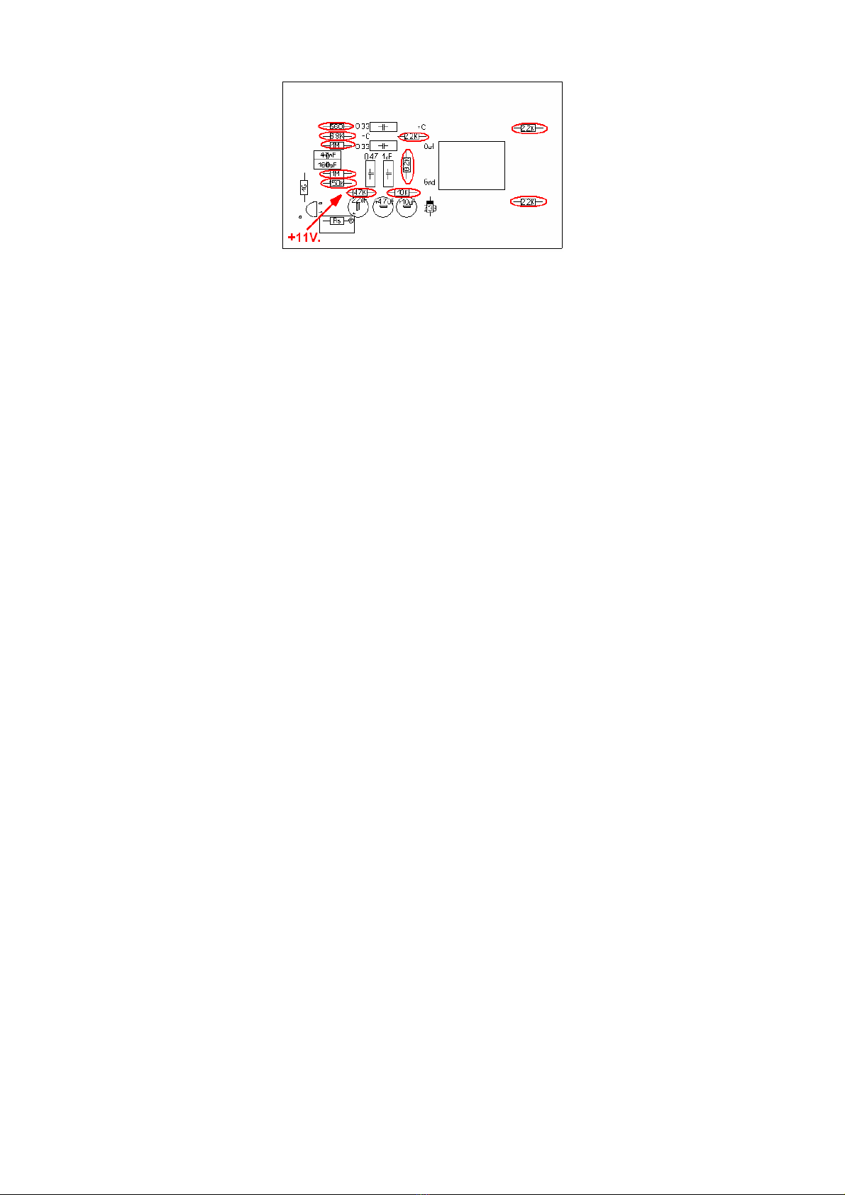
5. The next step is to set the FET bias. There are several ways to do this:
- If you don’t have any test equipment, adjust the multiturn trimmer potentiometer on the
audio PCB in such a way, that you measure +10,5 Volts on this point (one side of the
47K.ohm resistor) referred to ground (- of the meter connects to the metal of the microphone
body):
- If you have a tone generator, connect the output of the generator to the “Messeingang” (test
input) and have the microhone connected to a microphone amplifier with phantom power.
Adjust the level of the audio generator until you hear distortion. (The best signal to do this
test with, is a low distortion sinewave.) At the moment you hear distortion, turn the multiturn
trimmer on the audio PCB until the distortion gets lower or disappears. Increase the level of
the signal you are feeding into the microphone circuit until the distortion is again audible, and
try again to find the point where you get the lowest distortion in the output.
Take care that you don’t overload the input of the microphone amplifier you are using!!!
You will find one sharp point, where there is a ‘dip’ in distortion. Leave the trimmer
potentiometer at this point.
- If you have a tone generator AND and oscilloscope, you can repeat the previous procedure
but instead of listening to the signal, you oberve the output signal of the microphone
preamplifier. Adjust for the point where you get the lowest distortion at the highest output.
Note: because the microphone body is open while performing these measurements, there is
a chance that the circuit will pick up some mains hum.
When the calibration is finished, you should now have a working microphone.
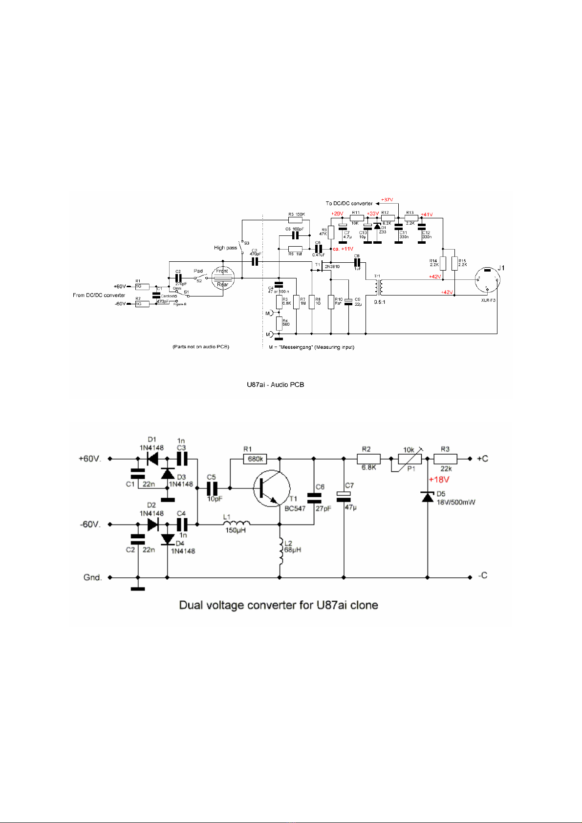
Appendix:
Audio schematic
DC converter schematic

FAQ
Q: It seems the microphone is out of phase with my other microphones.
A: Reverse the wires connected to pin 2 and 3 of the XLR insert. (Red and blue.)
Q: I want to use a different microphone capsule, is that possible?
A: Yes, but if you are using a K47 or a CK12 capsule, you should remove the 160pF
capacitor that is part of the de-emphasis filter.
Q: How critical is the adjustment of the polarisation voltage?
A: In fact, the voltage isn’t really critical. However, it is important that you don’t go higher than
60 volts, because a higher voltage could damage the capsule.
If the polarisation voltage is 54 V instead of 60 V, this will result in an attenuation of the
output signal of only 1 dB.
Q: Can I use a different FET?
A: in some cases this is possible. The 2N3819 FET was selected for its low gate capacity.
If you use a different FET, it is uncertain if it can be biased correctly in this circuit.
All FETs in the component kits were tested for noise and other parameters to make sure that
they can be biased correctly.
Q: I can’t adjust the drain voltage of the FET for 11 Volts.
A: If the voltage stays high (>20 V) or low (< 3 V) there is a chance that you damaged the
FET. All FETs were tested before they were added to the kits. If all other things are right, the
only solution is to order a new 2N3819 FET.
Q: The pattern switch does not work, or there is no sound in some positions.
A: It seems there is something wrong with the wiring of the switch PCB.
Check if the wiring corresponds with the pictures in the build description.
Q: When I change the directional pattern, or engage the low-cut or pad switch, I hear a
loud ‘pop’.
A: This is normal. The original U87ai does the same. Turn down the volume when changing
switch settings!
Q: I have a loud hum.
A: At the moment the microphone body isn’t completely closed, this is normal. The high
impedance input will act as an ‘antenna’ and picks up all (AC) voltages ‘in the air’.
Q: I have the impression that the sensitivity is lower with the low-cut switch engaged
A: That is indeed the case. The roll-off sets already in at a pretty high frequency, giving the
impression that you get a lower output with the low-cut switch in.
Q: It seems the output of the microphone is higher in the cardioid position than in the
omni- and figure-8 position.
A: That is how it should be! In the omni- and figure-8 positions both capsule halves are in
parallel, causing a reduction in sensitivity. In cardioid position, you will get the best signal to
noise ratio.

Q: The output of the microphone is much higher than from my other microphones, is
this normal?
A: Yes, the output of the U87ai is pretty high! You can always use the ‘pad’ switch, but only
use this switch if the distortion is caused by the microphone itself, because it will degrade the
signal to noise ratio.
Version 1.00 / 11-07-2019 /RvS.
Table of contents
Other MIC&MOD Microphone manuals


