Shure Microflex Advance MXA910 User manual

Overview
General Description
The Microflex®Advance™ Ceiling Array is a premium networked array microphone for AV conferencing environments, including boardrooms, huddle rooms,
and multi-purpose spaces. Revolutionary technology from the IntelliMix®DSP suite includes Steerable Coverage ™ , with eight highly directional pickup lobes
that capture participant audio from overhead. Browser-based control software provides an intuitive user interface for microphone attributes, including lobe con-
figuration, automatic mix settings, and preset templates. The microphone integrates seamlessly with Dante™ digital networked audio and third-party preset
controllers, including Crestron and AMX, to deliver a high-quality AV conferencing experience that appeals equally to integrators, consultants, and meeting
participants.
1/57©2017 Shure Incorporated
MXA910
Ceiling Array Microphone

Features
Configurable Coverage
• Steerable Coverage™ delivers precise pickup for up to 8 independent lobes
•IntelliMix®DSP Suite provides fast-acting automatic mixing, echo reduction, and channel equalization
Software Control
• Intuitive software interface provides comprehensive microphone and pattern control
• Includes templates to speed initial set-up and 10 customizable presets to import or export configurations between multiple microphones
Network Connectivity
• Discrete audio channels for each lobe and an automix channel are delivered over a single network cable
• Dante™ digital audio coexists safely on the same network as IT and control data, or can be configured to use a dedicated network
• Control strings available for third-party preset controllers including Crestron and AMX
Professional Design
• Sleek industrial design blends with contemporary board rooms and meeting spaces
• Seamless flush-mount with standard ceiling tiles
• Available in white, black, and aluminum finishes (detachable grille can be custom painted)
System Overview
① Dante audio, power, and control
Each array microphone connects to the network over a single network cable, which carries Dante™ audio, Power over Ethernet (PoE), and control information
to adjust coverage, audio levels, and processing.
② Analog audio (microphone to network)
Analog equipment, such as a wireless microphone system or a gooseneck microphone on a podium, connects to the Dante™ audio network through a Shure
Network Interface (model ANI4IN) for a completely networked conferencing system.
③ Far-end audio (network to loudspeakers)
Dante™ -enabled loudspeakers and amplifiers connect directly to a network switch. Analog loudspeakers and amplifiers connect through a Shure Network In-
terface (model ANI4OUT), which converts Dante™ audio channels into analog signals, delivered through 4 discrete XLR or block connector outputs.
④ Device control and Dante™ audio
Shure IncorporatedMXA910 Ceiling Array Microphone
2017/10/182/57

Control:A computer connected to the network controls the microphone through a web-basedcontrolapplication. Coverage, muting, LED behavior, lobe settings,
gain, and network settings are controlled remotely.
Audio: Dante™ audio is routed through Dante™ controller software. Dante™ Virtual Soundcard enables audio monitoring and recording directly on the
computer.
System Planning and Gear Requirements
Setting up the Audio Network
Shure networked conferencing systems are comprised of Microflex Advance microphones and network interfaces, which operate entirely on a Dante™ network.
Additional hardware, including network switches, computers, loudspeakers, and audio processors are described in the hardware component index.
Shure components shown in this diagram:
Microflex Advance Microphones
The MXA910 and MXA310 are equipped with Dante outputs, and connect directly to a network switch.
Audio Network Interfaces
The interfaces are used to connect analog devices such as loudspeakers and analog microphones to the network.
ANI4IN: Converts 4 analog signals (separate XLR and block connector models available) into Dante™ digital audio signals.
ANI4OUT: Converts 4 channels of Dante™ audio from the network into analog signals.
reset
PoE
INPUT
reset
PoE
INPUT
sig/clip
power
reset
PoE
network
networkaudio
encryption
1
1
2
2
3
4
3
4
OUTPUT
sig/clip
power
reset
PoE
network
networkaudio
encryption
1
1
2
2
3
4
3
4
OUTPUT
ULXD4Q
DigitalWirelessReceiver
push
control
ENTER
EXIT
SCAN
power
RF
A B
OL
OL
gainaudio
RF
A B
OL
OL
gainaudio
RF
A B
OL
OL
gainaudio
RF
A B
OL
OL
gainaudio
RX1 RX2 RX3 RX4
IR
sync sync sync sync
SEL SEL
ULXD4Q
DigitalWirelessReceiver
push
control
ENTER
EXIT
SCAN
power
RF
A B
OL
OL
gainaudio
RF
A B
OL
OL
gainaudio
RF
A B
OL
OL
gainaudio
RF
A B
OL
OL
gainaudio
RX1 RX2 RX3 RX4
IR
sync sync sync sync
SEL SEL
ULXD1 ULXD1
on
ULXD2
on
ULXD2
ULXD4Q
DigitalWirelessReceiver
push
control
ENTER
EXIT
SCAN
power
RF
A B
OL
OL
gainaudio
RF
A B
OL
OL
gainaudio
RF
A B
OL
OL
gainaudio
RF
A B
OL
OL
gainaudio
RX1 RX2 RX3 RX4
IR
sync sync sync sync
SEL SEL
ULXD4Q
DigitalWirelessReceiver
push
control
ENTER
EXIT
SCAN
power
RF
A B
OL
OL
gainaudio
RF
A B
OL
OL
gainaudio
RF
A B
OL
OL
gainaudio
RF
A B
OL
OL
gainaudio
RX1 RX2 RX3 RX4
IR
sync sync sync sync
SEL SEL
ULXD1 ULXD1
on
ULXD2
on
ULXD2
Dante
Analog
Microflex Advance microphones
Analog microphones
Loudspeakers
Option 1 (VOIP/TELCO)
Option 2 (Internet/DVS)
Near end Far end
Network switch
Network interface (ANI4IN)
Network interface (ANI4OUT)
This diagram shows the entire signal path through a networked conference system. Signals from the near end and far end are exchanged through an audio
processor connected to a phone system, or through a computer connected to the internet. Analog microphones connect to the network through the Shure ANI4IN,
while loudspeakers connect through the Shure ANI4OUT.
Shure IncorporatedMXA910 Ceiling Array Microphone
3/572017/10/18

sig/clip
power
network
networkaudio
encryption
1
2
3
4
sig/clip
power
network
networkaudio
encryption
1
2
3
4
sig/clip
power
network
networkaudio
encryption
1
2
3
4
ROOM ASIGNAL ROOM BSIGNAL
sig/clip
power
network
networkaudio
encryption
1
2
3
4
sig/clip
power
network
networkaudio
encryption
1
2
3
4
MXA910
MXA910
MXA310
MXA310
ANI4IN
ANI4IN
ANI4OUT
ANI4OUT ANI4OUT
NETWORK SWITCH
NETWORK SWITCH NETWORK SWITCH
VIDEO CODEC
VIDEO CODEC VIDEO CODEC
LOUDSPEAKERS ANALOG MICROPHONES
1
1
1
2
2
2
3
3
4
4
4
5
55
6
6
6
7
7
8
8
Dante Signals
Analog Signals
This diagram shows Microflex Advance components in context, with two rooms communicating through video codecs.
Controlling Hardware and Audio Over the Network
Audio and hardware settings are managed through a computer connected to the same network.
Shure Hardware and Audio
Each Microflex Advance component has a web application which provides mixing and configuration tools to optimize sound quality.
Expanded Control for Analog Devices
Analog devices that are connected to the network through a Shure network interface (ANI4IN/ANI4OUT) benefit from additional remote control: Volume levels,
equalization, and signal routing are managed through the web application. For example, adjusting loudspeaker volume or muting a wired microphone, which
would normally be done from the hardware, can now be controlled remotely over the network.
Dante™ Signal Routing
Signal routing between devices is managed through Dante Controller software, provided by Audinate™ .
Shure IncorporatedMXA910 Ceiling Array Microphone
2017/10/184/57

Hardware Component Index
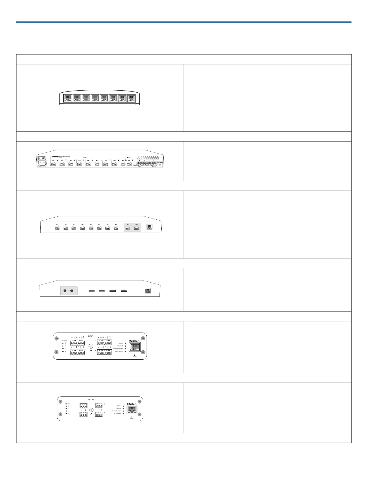
Network Switch
The network switch provides central connectivity for all networked components.
Audio from any networked Shure microphones that are connected to the switch
can be routed to any Dante™ -enabled device. The switch sends and receives
audio and control data, while simultaneously powering the microphones and
audio network interfaces through PoE (Power over Ethernet). See the network
switch requirements for additional details.
Power over Ethernet (PoE) Requirements:
All Shure components included in these scenarios require Power over Ethernet
(class 0). If not provided through the network switch, a PoE injector is required
to power the devices.
Shure Microflex Wireless Audio Network Interface (MXWANI)
The Microflex Wireless Audio Network Interface (MXWANI) is a digital-to-analog
breakout box with a built-in gigabit network switch. It converts digital audio from
the network into analog signals for signal processing or amplification, and
provides PoE over one network port to power a device. For details, refer to the
Microflex Wireless user guide, available at http://www.shure.com.
Audio Processor
The audio processor sends and receives audio through a VOIP server or a
standard phone line. They also provide digital signal processing, such as
acoustic echo cancellation.
Dante™ -enabled
Processors that support Dante™ connect directly to the network switch to re-
ceive audio from Microflex Advance microphones.
Analog
When using an analog processor, a converter (such as the Shure ANI4OUT
or MXWANI) is required to deliver the analog audio from Microflex Advance
microphones to the processor.
Video Codec
Like the audio processor, the codec sends and receives audio signals alongside
video signals between the near end and the far end. Audio from the near end
must connect to the audio input on the video codec, which is typically a stereo
analog connection. The Shure ANI4OUT Audio Network Interface converts the
audio to an analog signal for connecting to a codec.
Shure ANI4IN Audio Network Interface (Analog-to-Dante Converter)
The Shure ANI4IN Audio Network Interface converts 4 channels of analog audio
into independent digital audio channels on a Dante™ network. Adjustable gain
and +48V phantom power deliver the flexibility to support line, auxiliary, and
microphone-level devices. For networked conferencing systems, the Audio
Network Interface provides a simple way to connect previously installed analog
equipment onto the audio network, such as wireless microphones for presenters.
The web application gives technicians and administrators control over channel
levels and settings from any computer connected to the same network.
sig/clip
power
reset
PoE
network
network audio
encryption
1
1
2
2
3
4
3
4
INPUT
Shure ANI4OUT Audio Network Interface (Dante-to-Analog Converter)
The Shure ANI4OUT Audio Network Interface converts 4 channels of Dante™
digital audio into discrete analog signals. Available in both XLR and block
connector versions, each box uses a single network cable to receive audio and
power using PoweroverEthernet (PoE). The web application gives technicians
and administrators control over channel levels and settings from any computer
connected to the same network.
sig/clip
power
reset
PoE
network
network audio
encryption
1
1
2
2
3
4
3
4
OUTPUT
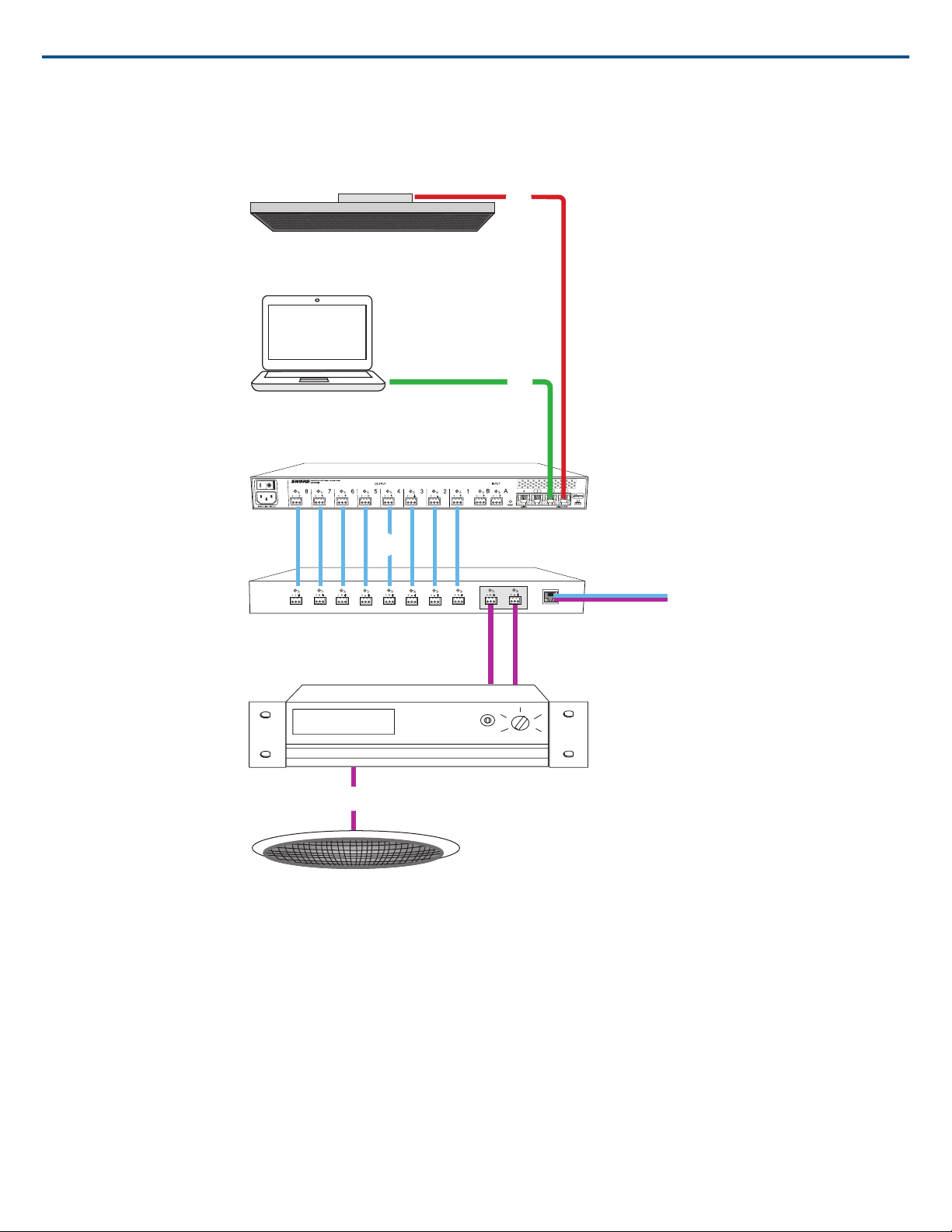
Amplifiers and Loudspeakers
Shure IncorporatedMXA910 Ceiling Array Microphone
5/572017/10/18

Audio from the far end is routed to local loudspeakers. Dante™ -enabled
speakers or amplifiers connect directly to the network switch, while analog
systems require an audio network interface to receive networked audio.
Computers and Control Systems
Browser-Based Web Application
A computer connected to the network provides control of Shure networked
components through the web application for each device.
Dante™ Software
A computer running Dante™ Virtual Soundcard, Dante™ Controller, and web
conferencing software is used to send and receive audio between the nearend
and far end.
Control Systems (AMX, Crestron, etc.)
If using a third-party control system, Microflex Advance microphones send and
receive commands over Ethernet. If an analog logic signal must be sent over
the network, the Shure ANI4IN Audio Network Interface receives analog logic
signals and converts them into Ethernet control strings.
System Scenarios
The following diagrams show a selection of common conferencing room systems. Use them as a reference when planning hardware and cable requirements
for an installation. Each diagram includes:
• Signal flow and connections
• Required hardware
• Component roles
Power Over Ethernet and Hardware Requirements
All Shure components included in these scenarios require Power over Ethernet (PoE, class 0). Refer to the Dante and Networking section for additional infor-
mation on cable and network switch requirements.
Shure IncorporatedMXA910 Ceiling Array Microphone
2017/10/186/57

Telephone Conference with Shure MXW Network Interface
Ceiling array microphone
Software control
MXW Audio Network Interface
Audio processor
Amplifier
Ceiling speaker
① Array microphone to Shure MXWANI
Connect the microphone output to port 1 on the MXWANI with a network cable. Port 1 provides the necessary Power over Ethernet (PoE).
② Computer to Shure MWXANI
Connect a computer to the ANI on port 2 or 3 with a network cable to provide control of the array microphone and other networked components.
③ Shure ANI analog outputs to audio processor
Step 1: Route signals with Dante™ Controller software
Route the channels from the microphone (Dante transmitter) to the MXWANI channels (Dante receiver). This establishes the discrete channels to deliver through
the analog outputs.
Step 2: Connect the MXWANI outputs to the processing device inputs
Block connector outputs on the MXWANI send balanced audio signals to the inputs on the processing device, which provides digital signal processing (such as
acoustic echo cancellation).
④ Connection to far end
Connect the audio processor to a VOIP server or telephone line to send and receive audio between the near end and far end.
Shure IncorporatedMXA910 Ceiling Array Microphone
7/572017/10/18

⑤ Audio from far end to amplifier
Route the far end audio through the audio processor output to an amplifier.
⑥ Amplified audio signal to loudspeakers
Connect the loudspeakers to the amplifier to hear the audio from the far end.
Telephone Conference with Dante™ -enabled Audio Processor
Ceiling array microphone
Software control
Network switch
Dante audio processor
Amplifier
Ceiling Speaker
① Array microphone to network switch
Connect the array microphone output with a network cable to any port on the switch that supplies Power over Ethernet (PoE).
② Computer to network switch
Connect a computer to the network switch to provide control of the array microphone and other networked components.
③ Network switch to Dante™ audio processor
Connect the Dante™ audio processor to the network switch to provide:
• Digital signal processing (acoustic echo cancellation)
• Digital-to-analog conversion to deliver Dante™ audio over an analog (VOIP or telephone line) output.
Shure IncorporatedMXA910 Ceiling Array Microphone
2017/10/188/57

• Analog-to-digital conversion to deliver analog audio from the far end onto the Dante™ network.
④ Connection to far end
Connect the output from the audio processor to a VOIP server or telephone line to deliver audio between the near end and far end.
⑤ Audio from far end to amplifier
Route the far end audio through the audio processor output to an amplifier.
⑥ Amplified audio signal to loudspeakers
Connect the loudspeakers to the amplifier to deliver the audio from the far end.
Telephone Conference with Network Interfaces and Audio Processor
sig/clip
power
reset
PoE
network
network audio
encryption
1
1
2
2
3
4
3
4
OUTPUT
sig/clip
power
reset
PoE
network
network audio
encryption
1
1
2
2
3
4
3
4
OUTPUT
Ceiling array microphone
Software control
Network switch
Shure ANI4OUT
Amplifier
Ceiling speaker
① Array microphone to network switch
Connect the array microphone output with a network cable to any port on the switch that supplies power over ethernet (PoE).
Shure IncorporatedMXA910 Ceiling Array Microphone
9/572017/10/18

② Computer to network switch
Connect a computer to the network switch to provide control of the array microphone and other networked components through the software control panel.
③ ANI4OUT (digital-to-analog conversion)
From the network switch: Use network cables to connect each ANI4OUT to the network switch. A single ANI4OUT receives 4 channels of Dante™ audio,
and converts them to 4 analog signals, delivered through XLR outputs or block connectors. Using two of them, all 8 channels from the array microphone can
be connected to analog inputs on an audio processing device.
To a processing device: Route the ANI4OUT outputs to the processing device inputs to provide digital signal processing (acoustic echo cancellation).
④ Connection to far end
Connect the output from the audio processor to a VOIP server or telephone line to deliver audio between the near end and far end.
⑤ Audio from far end to amplifier
Route the far end audio through the audio processor output to an amplifier.
⑥ Amplified audio signal to loudspeakers
Connect the loudspeakers to the amplifier to deliver the audio from the far end
Shure IncorporatedMXA910 Ceiling Array Microphone
2017/10/1810/57

Web Conferencing Software With Dante™ Virtual Soundcard
reset
PoE
OUTPUT
Ceiling array microphone
Network switch
Shure ANI4OUT
Ceiling speaker
① Array microphone to network switch
Connect the array microphone output with a network cable to any port on the switch that supplies Power over Ethernet (PoE).
② Computer to network switch
Connect a computer to the network switch to provide control of the array microphone and other networked components through the software control panel. The
computer also runs Dante™ Virtual Soundcard, Dante™ Controller, and the web conferencing software.
Shure IncorporatedMXA910 Ceiling Array Microphone
11/572017/10/18

•Dante™ Virtual Soundcard / Controller: Turn on the Dante™ Virtual Soundcard and use the controller software to route the array microphone signal to
the computer.
•Web Conferencing Software:Assign the audio input and output device settings to the appropriate Dante transmitter and receiver channels.
③ Network switch to ANI4OUT
Use network cables to connect each ANI4OUT to the network switch. Each interface receives 4 channels of Dante audio, and converts them to 4 analog signals,
delivered through XLR outputs or block connectors.
④ Audio from far end to amplifier
Route the far end audio to an amplifier.
⑤ Amplified audio signal to loudspeakers
Connect the loudspeakers to the amplifier to deliver the audio from the far end.
Shure IncorporatedMXA910 Ceiling Array Microphone
2017/10/1812/57

Video Conference
sig/clip
power
reset
PoE
network
network audio
encryption
1
1
2
2
3
4
3
4
OUTPUT
Ceiling array microphone
Software control
Network switch
Shure ANI4OUT
Video codec
Ceiling speaker
① Array microphone to network switch
Connect the array microphone output with a network cable to any port on the switch that supplies power over ethernet (PoE).
② Computer to network switch
Connect a computer to the network switch to provide control of the array microphone and other networked components through the software control panel.
③ ANI4OUT (digital-to-analog conversion)
Each ANI4OUT receives 4 channels of Dante audio, and converts them to 4 analog signals, delivered through XLR outputs or block connectors.
Input: Connect the ANI4OUT to the network switch with a network cable
Ouput: Connect the analog output to the audio input on the video codec
Shure IncorporatedMXA910 Ceiling Array Microphone
13/572017/10/18

④ Video codec connection to far end
Connect the codec to the appropriate network to connect with the far end.
⑤ Audio from far end to amplifier
Route the far end audio through the video codec audio output to an amplifier.
⑥ Amplified audio signal to loudspeakers
Connect the loudspeakers to the amplifier to deliver the audio from the far end.
Installation
Microphone Placement
Room Variables
Optimal microphone placement is determined by the seating arrangements and infrastructure. Follow these guidelines for the best possible results:
• In rooms with flexible furniture arrangements or multiple array microphones, use the microphone configuration tool in the web application to ensure that the
coverage is adequate for all seating scenarios.
•The lobes should be pointed towards the front of each talker. Carefully consider placement in rooms where talkers may face a screen during a video conference.
• Avoid installing the microphone directly next to unwanted sound sources, such as air vents or noisy video projectors.
• Consider installing acoustic treatment to improve speech intelligibility in rooms that are too reverberant.
Mounting Height
The maximum mounting height that can be set in the ceiling array microphone web application is 30 feet (9.14 meters). In a typical acoustic environment1, the
microphone maintains an "A" rating based on the STIPA2(Speech Transmission Index for Public Address systems) international standard at distances up to
16 feet between the microphone and talker. In better acoustic environments, the STIPA "A" rating may extend beyond 16 feet.
Consider the following when determining a mounting height:
•The pickup pattern of the ceiling array is narrower than a shotgun microphone, and therefore it can be placed farther from the source than any other microphone.
While the web application shows an ideal coverage zone for each channel, keep in mind that there is no specific barrier at which the audio degrades or
gates off. Lobe sensitivity data is available for each width setting in the product specifications.
• Like all microphones, tonality changes as the distance from the source increases.
• The intelligibility scale helps to predict how the microphone will sound at a given height.
• The coverage area of the lobes increases at farther distances.
[1] Room conditions: RT60 (reverb time) = 500 ms @ 1kHz, A weighted room noise = 40dBSPL(A)
[2] IEC-602682-16 standard
Intelligibility Scale
The intelligibility scale objectively compares the acoustic performance of the array microphone with a cardioid gooseneck microphone at various distances. This
information is useful for predicting how the array microphone will perform at a given distance and to determine an ideal mounting height. The data in the intelli-
gibility scale table is derived from measuring the microphones to meet an equivalent value from the SpeechTransmission Index IEC-602682-16 standard.
Distances With Equivalent Speech Transmission Index Values
Cardioid Gooseneck Microphone (Distance to Talker)Ceiling Array Microphone (Distance to Talker)
3.75 feet (1.14 m)6 ft (1.83 m)
5 feet (1.52 m)8 ft (2.44 m)
6.25 feet (1.91 m)10 ft (3.05 m)
7.5 feet (2.29 m)12 ft (3.66 m)
Data was collected in a typical huddle room with the following measurements:
•Reverberation decay time: 500 ms @ 1kHz
•Noise floor: 40 dB SPL (A-weighted)
Note: These values are specific to the described room. In a well-controlled acoustic environment, the array microphone may perform with equivalent Speech
Transmission Index values at even greater distances. In highly reverberant rooms, the performance is less predictable.
A = Distance between array microphone and talker
Shure IncorporatedMXA910 Ceiling Array Microphone
2017/10/1814/57

B = Distance between cardioid microphone and talker
B
A
In this example, the acoustic performance of the array microphone mounted (A) feet from the talker matches the cardioid gooseneck microphone placed at a
distance of (B) feet from the talker.
FyreWrap®Fire Protective Wrap System Installation
The FyreWrap®fire protective wrap system included with the Microflex®Advance™ MXA910 ceiling array microphone must be installed to meet the UL 2043
plenum rating (suitable for air handling spaces).
Installation
1. Make sure the microphone surface is clean to ensure proper adhesion
2. Remove the paper backing from the 4 adhesive pads on the fire wrap system
3. Align the fire wrap system over the microphone and secure it by applying gentle pressure over the adhesive pads
Note: make sure to leave enough space to install the Ethernet cable and safety tether (if required).
Shure IncorporatedMXA910 Ceiling Array Microphone
15/572017/10/18

Shure IncorporatedMXA910 Ceiling Array Microphone
2017/10/1816/57

Installing the Array Microphone
Before you begin:
• Remove the protective plastic cover from the microphone
• Verify the ceiling tile size matches the appropriate model variation
• If using the optional junction box or adapter accessories, install them on the microphone prior to ceiling installation
Model Variations
ColorCeiling Grid SizeModel
Black2 x 2 ft (60.9 x 60.9 cm)MXA910B
White2 x 2 ft (60.9 x 60.9 cm)MXA910W
Aluminum2 x 2 ft (60.9 x 60.9 cm)MXA910AL
Black60 x 60 cm (23.6 x 23.6 in)MXA910B-60CM
White60 x 60 cm (23.6 x 23.6 in)MXA910W-60CM
Aluminum60 x 60 cm (23.6 x 23.6 in)MXA910AL-60CM
---25 mm expander fits onto 60 cm model, for 62.5 x 62.5 cm installationA910-25MM (Adapter)
------A910-JB (Junction box accessory)
Note: see product specifications for array microphone dimensions.
Ceiling Tile Mounting
The array microphone mounts directly in a ceiling tile grid. The microphone is available in two sizes, with an optional adapter kit also available to provide solutions
for the most common ceiling tile sizes.
IMPORTANT: Do not install the 60 cm model into a 2 ft (609.6 mm) ceiling grid.
Rubber Scratch Protectors
Optional: Before installing the microphone into the ceiling, attach the included rubber pads on the corners of the microphone to prevent scratching.
Shure IncorporatedMXA910 Ceiling Array Microphone
17/572017/10/18

Ceiling Grid Runner
Rubber Pad
Array Microphone
Installation
1. Remove the tile from the ceiling grid where the array microphone will be installed.
2. Run the Ethernet cable above the ceiling grid and through the opening in the ceiling.
Note: An optional junction box accessory (model A910-JB) mounts on the microphone to directly connect conduit.
3. Plug the Ethernet cable into the array microphone output.
4. Install the microphone into the ceiling grid.
Shure IncorporatedMXA910 Ceiling Array Microphone
2017/10/1818/57

Using the Adapter (625 mm Tile Size)
For ceiling grids which measure 625 x 625 mm, attach the adapter to the array microphone and then follow the ceiling tile mounting instructions.
Note: Only for use with the 60 x 60 cm model
Screw the adapter pieces on as shown, using 2 screws per side.
Other Ceiling Tile Sizes
Mounting the microphone in a grid of a different size requires using a suspension mount option or modifying the ceiling grid.
Safety Tether
Shure IncorporatedMXA910 Ceiling Array Microphone
19/572017/10/18

Attach a safety tether between the building structure and one of the tie-off points on the back panel of the microphone. This safety measure prevents the microphone
from falling in an emergency situation. Make sure there is no tension on the safety tether to ensure the microphone is resting properly in the ceiling grid.
Important: Follow local regulations when attaching the safety tether.
Suspension Mounting
① Wire Suspension Hanging Points (4 mm hole size)
② VESA Mounting Holes
4-point Wire Suspension
Secure the microphone to the ceiling using braided metal cable or other high-strength wire. Use the 4 integrated hanging points on the back of the microphone
to securely attach the cable. The hole size in the hanging points is 4 mm (0.15 in).
VESA Standardized Mounting
The rear plate on the microphone has 4 threaded holes for attaching the microphone to a VESA mounting device. The mounting holes follow the VESA MIS-D
standard:
• Screw specification: M4 thread (Microphone threaded hole depth = 9.15 mm)
• Hole spacing: 100 mm (square)
Cable Management
To keep the Ethernet cable out of view, use the appropriate method based on the installation type.
Cable SolutionInstallation
Run the cable above the ceiling gridCeiling tile
Guide the cable through the pole to run it above the ceiling gridVESA (pole mounting)
Use cable ties to attach the CAT5 cable along one of the hanging wires4-point wire suspension
Note: If using conduit to contain the cable, the optional junction box accessory (model A910-JB) mounts directly to the rear panel of the microphone.
Painting Components
The grille and frame of the array microphone can be painted to blend in with room design. Some basic disassembly is required for painting.
Step 1: Removing the Frame and Grille
1. Remove the screws that hold the main assembly on the frame (6 screws per side). There are washers between these screws and the rear panel.
Important: Do not remove the screws that are farthest in the corner and recessed into the panel (see graphic).
2. Carefully lift the assembly out of the frame.
Shure IncorporatedMXA910 Ceiling Array Microphone
2017/10/1820/57
Other manuals for Microflex Advance MXA910
3
Table of contents
Other Shure Microphone manuals

Shure
Shure SM35 User manual

Shure
Shure 596LB User manual

Shure
Shure PG ALTA PGA 57 User manual

Shure
Shure Microflex MXCW User manual

Shure
Shure MODULINK 810 User manual

Shure
Shure MXA920 User manual

Shure
Shure Unidyne A PE58 User manual

Shure
Shure SM58 User manual

Shure
Shure PE25L Series User manual

Shure
Shure MV7 User manual

Shure
Shure Unidyne B 515BG User manual

Shure
Shure PG48 User manual

Shure
Shure ROSWELLITE KSM353/ED User manual

Shure
Shure BETA 56A User manual

Shure
Shure R191 Use and care manual

Shure
Shure 404B User manual

Shure
Shure MXCW User manual

Shure
Shure QLX-D User manual

Shure
Shure PGA 98D User manual

Shure
Shure PG 30 User manual