Michi S5 User manual

Owner’s Manual
Manuel de l’utilisateur
Bedienungsanleitung
Manual de Instrucciones
Manuale di istruzioni
Instruktionsbok
Инструкция пользователя
S5
Stereo Power Amplifier
Amplificateur Stéréo Intégré
Stereo-Endverstärker
Etapa de Potencia Estereofónica
Stereo eindversterker
Amplificatore finale stereo
Integrerad stereoförstärkare
Интегрированный стерео усилитель
M8
Monoblock Power Amplifier
Amplificateur de Puissance Mono
Mono-Endverstärker
Etapa de Potencia Monofónica
Monoblock eindversterker
Amplificatore finale mono
Monoblock effektförstärkare
Моноблочный усилитель мощности

2S5 Stereo Power Amplifier / M8 Monoblock Power Amplifier
Notice
The RS232 connection should be handled by
authorized persons only.
WARNING: There are no user serviceable parts
inside. Refer all servicing to qualified service
personnel.
WARNING: To reduce the risk of fire or electric
shock,donotexposetheunittomoistureorwater.
Do not expose the unit to dripping or splashing.
Do not place objects filled with liquids, such as
vases, on the unit. Do not allow foreign objects
to get into the enclosure. If the unit is exposed
to moisture, or a foreign object gets into the
enclosure, immediately disconnect the power
cord from the wall. Take the unit to a qualified
service person for inspection and necessary
repairs.
Read these instructions.
Keep these instructions.
Heed all warnings.
Follow all instructions.
Do not use this apparatus near water.
Clean only with dry cloth.
Do not block any ventilation openings. Install in
accordancewiththemanufacturer’sinstructions.
Do not install near any heat sources such as
radiators, heat registers, stoves, or other
apparatus (including amplifiers) that produce
heat.
Do not defeat thesafety purpose ofthe polarized
or grounding-type plug. Apolarized plughas two
blades withone widerthanthe other. A grounding
type plug has two blades and a third grounding
prong. The wide blade or the third prong are
providedforyour safety. If the provided plug does
not fit into your outlet, consult an electrician for
replacement of the obsolete outlet.
Protect the power cord from being walked on
or pinched particularly at plugs, convenience
receptacles, and the point where they exit from
the apparatus.
Only use attachments/accessories specified by
the manufacturer.
Use only with the cart, stand,
tripod, bracket, or table specified
by the manufacturer, or sold with
the apparatus. When a cart is used,
use caution when moving the cart/
apparatus combination to avoid injury from
tip-over.
Unplug this apparatus during lightning storms or
when unused for long periods of time.
Refer all servicingto qualifiedservice personnel.
Servicing is required when the apparatus has
been damaged in any way, such as power supply
cord or plug is damaged, liquid has been spilled
or objects have fallen into the apparatus, the
Michi products are designed
to comply with international
directives on the Restriction of
Hazardous Substances (RoHS)
in electrical and electronic
equipment and the disposal of
Waste Electrical and Electronic
Equipment (WEEE). The crossed
wheelie bin symbol indicates
compliance and that the products
must be appropriately recycled
or processed in accordance with
these directives.
Important Safety Instructions
apparatus has been exposed to rain or moisture,
does not operate normally, or has been dropped.
The apparatus should be used in non tropical
climate.
Theventilationshouldnotbeimpededbycovering
the ventilation openings with items, such as
newspapers, table-cloths, curtains, etc.
No naked flame sources, suchaslighted candles,
should be placed on the apparatus.
Touching uninsulated terminals or wiring may
result in an unpleasant sensation.
You must allow a minimum 50 cm or 20 inches of
unobstructed clearance around the unit.
FP
FP
FP
FP
WARNING:
Therearpanelpowercordconnector
is the mains power disconnect device. The
device must be located in an open area that
allows access to the cord connector.
The unit must be connected to a power supply
only of the type and voltage specified on the
rear panel. (USA: 120 V/60Hz, EC: 230V/50Hz)
Connect the component to the power outlet only
with the supplied power supply cable oran exact
equivalent.Do not modify thesupplied cable. Do
not use extension cords.
The mains plug is the disconnect of the unit. In
order to completely disconnect the unit from the
supply mains, remove themain plugfromthe unit
and the AC power outlet. This is the only way to
completely remove mains power from the unit.
Use Class 2 wiring for speaker connections to
ensure proper installation and minimize the
risk of electrical shock.
The batteries in the remote control should not
be exposed to excessive temperature such as
sunshine, fire or other heat sources. Batteries
should berecycled or disposedas perstateand
local guidelines.
This device complies with Part 15 of the FCC
Rules. Operation is subject to the following
to conditions: (1) This device may not cause
harmful interference, and (2) this device must
12
3
Pin Assignments
Balanced Audio (3 pole
XLR):
Pin 1: Ground / Screen
Pin 2: In phase / +ve / Hot
Pin 3: Out of phase / -ve
/ Cold
accept any interference received, including
interference that may cause undesired
operation.
WARNING: The master power switch is
located on the rear panel. The unit must allow
unobstructedaccessto themainpowerswitch.

3
S5
23
1
456 78 954
0-=
Figure 1 : Controls and Connections
Commandes et Branchements
Bedienelemente und Anschlüsse
Controles y Conexiones
M8
456 78 94
0-=
Controlli e connessioni
Bedieningselementen en aansluitingen
Controlli e connessioni Kontroller och anslutningar
Органы управления и разъемы

4S5 Stereo Power Amplifier /M8 Monoblock Power Amplifier
Figure 2 : RR-RH6 Remote Control
Télécommande infrarouge RR-RH6
Fernbedienung RR-RH6
Mando a Distancia RR-RH6
Afstandsbediening RR-RH6
Telecomando RR-RH6
RR-RH6 fjärrkontroll
Пульт ДУ RR-RH6
A
B
C
D
E
F
G
H
K
5
HF
LF
Michi S5
Michi P5
Spearker
Speaker
Single Wire Connection Bi-wire Connection
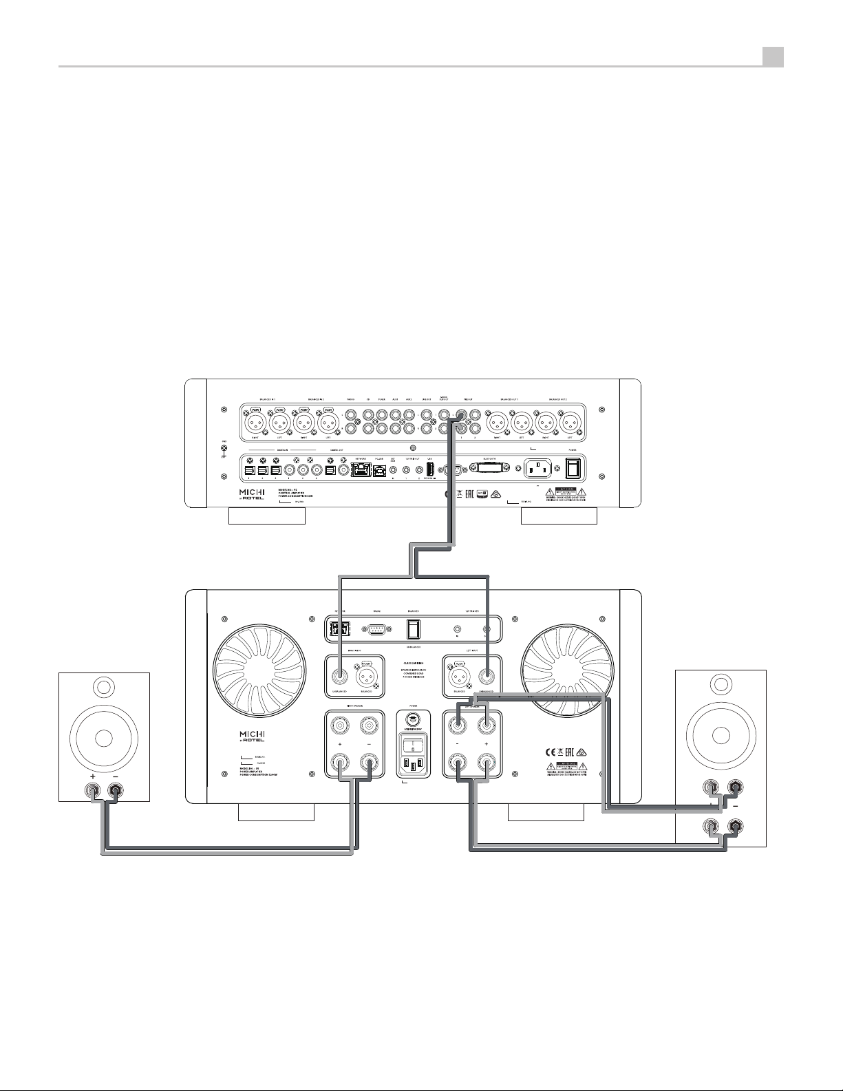
Figure 3 -1: Analog Input and Speaker Output Connections
Branchements des entrées analogiques et sorties enceintes acoustiques
Anschlussdiagramm (analoge Eingangsanschlüsse, Ausgangsanschlüsse für die
Lautsprecher)
Conexiones de Entrada Analógicas y de Salida a las Cajas Acústicas
Analoge ingangen en luidsprekeruitgangen
Collegamenti ingressi analogici ed uscite diffusori
Anslutningar för högtalare och analoga ingångar
Подсоединение источников сигнала на аналоговые входы и акустических систем

6S5 Stereo Power Amplifier /M8 Monoblock Power Amplifier
Figure 3-2 : Analog Input and Speaker Output Connections
Branchements des entrées analogiques et sorties enceintes acoustiques
Anschlussdiagramm (analoge Eingangsanschlüsse, Ausgangsanschlüsse für die
Lautsprecher)
Conexiones de Entrada Analógicas y de Salida a las Cajas Acústicas
Analoge ingangen en luidsprekeruitgangen
Collegamenti ingressi analogici ed uscite diffusori
Anslutningar för högtalare och analoga ingångar
Подсоединение источников сигнала на аналоговые входы и акустических систем
LF
HF
Michi M8
Michi P5
Speaker
Speaker
Michi M8
Single Wire Connection
Bi-wire Connection
7
Michi P5
Michi S5
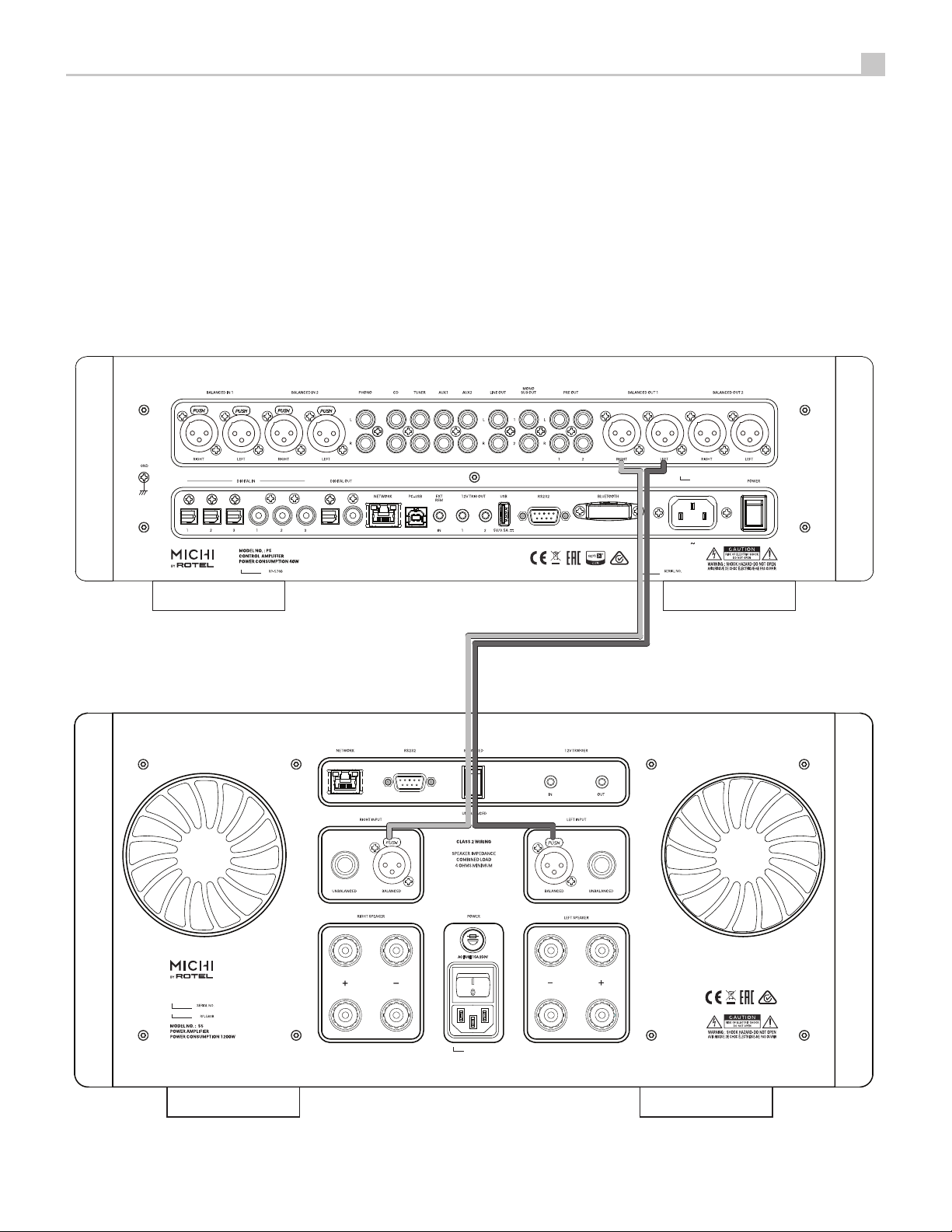
Figure 4-1 : Balanced (XLR) Inputs Connection
Entrées symétriques (XLR) connexion
Anschlussdiagramm (symmetrische (XLR-) Eingänge)
Conexión de Entradas Balanceadas (XLR)
Aansluiting Gebalanceerde ingangen (XLR)
Collegamenti ingressi bilanciati (XLR)
Balanserade anslutningar (XLR)
Балансные (XLR) Входы Подключение

8S5 Stereo Power Amplifier /M8 Monoblock Power Amplifier
Michi M8
Michi P5
Michi M8
Figure 4-2 : Balanced (XLR) Inputs Connection
Entrées symétriques (XLR) connexion
Anschlussdiagramm (symmetrische (XLR-) Eingänge)
Conexión de Entradas Balanceadas (XLR)
Aansluiting Gebalanceerde ingangen (XLR)
Collegamenti ingressi bilanciati (XLR)
Balanserade anslutningar (XLR)
Балансные (XLR) Входы Подключение

9
RP-565D
CLASS 1
LASER PRODUCT
APPAREIL LASER
DE CLASSE 1
Rotel RCD-1572
Michi S5
Michi P5
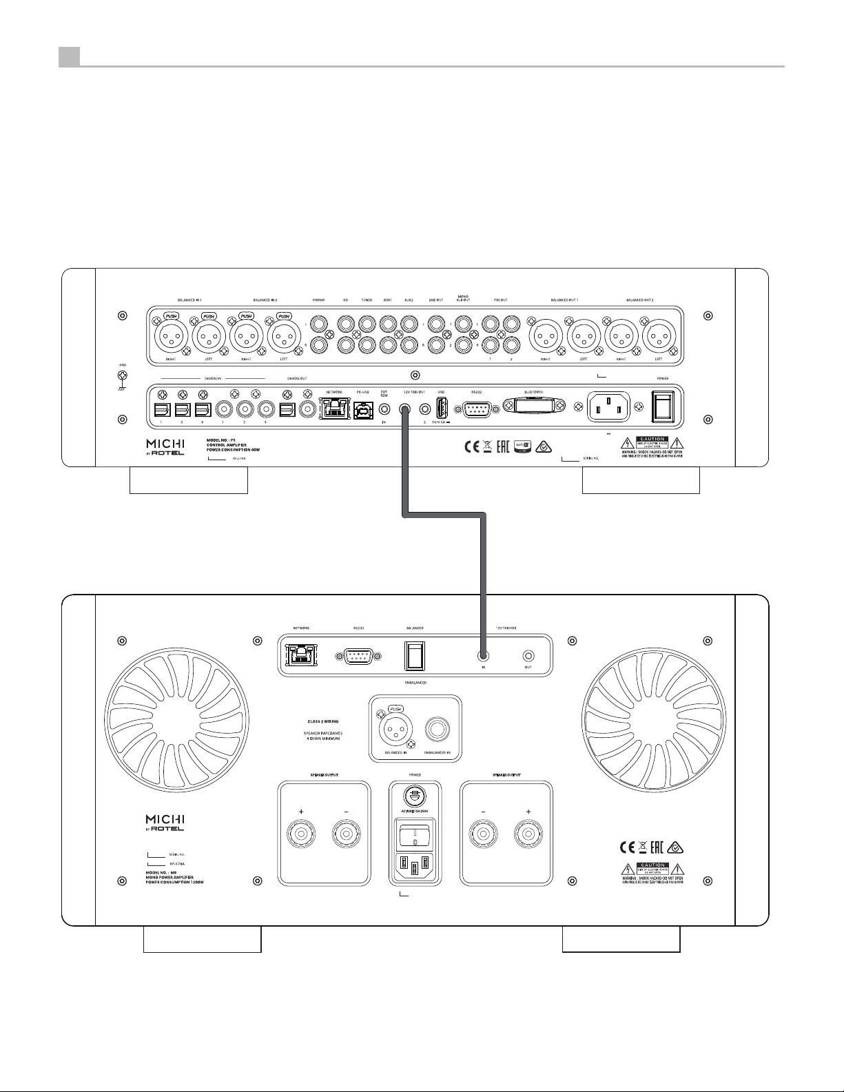
Figure 5-1 : 12V Trigger Connections
Branchements trigger 12 V
12V-Trigger-Anschlüsse
Conexiones para Señal de Disparo de 12V
De 12V trigger aansluitingen
Collegamenti segnali Trigger 12 V
12 V-anslutning för styrsignal
Подсоединение 12-В триггерного сигнала
10 S5 Stereo Power Amplifier /M8 Monoblock Power Amplifier
Michi M8
Michi P5
Figure 5-2 : 12V Trigger Connections
Branchements trigger 12 V
12V-Trigger-Anschlüsse
Conexiones para Señal de Disparo de 12V
De 12V trigger aansluitingen
Collegamenti segnali Trigger 12 V
12 V-anslutning för styrsignal
Подсоединение 12-В триггерного сигнала

11
Important Notes
When making connections be sure to:
Turn off all the components in the system before hooking up any components, including loudspeakers.
Turn off all components in the system before changing any of the connections to the system.
It is also recommended that you:
Turn the volume control of the amplifier all the way down before the amplifier is turned on or off.
Remarques importantes
Pendant les branchements, assurez-vous que :
Tous les maillons sont éteints avant leur branchement, quels qu’ils soient, y compris les enceintes acoustiques.
Éteignez tous les maillons avant de modifier quoi que ce soit au niveau de leurs branchements, quels qu’ils soient.
Il est également recommandé de :
Toujours baissez le niveau sonore via le contrôle de volume, avant d’allumer ou d’éteindre l’amplificateur.
Wichtige Hinweise
Achten Sie beim Herstellen der Verbindungen auf Folgendes:
Schalten Sie alle Komponenten im System ab, bevor Sie Geräte (einschließlich Lautsprecher) anschließen.
Schalten Sie alle Komponenten im System ab, bevor Sie Anschlüsse im System verändern.
Ferner empfehlen wir, dass
Sie die Lautstärke herunterdrehen, bevor Sie den Verstärker ein- oder abschalten.
Notas Importantes
Cuando realice las conexiones, asegúrese de que:
Desactiva todos los componentes del equipo, cajas acústicas incluidas, antes de conectar cualquier nuevo componente en el mismo.
Desactiva todos los componentes del equipo antes de cambiar cualquier conexión del mismo.
También le recomendamos que:
Reduzca el nivel de volumen de su amplificador a cero antes de activarlo o desactivarlo.
Héél belangrijk
Bij het maken van de verbindingen:
Zorg dat niet alleen de S5 / M8, maar de gehele installatie uitstaat, als nog niet alle verbindingen gemaakt zijn.
Zorg dat niet alleen de S5 / M8, maar de gehele installatie ook uitstaat, als u verbindingen gaat wijzigen.
Wij raden u ook aan om
de volumeregelaar van de (voor)versterker geheel dicht te draaien (volkomen linksom) wanneer u uw eindversterker aan- of uitzet.
Note importanti
Quando effettuate i collegamenti assicuratevi di:
Spegnere tutti i componenti del sistema prima di collegare qualsiasi componente, inclusi i diffusori.
Spegnere tutti i componenti del sistema prima di modificare qualsiasi connessione nel sistema.
Vi raccomandiamo inoltre di:
Portare il volume a zero prima di accendere o spegnere l’amplificatore.
Viktigt
Tänk på följande när du gör anslutningar:
Stäng av alla apparater i anläggningen innan du ansluter nya komponenter eller högtalare.
Stäng av alla apparater i anläggningen innan du ändrar någon anslutning.
Du rekommenderas också:
Vrida ner volymen på förförstärkaren helt och hållet innan förstärkaren slås på eller av.
LJÊÌ˚ Á‡Ï˜‡ÌËfl
è‰ ÔÓ‰ÒÓ‰ËÌÂÌËÂÏ:
Ç˚Íβ˜ËÚ ‚Ò ÍÓÏÔÓÌÂÌÚ˚, ‚Íβ˜‡fl ÍÓÎÓÌÍË.
Ç˚Íβ˜ËÚ ‚Ò ÍÓÏÔÓÌÂÌÚ˚ ‚ ‚‡¯ÂÈ ÒËÒÚÂÏÂ, ÔÂʉ ˜ÂÏ ˜ÚÓ-ÚÓ ‚ ÌÂÈ ÏÂÌflÚ¸.
êÂÍÓÏẨÛÂÚÒfl Ú‡ÍÊÂ:
Ç˚‚ÂÒÚË „ÓÏÍÓÒÚ¸ ÛÒËÎËÚÂÎfl ̇ ÏËÌËÏÛÏ, Ô‰ ÚÂÏ Í‡Í ‚Íβ˜‡Ú¸ ËÎË ‚˚Íβ˜‡Ú¸ „Ó.

12 S5 Stereo Power Amplifier /M8 Monoblock Power Amplifier
A Word About Watts
The S5 power output is rated as 500 watts for each channel, when both
channels are operating together at full power at across a full 20 Hz to 20K
Hz. And the M8 power output is rated as 1080 watts in 8 ohms load when it
isoperatingat fullpower.Michi haschosen to specifythe poweroutput in this
way because, in our experience, it gives the most true value of the receiver or
amplifier’s power capability.
Whencomparingperformance and specificationsfordifferentproducts,you
should be aware that power output is often specified in other ways so you
may not be comparing like with like. For example, the power output may be
quoted with only one channel operating at a much higher distortion output
or a single, ideal frequency, giving a higher maximum power output figure.
Aloudspeaker’s impedanceratingindicatesthe electrical resistance or loadit
offers when connected to the amplifier, usually 8 ohms or 4 ohms. The lower
the impedance, the more power the speaker will need. In effect, a 4 ohm
speaker will require twice as much power as an 8 ohm speaker.
However, Michi amplifiers are designed to work into any speaker impedance
between8and4 ohms,and withall thechannels workingup totheir fullpower.
Because Michi designs are optimized for use with all channels operating
together, Michi is able to specify the true power output for both channels.
This architecture, design and performance rating is sure to please both the
speakers and audience when enjoying music of any genre or listening level.
Getting Started
Thank you for purchasing the Michi S5 Stereo Power Amplifier or Michi M8
MonoblockPowerAmplifier.When usedina high-quality musicaudio system,
your Michi product will provide years of musical enjoyment.
The S5 and M8 are high-power professional amplifiers, providing the highest
level of audio performance. A massive power supply, premium components,
and Michi’s design architecture ensure superb sound quality. High current
capability of this power supply allows the S5 and M8 to drive the most
demanding loudspeakers.
Beawarethatthe S5and M8arecapableof highpowerlevels,in excess of500
wattsand1080 wattsrespectivelyperchannel. Makesurethatyour speakers
can handle the power of the amplifier. If in doubt about your speakers, ask
your local Michi audio dealer for advice.
This amplifier is straightforward in its installation and operation. If you have
experiencewithotherpoweramplifiers,youshouldn’tfindanythingperplexing.
Simply plug in the associated components and enjoy.
A Few Precautions
WARNING: To avoid potential damage to your system, turn off ALL
the components in the system when connecting or disconnecting the
loudspeakers or any associated components. Do not turn the system
components back on until you are sure all the connections are correct
and secure. Pay particular attention to the speaker wires. There must
be no loose strands that could contact the other speaker wires, or the
chassis of the amplifier.
Contents
Important Safety Instructions . . . . . . . . . . . . . . . . . . . . . . . . . . . . . . . . . . . 2
Figure 1: Controls and Connections 3
Figure 2: RR-RH6 Remote Control 4
Figure 3-1: Analog Inputs and Speaker Output Connections 5
Figure 3-2: Analog Inputs and Speaker Output Connections 6
Figure 4-1: Balanced (XLR) Inputs Connections 7
Figure 4-2: Balanced (XLR) Inputs Connections 8
Figure 5-1: 12V Trigger Connections 9
Figure 5-2: 12V Trigger Connections 10
Important notes 11
A Word About Watts . . . . . . . . . . . . . . . . . . . . . . . . . . . . . . . . . . . . . . . . . . .12
Getting Started . . . . . . . . . . . . . . . . . . . . . . . . . . . . . . . . . . . . . . . . . . . . . . .13
A Few Precautions 13
Placement 13
Cables 13
The RR-RH6 Remote Control . . . . . . . . . . . . . . . . . . . . . . . . . . . . . . . . . . .13
Remote Control Batteries 13
AC Power and Control . . . . . . . . . . . . . . . . . . . . . . . . . . . . . . . . . . . . . . . . .14
AC Power Input -14
Master Power Switch -14
12V TRIGGER Connection 914
Protection Circuitry 214
Input Signal Connections . . . . . . . . . . . . . . . . . . . . . . . . . . . . . . . . . . . . . .14
Input Selector Switch 814
Speaker Outputs . . . . . . . . . . . . . . . . . . . . . . . . . . . . . . . . . . . . . . . . . . . . .14
Speaker Selection 14
Speaker Wire Selection 14
Polarity and Phasing 15
Speaker Connections 0= 15
Cooling Fans 4. . . . . . . . . . . . . . . . . . . . . . . . . . . . . . . . . . . . . . . . . . . . . . .15
RS232 7. . . . . . . . . . . . . . . . . . . . . . . . . . . . . . . . . . . . . . . . . . . . . . . . . . . . .15
Network Connection 6. . . . . . . . . . . . . . . . . . . . . . . . . . . . . . . . . . . . . . . .15
Setup Menu . . . . . . . . . . . . . . . . . . . . . . . . . . . . . . . . . . . . . . . . . . . . . . . . . .15
Front Panel Overview . . . . . . . . . . . . . . . . . . . . . . . . . . . . . . . . . . . . . . . . . .15
Remote Sensor 315
Display 115
Overview of Buttons and Controls. . . . . . . . . . . . . . . . . . . . . . . . . . . . . . .15
Main Menu . . . . . . . . . . . . . . . . . . . . . . . . . . . . . . . . . . . . . . . . . . . . . . . . . . .16
Network Configuration 16
Display Configuration 17
System Configuration 17
Troubleshooting . . . . . . . . . . . . . . . . . . . . . . . . . . . . . . . . . . . . . . . . . . . . . .17
Power Indicator Is Not Illuminated 17
Fuse Replacement 17
No Sound 17
Protection Indicator 17
Specifications . . . . . . . . . . . . . . . . . . . . . . . . . . . . . . . . . . . . . . . . . . . . . . . .18

13
Pleasereadthis manualcarefully.Inaddition tobasicinstallationandoperating
instructions,itprovidesvaluableinformationonvarioussystemconfigurations
as well as general information that will help you get optimum performance
from your system. Please contact your authorized Michi dealer for answers
to any questions you might have. In addition, all of us at Michi welcome your
questions and comments.
Save the shipping carton and all enclosed packing material for future use.
Shipping or moving the amplifier in anything other than the original packing
material may result in severe damage to your audio components.
Ifincluded in theboxplease completethe owner’s registration cardor register
online. Also be sure to keep the original sales receipt. It is your best record
of the date of purchase, which you will need in the event warranty service
is ever required.
Placement
The S5 and M8 generate heat as part of its normal operation. The heatsinks
and ventilation openings in the amplifier are designed to dissipate this heat.
There should be 50 cm (20 inches) of clearance around the chassis and
reasonable airflow through the installation location to prevent the amplifier
from overheating.
Remembertheweightof theamplifier whenyouselectaninstallationlocation.
Makesurethattheshelfor cabinetcan supportit. We recommendinstallingthe
S5and M8 on furnituredesignedto house audiocomponents. Suchfurniture
isdesigned to reduceor suppressvibrationwhich canadverselyaffectsound
quality.Ask yourauthorizedMichi dealerforadvice aboutcomponentfurniture
and proper installation of audio components.
The S5 and M8 are supplied with an RR-RH6 remote control and must be
placed where the infrared signal from the remote can reach the front panel
Remote Sensor.
Cables
Besuretokeep the powercords,digital signal cables andanalogaudio signal
cablesin yourinstallationaway fromeach other.This willminimizethe chance
of the analog audio signal cables picking up noise or interference from the
power cords or digital cables. Using only high quality, shielded cables will
also help to prevent noise or interference from degrading the sound quality
of your system. If you have any questions see your authorized Michi dealer
for advice about the best cable to use with your system.
The RR-RH6 Remote Control
Operations with the remote control are described in this manual showing the
function keys with encircled letters.
Remote Control Batteries
Two AAA size batteries must be installed before the remote control can be
used. To install the batteries, follow the steps as below:
1. Lift the ribbon under the remote control and remove it out of the box.
Remote Control
Battery
(if included)
Hex Tool
USB Flash Drive
2. Remove the screw on the back of the remote using the hex tool provided
with the remote. Use only the hex tool supplied to avoid damaging the
attaching screw.
3. Install the batteries as shown in the illustration in the battery well (Figure
2).Please notetherearenegativeand positivemarksshown on thebattery
cover(Figure1). Reassemblethe batterycoverand tightenthe screwthen
test the control for proper operation.
Figure 1 Figure 2
Whenthe batteriesbecomeweaktheremotecontrolwon’toperate thedevice
consistently. Installing fresh batteries should eliminate the problem.
NOTE: Use only the tool supplied with the unit to remove the screw to
avoid damage to the hex screw.
NOTE: Do NOT over-tighten the screw to avoid damage to the screw or
remote control.
AC Power and Control
AC Power Input -
Youramplifier is configuredatthe factoryforthe properAC linevoltage in the
country where you purchased it (either 120 volts AC or 230 volts AC with a
line frequency of either 50 Hz or 60 Hz). The AC line configuration is noted
on a decal on the back panel.
NOTE: Should you move your amplifier to another country, it is possible
to reconfigure your amplifier for use on a different line voltage. Do not
attempt to perform this conversion yourself. Opening the enclosure of
the amplifier exposes you to dangerous voltages. Consult a qualified
service person or the Michi factory service department for information.
NOTE: Some products are intended for sale in more than one country
and as such are supplied with more than one AC cord. Please only use
the one appropriate for your country/region.
Becauseofits relativelyhigh powerrating,the amplifiercan draw considerable
current.Therefore,it shouldbepluggeddirectlyintoapolarized walloutletusing
the supplied cable or other high current compatible cable as recommended
by your authorized Michi dealer. Do not use an extension cord.
If you are going to be away from home for an extended period of time such as
amonth-long vacation,it isa sensible precautiontounplug youramplifier(as
well as other audio and video components) while you are away.

14 S5 Stereo Power Amplifier /M8 Monoblock Power Amplifier
Master Power Switch -
The large rocker switch on the rear panel is a master power switch. When it is
in the OFF position, power to the unit is completely off. When it is in the ON
position,the frontpanelPower2buttonandremotecontrolPowerAbutton
can be used to activate the unit or put it into standby mode.
12V TRIGGER Connection 9
See Figures 5-1/5-2
The jack labeled IN is for connecting the 3.5 mm Plug/Cable carrying a +12
volt trigger signal to turn the amplifier on and off. This input accepts any
control signal (AC or DC) ranging from 3 volts to 30 volts.
Thejack labeled OUT isforconnecting another 3.5 mmplug/cabletoprovide
a 12V trigger signal to other components. The 12V output signal is available
whenever a +12 volt trigger signal is applied to the IN connector.
Protection Circuitry 2
The amplifier features thermal and over-current protection circuits that
protect against potential damage in the event of extreme or faulty operating
conditions. Unlike many designs, these protection circuits are independent
of the audio signal and have no impact on sonic performance. Instead, the
protection circuits monitors the temperature of the output devices and the
currenttheyarehandling andshuts downthe amplifierif operatingconditions
exceed safe limits.
Most likely, you will never see this protection circuitry in action. However,
should a faulty condition arise, the amplifier will stop playing and the Power
LED on the front panel will be red.
If this happens, turn the amplifier off, let it cool down for several minutes, and
attempttoidentifyand correctthe problem.When youturntheamplifier back
on, the protection circuit will automatically reset and the Power LED should
be white, indicating that the amplifier is operating normally.
Inmostcases,theprotectioncircuitryactivatesbecauseofafaultconditionsuch
asshortedspeakerwires, orinadequateventilationleading toan overheating
condition. In very rare cases, highly reactive or extremely low impedance
speaker loads could cause the protection circuit to engage.
If the protection circuitry triggers repeatedly and you are unable to isolate
and correct the faulty condition, contact your authorized Michi dealer for
assistance in troubleshooting.
Input Signal Connections
See Figure 3-1/3-2
NOTE: To prevent loud noises that neither you nor your speakers will
appreciate, makesurethesystemisturnedoffwhen you makeany signal
connections.
TheS5 and M8haveconventionalRCA typeinput connectors,the typefound
on nearly all audio equipment, as well as Balanced (XLR) input connectors.
Selecthighqualityaudiointerconnectcables.Connecteachoftheoutputsfrom
thepreamplifieror signalprocessortothecorrespondinginputoftheamplifier.
Input Selector Switch 8
Atoggle switchin therearpanelselectsthe type ofinputsignal touse.Select
the correct inputs to use with this switch.
NOTE: You should choose only one method of analog connection from
a source component to the amplifier. Do not connect both the RCA and
XLR outputs of a source component to the amplifier at the same time.
Speaker Outputs
See Figures 3-1/3-2
Speaker Selection
We recommend using loudspeakers with a nominal impedance of 4 ohms or
higher with the amplifier. The dual output binding posts are ideal for bi-wire
installations allowing 2 pairs of wires to drive the HF and LF speakers each
with individual wires from the left or right channel of the amplifier. Speaker
impedance ratings are less than precise so use care when selecting the
loudspeakers to attach to the amplifier. In practice, very few loudspeakers
will present any problems for the amplifier. See your authorized Michi dealer
if you have any questions.
Speaker Wire Selection
Use insulated two-conductor stranded wire to connect the amplifier to the
speakers. The size and quality of the wire can have an audible effect on the
performance of the system. Standard speaker wire will work, but can result in
loweroutput ordiminished bass response,particularly overlonger distances.
Ingeneral,heavierwirewill improvethesound. Forbestperformance,youmay
want to consider special high-quality speaker cables. Your authorized Michi
dealer can help in the selection of cables for your system.
Polarity and Phasing
Thepolarity – the positive/negativeorientationof the connections– forevery
speaker and amplifier connection must be consistent so all the speakers will
be in phase. If the polarity of one connection is reversed, bass output will be
veryweakandstereoimagingdegraded. Allwire ismarkedso youcanidentify
the two conductors. There may be ribs or a stripe on the insulation of one
conductor.The wiremayhaveclear insulationwith different colorconductors
(copperand silver).Theremaybepolarity indicationsprintedonthe insulation.
Identify the positive and negative conductors and be consistent with every
speaker and amplifier connection.
Speaker Connections 0=
NOTE: The following text describes both binding post and plug-in
connections. DO NOT use both connection methods in combination to
connect multiple speakers.
Turnoff allthe componentsinthesystem before connectingthe speakers.The
amplifier has color-coded binding post connectors on the back panel. These
connectorsacceptbarewire,connectorlugs, ordual bananatype connectors.
(Exceptin EuropeanCommunity countrieswhere theiruse is not permitted.)
Route the wire from the amplifier to the speakers. Give yourself enough slack
so you can move the components to allow access to the speaker connectors.
If you are using dual banana plugs, connect them to the wires and then plug
into the backs of the binding posts. The thumbscrews of the binding posts
should be screwed in all the way (clockwise).
If you are using terminal lugs, connect them to the wires. If you are attaching
bare wires directly to the binding posts, separate the wire conductors and
strip the insulation from the end of each conductor. Be careful not to cut into
the wire strands. Unscrew (turn counterclockwise) the binding post. Place

15
the connector lug or wire around the binding post shaft or threaded through
the hole in the binding post. Turn the binding post clockwise to clamp the
connector lug or wire firmly in place.
NOTE: Be sure there are no loose wire strands that could touch adjacent
wires or connectors.
Cooling Fans 4
The Michi S5 / M8 is equipped with dual cooling fans to help ventilate the
internal components. It will adjust the fan speed automatically depending
on the temperature of the unit.
NOTE: The amplifier produces significant power and associated heat -
evenwith the cooling fansin use. Appropriateinstallationand ventilation
is required to ensure proper operation.
RS232 7
The S5 / M8 can be controlled via RS232 for integration with automation
systems.TheRS232input acceptsastandardstraightDB-9 Male-to-Female
cable.
Foradditional information on theconnections, software, and operatingcodes
for RS232 control of the amplifier, contact your authorized Michi dealer.
Network Connection 6
The S5/ M8 can be attached to a network using the rear panel NETWORK
socket 6. The NETWORK configurations allow both STATIC and DHCP IP
addressing. See the Network section of this manual under Setting Menu for
IP address configuration information.
The NETWORK connection allows software updates to be downloaded from
the Internet. The NETWORK connection also allows IP control for integration
with automation systems.
For additional information on the IP control please contact your authorized
Michi dealer.
Setup Menu
The Michi S5 / M8 features a front panel display to show information and
status. A more comprehensive ON-SCREEN DISPLAY (OSD) menu system is
availableatanytimeby pressingthe SETUPbutton onthe remote.TheseOSD
menus guide you through the configuration and setup of the amplifier. The
settingsmade intheconfigurationprocessarememorized asdefaultsettings
and need not be made again for normal operation of the unit.
Front Panel Overview
The following is a brief overview of the controls and features on the front
panel of the unit.
Remote Sensor 3
This remote sensor window receives IR commands from the remote control.
Please do not block this sensor.
Display 1
Thefrontpaneldisplayshowsthe currentamplifier status.The displayprovides
access to the setup and configuration menu options of the amplifier.
Overview of Buttons and
Controls
Thissectionprovidesabasicoverview ofthebuttonsand controlsontheremote
control. Detailed instructions on the use of these buttons are provided in the
more complete operating instructions in the following sections.
Navigating Dand Enter KButtons : Usethe navigationbuttons/ D
and the Enter button Kon the remote control to access the various menus.
Power 2A:ThePowerbuttonon the frontpanel andon the remotecontrol
activate or deactivate the unit.There isan LED lightin themiddle of thePower
button on the remote control, which will be illuminated when you pick up the
remote control. To power on the unit, the rear panel master POWER switch
must be in the ON position for the front panel Power and the remote standby
function to operate.
Power On - To power on the unit press and release the power button 2on
the front panel or remote control A.
Power Off / Standby - To power off the unit to standby push and release the
power button 2on the front panel or PUSH-HOLD the the remote control
power button Afor 1.5 seconds.
NOTE All Michi products will respond to the same Power On and Off
commands to simplify the power control when multiple products are
installed. To controlthe powerusing the IR remotefollowthe instructions
above and point the remote control at the Michi products. If a unit does
notrespondtoapoweronor off fromthe IR remotesimply PUSH orPUSH
HOLD the power button again to resend the desired command.
SETUP B:The SETUP button activates the OSD setup screen on the front
display. Push the SETUP button again to move to the previous setup menu as
a “back” button or exit setup menu if on the first level of setup menu.
SOURCE C:This function is not used on the S5 and M8.
DISPLAY G:Dims the front display. To dim the display PUSH-HOLD the
DISPLAY Gbutton on the remote control for 3 seconds. To turn on the
display to the level of brightness configured in the setup menu PUSH and
release the DISPLAY Gbutton.
NOTE The DISPLAY button is common for all Michi models. To Dim or
enablethedisplayPUSHorPUSH-HOLD the buttonandpointtotheMichi
products. If a unit does not respond to a DISPLAY command simply send
the command again using a PUSH or PUSH-HOLD.
AUDIO H:This function is not used on the S5 and M8.
ButtonE:This function is not used on the S5 and M8. However MUTE
will toggle the MUTE function on the Michi P5 Preamplifier.

16 S5 Stereo Power Amplifier /M8 Monoblock Power Amplifier
VOLUME +/- Buttons F: This function is not used on the S5 and M8. This
function is used on the Michi P5 to increase or decrease the volume of the
Preamplifier. Push or push/hold the button to change the volume.
Main Menu
NETWORK
SETUP
DISPLAY
SYSTEM
Exit
The Setup menu provides access to OSD screens for various configuration
options. Setup menu is reached by pressing the SETUP Bbutton on the
remote. To select the desired menu, move the highlight using the / D
arrowbuttonsand pressthe EnterKbutton on theremotecontrol.Pressthe
SETUP Bbuttonagain toreturntothe previousmenu orselect “EXIT“ onthe
OSD to end setup and return to normal operation.
Network Setup
Stativ IP
Disabled
DHCP
NETWORK
SETUP
Status
Renew IP Address
Network Standby
IP Address
Subnet Mask
Network Type
ThisNetworkmenuin theSetup menu,providesthefollowingoptions,selected
by placing the highlight on the desired line using the / Darrow buttons
and pressing the Enter Kbutton. This action displays the right side options
allowingchanges. Change theoptions using the/ Darrow buttonsand
press the Enter Kbutton to confirm.
Status: Ifthenetwork isproperlyconfiguredand attachedtothe networkthen
“Connected”will be displayed.Ifthe networkisnot properlyconfiguredor not
connected to a network, “Disconnected“ will be displayed.
Network Type: In most systems, set the IP ADDRESS MODE to DHCP.
This setting will allow your router to assign an IP address to the amplifier
automatically. If your network uses fixed IP addresses, set the IP ADDRESS
MODE to Static. To disable the IP connection set this option to DISABLED.
Options include: DHCP (Default), Static IP, Disabled.
Renew IP Address: Disabled if NetworkType isStatic orDisabled.If Network
Type is DHCP then select Yes and press the Enter Kbutton to renew the IP
address.
Network Standby: When set to ENABLED the amplifier will maintain the
EthernetIP connection eveninStandby Modeallowingtheunit tobe powered
onvia IP.IfDisabled the unitwill notpoweron fromthe IPconnection and must
use either the front panel, IR remote or RS232 to power on the unit.
Options Include: Disabled (Default), Enabled.
NOTE WhenNetworkStandbyis set to ENABLED the unit mayconsume
more power in standby mode.
IPAddress/SubnetMask/Gateway/DNS: DisabledifNetworkTypeis DHCP
orDisabled.If STATICmode isselected youmustconfigureallsettings forthe
network including IP Address, Subnet Mask, Gateway and DNS Server. Press
the Enter Kbutton to activates the first digit in the line you want to change,
then use the / Darrow buttons to adjust the values and press the Enter
Kto cycle to the next digit. When the proper IP information is configured
press the Enter Kbutton to move the cursor back to the previous menu and
accept the settings. After entering the STATIC IP address information the
network will be tested and connection status reported.
NOTE: For more information regarding network connection please
contact your authorized Michi dealer.
NOTE: A network connection is not required for the amplifier to operate.
Press the SETUP Bbutton on the remote control to exit the setup menu or
select “Back” on the OSD to return to the main menu.
Display Configuration
Medium High
DISPLAY
SETUP
Function
Brightness High
LED Brightness Medium
Back Medium Low
Low
ThisDisplaymenu inthe Setupmenu, providesthe followingoptions, selected
by placing the highlight on the desired line using the / Darrow buttons
and pressing the Enter Kbutton. This action displays the right side options
allowingchanges. Change theoptions using the/ Darrow buttonsand
press the Enter Kbutton to confirm.
Brightness: Thisfunctionsets the brightnessof thefrontdisplay. The setting
is activated during normal operation by a push release of the DISPLAY button
Gonthe remotecontrol.TheOSD will always activateatthe mostbrightlevel
regardless of the Brightness setting to ensure the unit configuration options
can easily be accessed and modified.
Options includes: High (Default), Medium High, Medium, Medium Low, Low.
NOTE To dim the front display PUSH-HOLD the DISPLAY
G
button on
the remote control for 3 seconds.

17
Troubleshooting
Most difficulties in audio systems are the result of incorrect connections, or
improper control settings. If you encounter problems, isolate the area of the
difficulty, check the control settings, determine the cause of the fault and
makethenecessary changes.If youareunable togetsound fromtheamplifier,
refer to the suggestions for the following conditions:
Power Indicator Is Not Illuminated
Thefrontpowerindication willbe illuminatedanytimethe unitis connectedto
AC power and the rear power switch is set to the ON position. The indication
willbe RED forstandbymodeandWHITE in normaloperation.If theindication
is not illuminated, test the power outlet with another electrical device, such
as a lamp. Be sure the power outlet being used is not controlled by a switch
that has been turned off. And check all AC power including the rear power
switch to ensure the unit is receiving power.
Fuse Replacement
Ifanother electrical deviceworkswhen pluggedinto thepoweroutlet, but the
Power Indicatorstillwill not illuminatedwhen theamplifier is pluggedintothe
walloutlet, itindicatesthat thepower fusemayhaveblown. Ifyou believethis
hashappened, contactyour authorizedMichi dealer toget thefuse replaced.
No Sound
If the amplifier is getting AC power, but is producing no sound, check the rear
panel BALANCED / UNBALANCED switch to ensure this is set to the proper
position matched with the analog source input. Also check if the speaker
cables are securely attached and the unit is not displaying a PROTECTION
message on the front panel TFT display.
Protection Indicator
Thefront panel POWER indicatoris redwhen theamplifierprotectioncircuits
have shut off the amplifier. Typically, this occurs only when the ventilation
openings are blocked, when there is faulty speaker wiring, or after a period
of extreme use. Turn off the system and wait for the amp to cool. Then push
the front panel power switch in and out to reset the protection devices. If the
problem is not corrected or reoccurs, there is a problem with the system or
the amplifier itself.
Function: The amplifier can be configured to display the input audio source
as either a dB Peak Power Meter or a Frequency Spectrum Analyzer. The
display can also be configured as OFF during normal operation. Select the
desired setting using the / Darrow buttons and press the Enter K
button to comfirm.
Options includes: VU Meter, Spectrum 8, Spectrum 12 (Default), Spectrum
16, OFF.
LEDBrightness:SetsthebrightnessoftheONlevelofthefrontpanelPowerLED.
Options include: High (Default), Medium High, Medium, Medium Low, Low.
Press the SETUP Bbutton on the remote control to exit the setup menu or
select “Back” on the OSD to return to the main menu.
System Configuration
USB
Internet
SYSTEM
SETUP
Software Version
Factory Default
Back
Software Update No
ThisSystemmenuin theSetup menu,providesthefollowingoptions,selected
by placing the highlight on the desired line using the / Darrow buttons
and pressing the Enter Kbutton. This action displays the right side options
allowingchanges. Change theoptions using the/ Darrow buttonsand
press the Enter Kbutton to confirm.
SoftwareVersion:Thisshowsthecurrentsoftware versionloadedintotheunit.
Software Update: Select the desired update method to update the unit.
Options includes: No (Default), USB, Internet.
Factory Default: Thisoptionsets the unitback tothe original settingas when
it left the factory. All user settings will be erased.
NOTE Use caution when resetting the amplifier to factory defaults as
all user configured options will be erased and reset to original factory
settings.
Press the SETUP Bbutton on the remote control to exit the setup menu or
select “Back” on the OSD to return to the main menu.

18 S5 Stereo Power Amplifier /M8 Monoblock Power Amplifier
Specifications
S5
S5
Continuous Power Output
Continuous Power Output 500 watts/channel (8 ohms)
800 watts/channel (4 ohms)
Total Harmonic Distortion
Total Harmonic Distortion < 0.008%
Intermodulation Distortion
Intermodulation Distortion < 0.03%
(60 Hz : 7kHz, 4:1)
Frequency Response
Frequency Response 20 Hz - 20k Hz (+ 0 dB, - 0.15 dB)
10Hz - 100k Hz (+ 0 dB, - 0.4 dB)
Damping Factor
Damping Factor
(1kHz, 8 ohms)
350
Input Sensitivity / Impedance
Input Sensitivity / Impedance
Unbalance 2.6 V / 12.5k ohms
Balance 4.2 V / 100k ohms
Gain
Gain
Unbalance 28 dB
Balance 24 dB
Signal to Noise Ratio
Signal to Noise Ratio (IHF “A” weighted) 120 dB
Crosstalk / Separation
Crosstalk / Separation >65 dB
Power Requirements:
Power Requirements:
USA: 120 volts, 60 Hz
EC: 230 volts, 50 Hz
Power Consumption
Power Consumption 1200 watts
Standby
Standby
Normal < 0.5 watts
Network Wakeup < 2 watts
BTU
BTU
(4 ohms, 1/8th power)
3450 BTU/h
Dimensions
Dimensions
(W x H x D)
485 x 238 x 465 mm
(19 x 9 3/8x 18 1/4ins.)
Front Panel Height
Front Panel Height 220 mm, 8 3/4ins.
Weight
Weight
(net)
59.9 kg, 132.1 lbs.
All specifications are accurate at the time of printing.
M8
M8
Continuous Power Output
Continuous Power Output l
1080 watts/channel (8 ohms)
1800 watts/channel (4 ohms)
Total Harmonic Distortion
Total Harmonic Distortion < 0.018%
Intermodulation Distortion
Intermodulation Distortion < 0.03%
(60 Hz : 7kHz, 4:1)
Frequency Response
Frequency Response 20 Hz - 20k Hz (+ 0 dB, - 0.15 dB)
10Hz - 100k Hz (+ 0 dB, - 0.5 dB)
Damping Factor
Damping Factor
(1kHz, 8 ohms)
200
Input Sensitivity / Impedance
Input Sensitivity / Impedance
Unbalance 1.85 V / 12.5k ohms
Balance 3 V / 100k ohms
Gain
Gain
Unbalance 34 dB
Balance 30 dB
Power Requirements:
Power Requirements:
USA: 120 volts, 60 Hz
EC: 230 volts, 50 Hz
Power Consumption
Power Consumption 1200 watts
Standby Power Consumption
Standby Power Consumption
Normal: < 0.5 watts
Network Wakeup: < 2 watts
BTU
BTU (4 ohms, 1/8th power) 3200 BTU/h
Dimensions
Dimensions
(W x H x D)
485 x 238 x 465 mm
(19 x 9 3/8x 18 1/4ins.)
Front Panel Height
Front Panel Height 220 mm, 8 3/4ins.
Weight
Weight (net) 59.1 kg, 130.3 lbs.
Michi reserves the right to make improvements without notice.

S5 / M8 Owner’s Manual Ver J 120919 English
Rotel Global Ofce
Room 1903, 19/F., Dominion Center
43-59 Queen’s Road East Wanchai
Hong Kong
Tel: 852 2793 9378
Fax: 852 3583 5035
Rotel of America
54 Concord Street
North Reading, MA 01864-2699
USA
Phone: +1 978-664-3820
Fax: +1 978-664-4109
Rotel Canada
Kevro International
902 McKay Rd. Suite 4
Pickering, ON L1W 3X8
Canada
Tel: +1 905-428-2800
Rotel Europe
Dale Road
Worthing, West Sussex BN11 2BH
England
Phone: + 44 (0)1903 221 763
Fax: +44 (0)1903 221 525
Rotel Deutschland
Vertrieb: B&W Group Germany GmbH
Kleine Heide 12
D-33790 Halle/Westf., Deutschland
Tel.: 05201 / 87170
Fax: 05201 / 73370
E-Mail: [email protected]
www.michi-hi.com
This manual suits for next models
1
Table of contents
Other Michi Amplifier manuals


