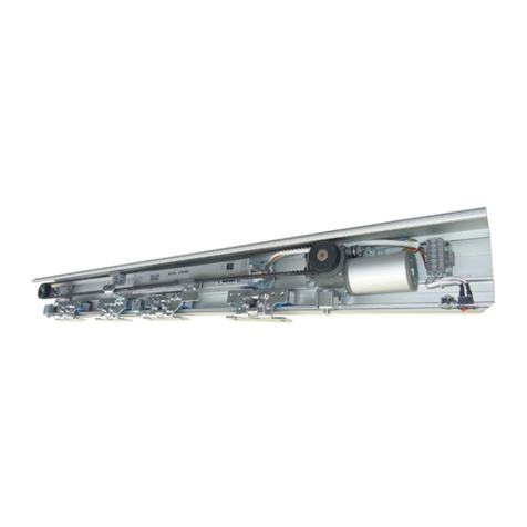
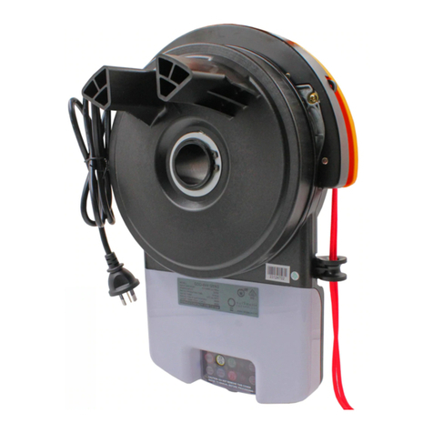
Micom Autodoor EDM NII Series User manual

EDM NII Series
Control Manual
MICOM AUTODOOR
Automatic Sliding Door Operator
Model: EDM NII Series
(Effective from Lot No. 1206)
Original Instructions
OPERATION MANUAL
(Date: June 2012)
OSAKA –JAPAN
www.micomautodoor.com

EDM NII Series
Control Manual
IMPORTANT NOTICE
Please read these instructions carefully before installing the door operator. We are not
responsible for any loss or damage if these precautions are not followed. The device must be
installed correctly according to the installation and wiring instructions.
During maintenance and installation, the power should be turned OFF.
Please use the correct power supply. Control box accepts 100VAC only.
(Do not connect 220-240VAC directly)
Make sure that the operator is grounded or connected to earth! The coating of the operator is
made of an electrically conductive metallic material, which will easily induce electrical conduction!
Make sure the ground or earth wire is connected!
The operator housing is not completely sealed, therefore it should be noted that excessive
moisture or a corrosive atmosphere could destroy the electronic components contained within.
Do not attempt to modify, repair, or alter any parts within the control box. Do not remove screws
and bolts from the internal structure of the Control Unit. The failure to comply will result in loss of
warranty.
Installation and maintenance of this product can be performed by MICOM authorized technician or
personnel only.
Before switching ON the power supply, make sure that no objects obstruct the travel of the
automatic doors.
Ensure door travel area is clear before switching power switch ON. Failure to comply may cause
incorrect operation.
Do not switch off power supply whilst door(s) is in motion. Failure to comply could result in death
or serious injury.
Take special care of finger entrapment when used as manual slide door with mains power off.
Failure to comply may cause a finger trap hazard.
Operation speeds should comply to relevant standards
Do not obstruct door movement. This could result in stalling the door operation, due to our
overload protection feature. To re-start, power Off / On is necessary.
Follow all indicated instructions, as improper installation could cause severe damage.
Please keep these instructions.

EDM NII Series
Control Manual
W
a
r
n
i
n
g
C
a
u
t
i
o
n
IMPORTANT SAFETY NOTICE!!!
When the door starts for the first time, it will automatically perform a series of opening and
closing cycles (normally between 3 to 5 times) –Known as ‘teaching’or ‘self-learning’mode.
Please note these learning cycles are performed at LOW speed.
Keep clear of the entrance and doors. Ensure that no pedestrians pass through the doors
during initial learning, installation or maintenance. Keep clear of doors when opening or
closing during learning. It is advisable to identify and restrict the area with warning signs.

EDM NII Series
Control Manual
Contents
No.
Section
Page
1
Identifying Control Box Features and Modes
5
1.1
Main Control Box NII Series
5
1.2
Switching: Operation mode and Initialization
6
2
Requirements
7
3
Executing Self learning cycle (TEACHING)
7
4
Control Box settings 1 (Hardware settings by switches)
8
4,1
Setting for open direction
8
5
Control Box settings 2 (Software settings for internal parameters)
9
5.1
Basic Settings
9
5.1.1
Hold Open time
9
5.1.2
Opening/Closing Speed
9
5.1.3
Opening/Closing Cushion (Low) Speed
9
5.1.4
Opening/Closing Break Force
9
5.1.5
Opening/Closing Force (Torque)
9
5.1.6
Pressing Force
9
5.1.7
Partial Open (Half Open)
10
5.1.8
Teaching Stroke
10
5.1.9
Other Function Use
10
5.2
Applied Settings
11
5.3
LED display –How to operate, read and change settings
12
5.4
Parameter List
14
5.4.1
Basic settings Code table
14
5.4.2
Application Code setting group 1 (d codes) table
15
5.4.3
Application code setting group 2 (P codes) table
17
5.4.4
Error code (E codes)
19
6
Extended functions
20
6.1
Description of signal of OUT board
20
6.2
Description of signals of I/O board
21
6.3
Signal layout on the extension boards
22
6.4
Corresponding table between Board address and DIP switch
22
7
Adjustment of sensor
22
8
Checking Operation
23

1. Identifying Control Box Features and Modes.
1-1 Main Control Box NII Series
1
Green LED (Light Emitted Diode)
1. Power indicator
2. When in ‘program mode’ – Green LED flashes
6
LED Indicator of Extension Board (If included)
Green: Input-Output board / Red: Output board
2
Red LED (Light Emitted Diode)
1. Sensor indicator / activation
2. Program setting. Application ON/OFF indicator
7
Run / Program Switch
Change into Program mode from Run Mode.
*Additional operation required
3
2P connector - Factory test use only.
8
Test Button / Pass Button - When switched to:
Rum mode: Activation Signal for Test open cycle
Program mode: Changes current setting code or value
4
LED DISPLAY (LED 1 & 2) –When switched to:
Run mode: Displays Cycle Counter (Stepped in 10,000 Cycles)
Program mode: Displays Setting code and Value
* During start up: Displays optional extension board number, if included
* In case of Error: Displays Error code
9
SET button –When switched to:
Program mode: Change or accept setting value
Run mode: Press and hold for 5 sec. Full Cycle counter will
appear
5
Buzzer
If Buzzer setting is ON will beep to indicate: Error, Emergency open or close
mode, Battery operation mode. (ref. d0 setting code)
10
DIP switch
Switch1: Setting for open direction (Do not adjust Switch 2 & 3)
Switch2&3: Must be in OFF position (Factory test use only)

PROGRAM MODE
CHECK MODE
RUN MODE
Push and hold the SET button.
Change the slide switch to PROGRAM.
Change the slide switch to PROGARM
Change the slide switch to RUN
RUN
PROGRAM
RUN
PROGRAM
SET
PASS
PUSH & HOLD
RUN
PROGRAM
1-2 Switching: Operation mode and Initialization.
Run mode
In this mode the door moves normally.
Check mode
In this mode you can confirm the current settings of parameter. However you cannot change
settings.
Program mode
In this mode you can confirm and change current settings and values. Reset to factory default
settings is also available.
Reset Operation (Factory Default Reset)
If you change some settings by mistake and the door does not move correctly, it is easy to recover
to factory default settings by reset operation.
If you execute reset operation, default factory settings will be reloaded, except for special setting
code “C”, which is included within the basic code group.
At the same time, door stroke data (teaching) is cleared from the memory. Therefore it will be
necessary for the control to relearn the door stroke. A self learning (teaching) operation will
automatically commence after the run mode is selected again. Re-adjustment of settings may be
necessary after reset operation.
If the door weight or door stroke are changed, reset is also required.
How to execute Reset Operation (Factory Default Reset).
Holding both PASS and SET buttons while in Program mode. A beep sound will indicate reset is
successful. (Hold for approx 5 seconds)

2. Installation Requirements –ENSURE:
All components have been installed correctly in accordance with the installation manual and all
wiring has been connected referring to EDM NII Series wiring drawings. (except main cover and
activator on the main cover)
The door should be easily moved open and closed by hand without abnormal sounds.
Confirm that wires and cables do not touch moving components such as belt or hanger roller
assembly.
Run / Program mode selecting switch should be set in ‘Run’ position to execute the teaching
operation.
3. Executing Self learning cycle (TEACHING)
Self learning cycle is executed after installation by turning the mains power switch ON for the first
time. The door will close (*1) to the full closed position, then open automatically (*2) at slow speed.
When the door has reached to the full open position, the first stage of the teaching cycle is complete
and the door will start to close at normal speed.
Activate the sensor and check the door will open smoothly. Here, the breaking position is located at
the center of doorway is automatically calculated. After a few cycles, the operator will optimize the
braking point taking into consideration operating speed, breaking force and door weight.
Teaching data such as the door stroke and braking position will be stored within the control unit,
even if the mains power is OFF.
Once the mains power is turned ON, the stored data will be reloaded when the door reaches the
fully closed or open end position.
Motor torque value during teaching mode will be the same as factory default values. Or if
re-teaching, will be the same as basic setting code values held within the memory. For max torque
when teaching switch application code ‘dL’ OFF.
(*1) If the door does not close, check Red LED (sensor indicator) is ON. If Red LED is ON, this means
there is an activation signal being received. Once reaching the full open position, after the sensor
signal is off and the hold open time is complete, the door will close and return to full closed position.
(*2) If teaching stroke setting (Basic Setting Code ‘b’) is changed from factory default setting. The
teaching function will not be automatic. It is required to be activated by a sensor or test button, after
door has reached full closed position. The door will open at programmed teaching speed. On
Activation of sensor before fully closed, the door will re-open at slow speed.

4. Control Box settings 1 (Hardware settings by switches)
4-1 Setting for open direction
Door open direction is set by a DIP Switch on the Control Box (CB).
DIP Switch 1 is for determination of open direction. As shown.
DIP Switch 2 and 3 shall be in OFF position.
SW
1
2
3
ON(Up)
LEFT
OFF(Down)
RIGHT
DOUBLE
Shall be in off position
*To confirm change of opening direction –Mains Power OFF / ON is necessary.

5. Control Box settings 2 (Software settings for internal parameters)
For standard doors it is possible to operate with default settings. A standard door is a single leaf door
that weights approx 45kg to 90kg. However attention must be paid to the DIP Switch setting for open
direction.
Heavier door(s) that exceed standard doorlimits in weight and size will require adjustment of parameters
in order to optimize door operation.
5-1 Basic Settings
According to door operation requirements, door parameters can be changed as follows:
5-1-1 Hold Open time Basic setting code (LED1) ‘0’
Hold open time is adjusted in 16 steps from ‘0 to F’, by basic setting code ‘0’.
Value
0
1
2
3
4
5
6
7
8
9
A
b
C
d
E
F
time(sec)
0
1
2
3
4
5
6
7
8
9
10
20
30
40
50
60
5-1-2 Opening/Closing Speed Basic setting code (LED1) ‘1&5’
Opening speed is adjusted in 16 steps from ‘0 to F’ by basic setting code ‘1’.
Closing speed is adjusted in 16 steps from ‘0 to F’ by basic setting code ‘5’.
5-1-3 Opening/Closing Cushion (Low) Speed Basic setting code (LED1) ‘2&6’
Opening cushion (low) speed is adjusted in 16 steps from ‘0 to F’ by basic setting code ‘2’.
Closing cushion (low) speed is adjusted in 16 steps from ‘0 to F’ by basic setting code ‘6’.
5-1-4 Opening/Closing Break Force Basic setting code (LED1) ‘3&7’
Opening break force is adjusted in 10 steps from ‘0 to 9’ by basic setting code ‘3’.
Closing break force is adjusted in 10 steps from ‘0 to 9’ by basic setting code ‘7’.
*As default break force is set for light weight doors and/or single leaf door, check and confirmthat the
break force is correct for your door(s).
5-1-5 Opening/Closing Force (Torque) Basic setting code (LED1) ‘4&8’
Opening force is adjusted in 10 steps from ‘0 to 9’ by basic setting code ‘4’.
Closing force is adjusted in 10 steps from ‘0 to 9’ by basic setting code ‘8’.
*If using narrow and/or light weight door(s). To prevent jumping when the doors start to move, set
Open/Close Force (torque) value lower. Normal doors require setting minimum ‘3’ and above.
5-1-6 Pressing Force Basic setting code (LED1) ‘9’
Pressing force is adjusted in 5 steps from ‘0 to 4’ by basic setting code ‘9’.
If you select 0, pressing function is disabled. (No pressing force)

5-1-7 Partial Open (Half Open) Basic setting code (LED1) ‘A’
Partial open is defined by a percentage of the full open width as shown in the chart below.
Partial open operation is related to setting ‘d/7’ of the applied setting group 1(d codes).
Value
0
1
2
3
4
5
6
7
8
9
Width
(%)
12.5
25
37.5
50
62.5
75
87.5
93
95
98
Fix mode only
If you set ‘d/7’ OFF (AUTO) (Default Setting), upon the door being held open by heavy traffic, the partial
open position will change to full open position automatically.
If you set ‘d/7’ ON (FIX), the partial open setting will not to change to full open.
If you select partial open width to setting 7, 8 or 9, automatic full open function is disabled, to prevent a
finger trap hazard.
5-1-8 Teaching Stroke Basic setting code (LED1) ‘b’
Changing Teaching Stroke from default setting: Please note there is no need to change from the
default factory setting.
It is possible to set the teaching length value from 1 to 9. This corresponds to the length of travel, which
will be at full speed.
If you set at ‘1’ or higher, the door will open at normal speed, performing the teaching stroke. Note that
the teaching stroke MUST not exceed more than 70% of total door stroke.
If you set at ‘0’ (default), the door will move a low speed until the teaching stroke is complete.
(Generally the teaching stoke is only required once during set up or after adjustment).
Value
0
1
2
3
4
5
6
7
8
9
Teaching
Stroke(cm)
0
ALL
SLOW
30
60
90
120
150
180
210
300
400
5-1-9 Special Function Use Basic setting code (LED1) ‘C’
C-0 = ES - Emergency Stop (Factory Default).
In case an emergency signal is received, the control will immediately stop the door in any position. This
can also be used and applied to breakout mechanisms. Upon turning off ES signal, the door will return
to closed position.
C-1 = H1 - Heavy Door / Resistance.
H1 setting allows the user to utilize EDM NII for cold room applications and/or heavy doors. This is
particularly useful in case of cold room doors. H1 will delay registering an E1/E2 Error for 2.5sec after
activation. This gives time to for the movement of heavy doors to begin. Unlike lighter doors whereby
E1/E2 will be registered if there is no movement 0.5sec from activation.

C-3 = EMS - Battery Back Up.
EMS Battery back-up allows normal operation (open/close) for as long as the battery has charge. Open
and close speed are steady, however speed may be affected.
C-7 = PS - Panic Signal.
Panic Signal once activated, overrides any another signal and will reverse the door to full open from
any position. Panic Signal is commonly used in case of Fire Alarm input or together with our battery
system.
C-8 = RS - Ratchet Function.
Ratchet Function (Flip-Flop) allows the user to operate the door by pressing an activation button once
to open the door. The door will not close and remain in the hold open positions for an infinite amount of
time. The user can close the door by pressing the activation button again, and then the door will return
to the closed position.
C-9 = AS - Side Screen Safety Function.
Side Screen safety input allows the use of additional sensors to protect the area in front of the door/s
leading edge when opening. For example, following activation of the main sensor (SS), the door will
begin to open. Upon a pedestrian standing in front of the leading edge, a sensor mounted above this
area, called side screen safety (AS) will be activated. SS and AS signals are now both ON, the door will
creep at low speed until the AS input goes OFF. Once AS is OFF, the door will resume normal opening
speed.
C-A = HS –Half Open Function.
HS is a special half open function used as a standalone half open signal, for use in factory locations for
example. HS is used when you need to combine Full Open and Half Open functions. In case a large
cargo is to pass through a large entrance, the doors are operated by SS signal. This gives full open.
Incase pedestrian are to pass through the same entrance, use of a push button connected to HS can
be used and the door will open partially, in order to allow pedestrians through without opening fully.
Standard Half open HO signal is independent of HS signal.
5-2 Applied Settings
Changing applied setting might be helpful for some special operation applications
To use applied settings, NII-G (I/O Board –Input/ Output) or NII-R (Output Board) type control box may
be required in some cases. Please enquiry for more details.

blink
PASS
PASS
Pass
Pass
Open Time
Open High
Speed
Red LED
(Value)
Each function
will be active
when LED is ON.
Red LED
Pass
Buzzer
Pass
Red
LED
Red
LED
Teaching
Error
Indicator shows how many
times errors have
occurred (error counter)
after Error code.
Above example shows E0
(teaching) Error has
occurred 19 times.
Normal operation Error (Indicates Error which has just happened)
1. The LED indicator shows number of open
cycles (door open counter) from 10
thousand to 990 thousand, except when
the door is at full opened position.
2. This example indicates the door has
opened more than 230 times.
3. A decimal point appears continuously
when the door counter exceeds one
million.
Error Counter Indicator
1. Indicator shows the error code and
it's counter.
2. The value of each error is from
0000 to 9999.
(Maximum value is 9999)
This above example shows when E0 error
is happening and total counter of this
E0 error is 132 times.
Electro
Special
Setting
Setting Code
(0~C) Value
Setting
Code
Value
Indication order
Error counter
(Upper 2 digit)
Error code
Error counter
(Lower 2 digit)
Pass
Internal
Reset
Error history (counter)
d0-dL
OFF&ON
Basic setting group Applied setting group1
(on/off setting)
Open Counter
1
0
C
d0
d3
E0
E9
Error Indication
Return to basic
settings
same as
above
SET
SET
SET
SET
SET
SET
SensitivityP1
Application Code group 2
(Japanese Only - Except PE)
PASS
Red LED will glow
if changed from
default setting
This above example shows open counter
value at 1,234,567 cycles
Depress and holding
the SET button.
*Red LED is same as
Sensor Indicator
Setting
Code
Value
same as
above
same as
above
SET
Note: Only during program mode,
set button is active.
Error
Code
Error Counter
4. The LED Display will turn OFF 2
minutes after the door is closed.
5. The total number of door cycles can be
read by depressing SET button and
holding. LED display will indicate "oP"
followed by number of open cycles.
Decimal point.
RUN Mode Check mode, Program mode
5-3 LED display –How to operate, read and change settings
Thousand times.

IMPORTANT NOTES –MOTOR PROTECTION: NII Control Box will now find the error and stop the motor by
itself to prevent overheating of the motor by overload.
Previous to this NII Control Box version, if Error E1 (Opening Safety) or E2 (Closing Safety) happened
continuously, the control box would register an E0 Error. Should E1 or E2 Error continue to happen and not
be resolved, an E0 Error would register 5 times in a row, at which point the Control Box would stop the motor.
An E0 Error would be shown on the LED display and the door would be in a failsafe stopped position.
With this New Control Box version, it will now stop the motor when an E1 or E2 Error happens 5 times in a
row. This is for added protect of the motor. Please note an E0 Error will no longer be applicable to this type of
overload situation.
IMPORTANT - To return back to normal operation:
1. To recycle the doors and reset Error protection (failsafe mode) switch mains power Off/On.
2. Please look to solve the cause of error. E1 and E2 Errors are mainly resolved by reducing the physical
resistance on the door. Note the door must run freely and easily.
Doors should be easy to push open by hand. Travel must be smooth and without noise.
Previous to this NII Control Box version, incase teaching distance is less than 150mm, an E0 Error would be
registered automatically, this would be added to other continuous E0 Errors and the motor would continue to
operate.
With this New Control Box version at the first E0 error, the door would assume in a failsafe stopped position.
Just in case rollers are not sitting on the rail correctly.
This motor protection features is always activated.
When the motor stops, green and red LED blinks at the same time
Buzzer for error notice can be used when switching Application Code setting ‘d0’ on.

5-4 Parameter List
5-4-1 Basic settings Code table
Code
Parameter names
LED Indicator
Setting Range
LED1
Code
LED2
Value
Min
max
0
Hold Open Time
0
1
0
F*
1
Open High Speed
1
9
0
F*
2
Open Low Speed
2
5
0
F*
3
Open Break Force
3
4
0
9
4
Open Force
4
4
0
9
5
Close High Speed
5
5
0
F*
6
Close Low Speed
6
4
0
F*
7
Close Break Force
7
4
0
9
8
Close Force
8
4
0
9
9
Pressing Force
9
1
0
4
A
Partial open width
A
3
0
9
B
Teaching stroke
b
0
0
9
C
Special settings
C
0
0: ES Standard
1: H1 (Cold Room)
3: EMS
7: PS
8: RS
9: AS
A: HS
Select only to the number
shown for input function.
Default
Setting
*Note; The value follow in sequence from 0 to F. ( 0,1,2,3,4,5,6,7,8,9,A,B,C,D,E,F)

5-4-2 Application Code setting group 1 (d codes) table
This group contains setting parameters, which are either ON or OFF.
NEW –Function Added
Memorizing Application Code Settings –Application Code Setting can be retained after any control box reset.
(Previously, application code settings were also returned to default settings after a control box reset.)
See Application Code ‘dP’ to retain Applications Code Settings.
CODE
INDICATION
Parameter name
DESCRIPTION
LED 4 (RED)
LED 1
LED 2
ON
OFF*
d
0
BUZZER
Set ON when you need buzzer sound, in case of error,
battery operation or PS operation.
ON
OFF
d
1
CLOSE BRAKING
POSITION
Set ON (150mm) if you need a wider cushion / low
speed travel range before fully closed.
150mm
70mm
d
2*
18 / 30 MODE
(AUTO)
Setting Automatically when the motor for EDM30NII is
connected.
30
18
d
3
ELECTROMAGNETIC
LOCK
Setting ON Automatically if an Electromagnetic Lock is
detected. Set to OFF when the Electromagnetic Lock is
NOT connected.
YES
NO
d
4
BATTERY SYSTEM
(Emergency system)
Set on with Battery Close system (BC) or
Set on when you need to CLOSE by Panic Signal (PS).
BC
BO
d
5
OPEN PRESSING
Set ON if you do not need pressing force at full open.
NO
YES
d
6*
CLOSE PRESSING
(Vibration detected)
Set ON if the motor generates vibration at closed
position.
Closing press will be cut off only when vibration
detected.
Set OFF. Always closing press at full close.
YES &
NO
YES
d
7
HALF OPEN mode
(Partial open)
Set ON if you do NOT wish partial open to go to full
open automatically.
FIX
AUTO
d
8
RS –Hold Open
Ratchet Switch
New Function - If SB is ON during closing, the door will
re-open and remain open in Ratchet (RS). To close,
switch (RS) must be activated again. Set ON to Hold
Open after SB.
ON
OFF
d
9
SB FUNCTION ON
CLOSE END
Set on if you need to open by SB signal when the door
fully closed.
YES
NO
d
A
SELF CLOSING
DEVICE
(Mechanical open
device)
Set ON if mechanical self closing device is fitted (Japan
Only)
YES
NO

d
B
SAFETY FUNCTION
(When obstruction)
Set OFF in case of an obstacle during the closing travel,
the door stops and RETURNS to full open.
Set ON if you do not want the door to RETURN. Just
STOP
STOP
RETUR
N
d
C
RS FUNCTION
DURING OPENING
(Special Ratchet
Function)
Set ON for RS signal to release door at hold open. RS is
not accepted during the open travel for safety reason.
Set OFF (yes) if you allow RS signal during opening
travel.
YES
NO
d
D
INTER-LOCK
Dual door connection and control (Japan Only)
YES
NO
d
E
Hold Open
(Push Button)
Activation by Push Button only. If SB is ON during
closing, the door will re-open. The door will hold open
and only close with a Push Button (SS & G) activation.
(Door will not close after set open time).
YES
NO
d
F
AS FUNCTION
(Side Screen Safety)
DOOR: AS signal only accepted during opening cycle
On AS activation, door moves slowly.
FIX: AS signal only accepted in Door Closed or Full
open position. Door will not move. While door is moving
AS signal ignored
For AS signal –Setting C-9 must be selected.
DOOR
FIX
d
H
DOOR PRESS
WHEN ES
Set OFF in case breakout / panic door is in use with ES
signal. (Stop after break out)
Set ON if door press function is required with ES signal.
(continue to full open after break out)
ON
OFF
d
J
LOW SPEED WHEN
POWER ON
Set ON if the speed during the teaching cycle is too fast.
PROGR
AMED
MAX
d
L
TORQUE WHEN
POWER ON
Increase the programmed torque power or Set ON if the
door force during the teaching cycle is not strong
enough.
PROGR
AMED
MAX
d
P
Retain Application
Code Settings after
Reset to Default Values
Set ON to retain Application Code settings after manual
reset to default values. Note: d3 is reset to ‘NO’.
ON
OFF
Warning: Adjustment of parameter should only be carried out an authorized representative. Parameters
should not be changed unless the person performing the change understands the operation of the product.
Otherwise the door may not operate correctly after adjustment.
All parameter are OFF (factory default settings). Only dL is now ON from Lot 1206.

5-4-3 Application code setting group 2 (P codes) table
Note: Setting P1 to Pd & PF are for Japanese domestic use and not required to be employed out side
of Japan. The full range of P codes are available, however only PE code is only NECESSARY to be
utilized when required.
We recommend NOT changing these parameters unless advised to do so. They are for special use,
except in the case of PE code, which changes Normal Open Contacts to Normal Close Contacts.
CODE INDICATION
Description
CODE
SETTING
P1
00~60
Error detection threshold during high speed opening cycle
P2
00~60
Error detection threshold during low speed opening cycle
P3
00~50
Low speed travel range during opening cycle.
P4
0.3~2.5
Start opening error detection time
P5
00~50
Error detection threshold during high speed closing cycle
P6
00~10
Error detection threshold during low speed closing cycle
P7
00~50
Low speed travel range during closing cycle.
P8
0.3~2.5
Start closing error detection time
Pb
0.0~1.0
Door opening delay time
PC
02~30
Activation signal delay time
Pd
00~50
Error detection threshold by obstacle size during closing cycle
PE
00~0F
NO, NC SELECTION (SEE CHART BELOW)
PF
00~09
Before closing warning signal time
PH
00-05
Breaking & Stop Movement –Time before Low Speed after breaking
PJ
02-04
Interval of Door Speed Checking (02=0.2sec / 04=0.4sec)
Setting PH-00 & PJ-02 –Door movement from breaking to low speed is very
smooth
Setting PH-05 & PJ-04 - Door movement from breaking to low speed is very
sudden. (Door Stop –Low Speed)
PL
00--02
Open Pressing Power
If you change from default setting the parameter of P code, the RED LED is turned to ON.

PE Code: NO or NC SELECTION CHART (Blank columns - NO contact)
CODE
SETTING
AS
SB
PS
ES
CODE
SETTING
AS
SB
PS
ES
PE
00
PE
08
NC
PE
01
NC
PE
09
NC
NC
PE
02
NC
PE
0A
NC
NC
PE
03
NC
NC
PE
0b
NC
NC
NC
PE
04
NC
PE
0C
NC
NC
PE
05
NC
NC
PE
0D
NC
NC
NC
PE
06
NC
NC
PE
0E
NC
NC
NC
PE
07
NC
NC
NC
PE
0F
NC
NC
NC
NC

5-4-4 Error code (E codes)
Code
indication
Error Name
(Buzzer sound pattern )
Troubleshoot
(Possible Causes, Description, Remedy)
E0
Failed teaching
(─ ─ ─ long sound only and
no short sound)
Door travel distance during teaching cycle is too short.
(less than 150mm)
Door speed and/or braking force do not match the door
weight (Increase breaking force or reduce operating speed)
Obstructed during teaching cycle.
Teaching stroke setting (Basic code setting “b”) is wrong.
Wire connection problem or hardware problem.
(Change the controller and/or motor)
Note: Operational stop after x1 times E0 error occurs.
During operational stop, both GREEN & RED LED flash.
(With Buzzer sound –if switched ON). To recover, confirm
the door is not locked. Switch mains power OFF and ON.
Re-teach will be performed.
E1
Open error
(・─・─・─ 1 short sound between
long sounds)
Obstruction during the opening cycle.
Door is physically locked.
E2
Close error
(・・─・・─・・ 2 short sound between
long sounds)
Obstruction during the closing cycle.
E3
INTER-LOCK
(・・・─・・・─ 3)
Inter Lock system failure
E4
LOOSE BELT
(・・・・─・・・・ 4)
Obstruction during teaching cycle just after Power on.
Door is physically locked.
Loose belt.
E5
BROKEN BELT
(・・・・・─ 5)
Broken belt
E6
Electro Magnetic Lock
(・・・・・・─ 6)
Wrong setting on control box –Check: Lock or no Lock
Lock pin dose not move properly
Check wiring of lock cables
E7
No. of Times Battery and emergency
operation
(・・・・・・・─ 7)
Not error - Battery operation or PS signal is activated.
E8
Times of power on
Not error - Number of power on
E9
Internal reset times
Not error - Number of internal software reset (Usually
almost equal to values in E8)
EA
Internal interference
Error from inside the control box such as interference from
heavy noise.

Code
indication
Error Name
(Buzzer sound pattern )
Troubleshoot
(Possible Causes, Description, Remedy)
Eb
Wrong setting of DIP switch
DIP switch 3 is in wrong position. (No counter of error
history)
EC
Over load
Door resistance is increased from initial installation. -
Confirm and clear / reduce the door resistance. (should be
easy to push by hand)
In case this error occurs, the hold open timer changes
internally to 30 seconds.
Display will only show this error only when the EC error is
currently occurring.
(No counter of Error history)
Error counter will appear after error codes displayed. See section 5-3.
6. Extended functions
Optional functions are available with NII-R type controller which includes an extension board named
OUT board, or with NII-G type controller which includes another extension board named I/O board.
Each board has a unique board address setting (by DIP switch), which means you can select each
signal function.
6-1 Description of signal of OUT board
Board
address
Signal name
symbol
(Common side)
Description
0
Default
Opening
OPN (CO)
Output during opening motion
Closing
CLS (CC)
Output during closing motion
Stop
STP (CS)
Output if door stopped (excluding full open/closing)
Half-OPening
HOP (CH)
Output during half-opening motion
1
WArning
WA (CW)
Output before starting to close
ERRor
ERR (CER)
Output when an error occurs (until restored)
Open End
OE (COE)
Output at a fully open condition
(same as OA on the I/O board)
Close End
CE (CCE)
Output at a fully closed condition
(same as CA on the I/O board)
2
Safty Beam
SBO (CSB)
Output while photocell is being detected
UnLock
UL (CUL)
Output showing that an electric lock is unlocked
Table of contents
Other Micom Autodoor Garage Door Opener manuals
Popular Garage Door Opener manuals by other brands
TRADEDOR
TRADEDOR TD55DM installation guide
Automatic Technology Australia
Automatic Technology Australia EasyRoller GDO-4 Installation instructions and owner's manual

Chamberlain
Chamberlain MotorLift500 instructions

Anaheim Automation
Anaheim Automation Security+ 3850AD owner's manual
Genie
Genie IntelliG 1200 Product guide

BFT
BFT deimos ultra bt a 400 Installation and user manual
