FAAC 550 User manual

C
E
R
M
E
T
A
Z
I
E
N
D
A
C
E
R
T
I
F
I
C
A
T
A
UNI EN ISO 9001-085
550 &550
MP
para la naturaleza
100% papel reciclado
ist umweltfreundlich
100% Altpapier
pour la nature
papier recyclé 100%
for nature
recycled paper 100%
carta riciclata 100%
per la natura
550 &550
MP

Timbro del Rivenditore:/Distributor’s Stamp:/Timbre de l’Agent:/ Fachhändlerstempel:/Sello del Revendedor:
Le descrizioni e le illustrazioni del presente manuale non sono impegnative. La FAAC si riserva il diritto,
lasciando inalterate le caratteristiche essenziali dell’apparecchiatura, di apportare in qualunque
momento e senza impegnarsi ad aggiornare la presente pubblicazione, le modifiche che essa ritiene
convenienti per miglioramenti tecnici o per qualsiasi altra esigenza di carattere costruttivo o
commerciale.
The descriptions and illustrations contained in the present manual are not binding. FAAC reserves the
right, whilst leaving the main features of the equipments unaltered, to undertake any modifications
it holds necessary for either technical or commercial reasons, at any time and without revising the
present publication.
Les descriptions et les illustrations du présent manuel sont fournies à titre indicatif. FAAC se réserve le
droitd’apporteràtoutmomentlesmodificationsqu’ellejugerautilessurceproduittoutenconservant
les caractéristiques essentielles, sans devoir pour autant mettre à jour cette publication.
Die Beschreibungen und Abbildungen in vorliegendem Handbuch sind unverbindlich. FAAC behält
sich das Recht vor, ohne die wesentlichen Eigenschaften dieses Gerätes zu verändern und ohne
Verbindlichkeiten in Bezug auf die Neufassung der vorliegenden Anleitungen, technisch bzw.
konstruktiv/kommerziell bedingte Verbesserungen vorzunehmen.
Las descripciones y las ilustraciones de este manual no comportan compromiso alguno. FAAC se
reserva el derecho, dejando inmutadas las características esenciales de los aparatos, de aportar, en
cualquier momento y sin comprometerse a poner al día la presente publicación, todas las
modificaciones que considere oportunas para el perfeccionamiento técnico o para cualquier otro
tipo de exigencia de carácter constructivo o comercial.
FAACS.p.A.
Via Benini, 1
40069 Zola Predosa (BO) - ITALIA
Tel.:051/6172411-Tlx.:521087
Fax:051/758518
FAAC per la natura
• La presente istruzione è realizzata al 100% in carta riciclata.
• Non disperdete nell'ambiente gli imballaggi dei componenti dell'automazione bensì selezionate
i vari materiali (es. cartone, polistirolo) secondo prescrizioni locali per lo smaltimento rifiuti e le
norme vigenti.
FAAC for the environment
• The present manual is produced in 100% recycled paper
• Respecttheenvironment.Disposeofeachtypeofproductpackagingmaterial(card,polystyrene)
in accordance with the provisions for waste disposal as specified in the country of installation.
FAAC der Umwelt zuliebe
• Vorliegende Anleitungen sind auf 100% Altpapier gedruckt.
• Verpackungsstoffe der Antriebskomponenten (z.B. Pappe, Styropor) nach den einschlägigen
Normen der Abfallwirtschaft sortenrein sammeln.
FAAC écologique
• La présente notice a été réalisée 100% avec du papier recyclé.
• Ne pas jeter dans la nature les emballages des composants de l’automatisme, mais sélectionner
les différents matériaux (ex.: carton, polystyrène) selon la législation locale pour l’élimination des
déchets et les normes en vigueur.
FAAC por la naturaleza.
• El presente manual de instrucciones se ha realizado, al 100%, en papel reciclado.
• Los materiales utilizados para el embalaje de las distintas partes del sistema automático (cartón,
poliestireno)nodebentirarsealmedioambiente,sinoseleccionarseconformealasprescripciones
locales y las normas vigentes para el desecho de residuos sólidos.
732311 - Rev.A
para la naturaleza
100% papel reciclado
ist umweltfreundlich
100% Altpapier
pour la nature
papier recyclé 100%
for nature
recycled paper 100%
carta riciclata 100%
per la natura

1
ITALIANO
ITALIANO
1) ATTENZIONE!Èimportanteperlasicurezzadellepersoneseguireatten-
tamente tutta l’istruzione. Una errata installazione o un errato uso del
prodotto può portare a gravi danni alle persone.
2) Leggere attentamente le istruzioni prima di iniziare l’installazione del
prodotto.
3) I materiali dell’imballaggio (plastica,polistirolo,ecc.) non devono es-
sere lasciati alla portata dei bambini in quanto potenziali fonti di
pericolo.
4) Conservare le istruzioni per riferimenti futuri.
5) Questo prodotto è stato progettato e costruito esclusivamente per
l’utilizzoindicatoinquestadocumentazione.Qualsiasialtroutilizzonon
espressamenteindicatopotrebbepregiudicarel’integritàdelprodot-
to e/o rappresentare fonte di pericolo.
6) FAAC declina qualsiasi responsabilità derivata dall’uso improprio o
diverso da quello per cui l’automatismo è destinato.
7) Noninstallarel’apparecchioinatmosferaesplosiva:lapresenzadigas
o fumi infiammabili costituisce un grave pericolo per la sicurezza.
8) Gli elementi costruttivi meccanici devono essere in accordo con
quanto stabilito dalle Normative UNI8612, CEN pr EN 12604 e CEN pr
EN 12605.
PeriPaesiextra-CEE,oltre airiferimentinormativinazionali,perottene-
re un livello di sicurezza adeguato, devono essere seguite le Norme
sopra riportate.
9) FAACnon èresponsabiledell’inosservanza dellaBuonaTecnica nella
costruzionedelle chiusuredamotorizzare, nonchèdelle deformazioni
che dovessero intervenire nell’utilizzo.
10) L’installazione deve essere effettuata nell’osservanza delle Norme
UNI8612, CEN pr EN 12453 e CEN pr EN 12635.
Il livello di sicurezza dell’automazione deve essere C+D.
11) Primadieffettuare qualsiasiinterventosull’impianto, togliere l’alimen-
tazione elettrica.
12) Prevederesullaretedialimentazionedell’automazioneuninterruttore
onnipolare con distanza d’apertura dei contatti uguale o superiore a
3mm.Èconsigliabilel’usodiunmagnetotermicoda6Aconinterruzio-
ne onnipolare.
DICHIARAZIONE CE DI CONFORMITÁ PER MACCHINE
(DIRETTIVA 89/392/CEE, ALLEGATO II, PARTE B)
Fabbricante: FAAC S.p.A.
Indirizzo: Via Benini, 1 - 40069 Zola Predosa BOLOGNA - ITALIA
Dichiara che: L'operatore mod. 550,
• è costruito per essere incorporato in una macchina o per essere assemblato con altri macchinari per costituire
una macchina ai sensi della Direttiva 89/392/CEE, e successive modifiche 91/368/CEE, 93/44/CEE, 93/68/CEE;
• è conforme ai requisiti essenziali di sicurezza delle seguenti altre direttive CEE:
73/23/CEE e successiva modifica 93/68/CEE.
89/336/CEE e successiva modifica 92/31/CEE e 93/68/CEE
e inoltre dichiara che non è consentito mettere in servizio il macchinario fino a che la macchina in cui sarà
incorporato o di cui diverrà componente sia stata identificata e ne sia stata dichiarata la conformità alle
condizioni della Direttiva 89/392/CEE e successive modifiche trasposta nella legislazione nazionale dal DPR n°
459 del 24 luglio 1996.
Bologna, 01,gennaio,1999 L’Amministratore Delegato
A. Bassi
13) Verificarecheamontedell’impiantovisiauninterruttoredifferenziale
con soglia da 0,03 A.
14) Verificare che l’impianto di terra sia realizzato a regola d’arte e
collegarvi le parti metalliche della chiusura. Collegare inoltre a terra
il filo Giallo/Verde dell’automatismo.
15) L’automazionedisponediunasicurezzaintrinsecaantischiacciamento
costituita da un controllo di coppia che deve comunque essere
sempre accompagnato ad altri dispositivi di sicurezza.
16) I dispositivi di sicurezza (Es.: fotocellule,coste sensibili,ecc...) permet-
tonodiproteggere eventualiaree dipericolo daRischi meccanicidi
movimento, come ad Es. schiacciamento, convogliamento,
cesoiamento.
17) Perogniimpiantoèconsigliabilel’utilizzodialmenounasegnalazione
luminosa (es: FAAC LAMP MINILAMP, ecc.) nonchè di un cartello di
segnalazione fissato adeguatamente sulla struttura dell’infisso, oltre
ai dispositivi citati al punto “16”.
18) FAAC declina ogni responsabilità ai fini della sicurezza e del buon
funzionamento dell’automazione, in caso vengano utilizzati compo-
nenti dell’impianto non di produzione FAAC.
19) Per la manutenzione utilizzare esclusivamente parti originali FAAC.
20) Noneseguirealcunamodificasuicomponentifacentiparteilsistema
d’automazione.
21) L’installatore deve fornire tutte le informazioni relative al funziona-
mento manuale del sistema in caso di emergenza e consegnare
all’Utenteutilizzatoredell’impiantoillibrettod’avvertenzeallegatoal
prodotto.
22) Non permettere ai bambini o persone di sostare nelle vicinanze del
prodotto durante il funzionamento.
23) Tenerefuoridallaportatadei bambiniradiocomandi o qualsiasialtro
datore di impulso, per evitare che l’automazione possa essere
azionata involontariamente.
24) L’Utenteutilizzatoredeve astenersi daqualsiasi tentativodi riparazio-
ne o d’intervento diretto e rivolgersi solo a personale qualificato.
25) Tuttoquellochenon èprevistoespressamenteinquesteistruzioninon
è permesso
AVVERTENZE PER L’INSTALLATORE
OBBLIGHI GENERALI PER LA SICUREZZA

2
ITALIANO ITALIANO
AUTOMAZIONE 550 & 550 MP
Le presenti istruzioni sono valide per i seguenti modelli:
550 I - 550 Slave
L’automazione550consentediautomatizzare porte basculanti
a contrappesi di garages residenziali.
È costituita da un operatore elettromeccanico,
un'apparecchiaturaelettronicadicomandoconlampadadi
cortesia e un carter di protezione integrati in un unico
monoblocco da applicare al telo della basculante con gli
opportuni accessori.
Il sistema irreversibile garantisce il blocco meccanico della
portaquandoil motorenonèin funzioneequindinon occorre
installare alcuna serratura; uno sblocco manuale rende
manovrabile la porta in caso di black-out o disservizio.
La sicurezza antischiacciamento è garantita da un dispositivo
elettronico regolabile.
L'automazione 550 consente anche l'applicazione di due
operatori (550 I + 550 Slave) sulla stessa porta.
L'automazione550èstataprogettataecostruitapercontrollare
l’accesso veicolare. Evitare qualsiasi altro diverso utilizzo.
1. DESCRIZIONE E CARATTERISTICHE TECNICHE
Fig. 1
aa
aa
aCarter
bb
bb
bPulsante di OPEN
cc
cc
cApparecchiatura elettronica 550MP
dd
dd
dContenitore apparecchiatura
ee
ee
eLongherone
ff
ff
fAlbero di rotazione
gg
gg
gSblocco
hh
hh
hGruppo motoriduttore
ii
ii
iChiave di sblocco
TAB. 1 CARATTERISTICHE TECNICHE OPERATORE 550
MODELLO 550
Alimentazione 230V~ (+ 6 % - 10 %) 50Hz
Potenza assorbita (W) 360
Coppia max (Nm) 300
Velocità angolare (°/sec) 12
Frequenza di utilizzo (cicli/ora) 15 (senza finecorsa)
25 (con finecorsa)
Temperatura ambiente -20 ÷ +55 °C
Peso motoriduttore (Kg) 13
Grado di protezione IP 31
IP 44 (con Kit)
Larghezza max porta (m) 3 (1 operatore)
4 (2 operatori)
Altezza max porta (m) 2.7 (1 operatore)
3 (2 operatori)
Peso max porta (Kg/m2)10
Frizione elettronica
Apparecchiatura 550MP
Ingombro motoriduttore LxHxP(mm) vedi fig. 2
Dati tecnici motore elettrico
Numero di giri/min 1400
Rapporto di riduzione 1 : 700
Termoprotezione avvolgimento 140 °C
Potenza (W) 350
Corrente assorbita (A) 1.5
Condensatore di spunto 8µF
Alimentazione 230V~ (+ 6 % - 10 %) 50Hz
2. DIMENSI0NI
Fig. 2
175
100
160 120
50
670
1500/2000
•
quote in mm
a
b
d
c
e
gh
i
f

3
ITALIANO
ITALIANO
3. PREDISPOSIZIONI ELETTRICHE (impianto standard)
aa
aa
aOperatore 550 I con apparecchiatura 550MP
bb
bb
bOperatore 550 Slave
cc
cc
cLampeggiatore
dd
dd
dRicevente radio
ee
ee
ePulsante a chiave
ff
ff
fFotocellule
gg
gg
gCosta di sicurezza
ab
cd
e
f
g
f
a
cd
e
f
g
f
4. INSTALLAZIONEDELL'AUTOMAZIONE
4.1. VERIFICHE PRELIMINARI
Per la sicurezza e per un corretto funzionamento
dell’automazione, verificare l’esistenza dei seguenti requisiti:
• La struttura della porta deve essere idonea per essere
automatizzata. In particolare verificare che le dimensioni
dellaportasianoconformiaquelleindicatenellecaratte-
ristiche tecniche e sia sufficientemente robusta.
• Controllare l'efficienza dei cuscinetti e dei giunti della
porta.
• Verificare che la porta sia priva di attriti; eventualmente
pulireedoliareleguideconlubrificantealsilicone,evitan-
do di utilizzare grasso.
• Verificare che la porta sia correttamente bilanciata.
• Rimuovere le chiusure meccaniche della porta, affinchè
sia l'automatismo a bloccarla in chiusura.
• Verificare l’esistenza di una efficiente presa di terra per il
collegamento del motoriduttore.
L'operatore550automatizzaportebasculantiacontrappesidi
diverse tipologie. In Fig. 4 sono rappresentate le più diffuse:
a
a telo unico debordante
b
a telo snodato debordante
c
a telo unico non debordante con guide orizzontali
4.2. POSIZIONAMENTO BRACCI TELESCOPICI
Lo spazio tra braccio di bilanciamento esistente e infisso
(quota "S1" di Fig. 5) deve essere
almeno 15 mm per consentire la
rotazione dei bracci telescopici
affiancati.
In caso contrario è possibile
utilizzareibraccitelescopicicurvi
che permettono l'installazione
sovrapposta ai bracci di
bilanciamento esistenti,
verificandochelospaziofra telo
della basculante e infisso sia
almeno 20 mm (quota "S2" di fig. 5).
4.3. POSIZIONAMENTO OPERATORE/LONGHERONE
Rispettando le misure riportate in Tab. 1, utilizzare un solo
operatore (550 I) al centro della porta come in Fig. 6 oppure
due operatori (un 550 I e un 550 Slave) ai lati della porta come
in Fig. 7.
L'operatore 550 è predisposto per installare il gruppo
motoriduttore in modo da avere l'albero di rotazione a due
diverse altezze (vedi capitolo 6).
Leistruzioniseguentisono valide per entrambe le possibilità di
montaggio anche se fanno riferimento all'installazione
dell'operatorecolgruppomotoriduttorecomevienefornitodi
fabbrica.
Fig. 3
4.4. SEQUENZA DI MONTAGGIO
L'installazioneiniziaabasculantechiusaeoperatoresbloccato
(vedi capitolo 7).
1) Definire il posizionamento dell'albero dell'operatore come
segue:
• basculante a telo unico debordante (Fig. 8)
L'asse di rotazione dell'albero dell'operatore deve essere, a
basculante chiusa,
circa10cmpiùinbasso
rispetto all'asse di
rotazionedellaporta.Il
punto di attacco dei
bracci telescopici
deveessereilpiùvicino
possibile al punto di
fissaggio del braccio
della porta.
10 cm
10 cm
Fig. 8
==
==
Fig. 6 Fig. 7
acb
Fig. 4
S1
S2
2x0.5 4x0.5
2x0.5
3x0.5
3x0.5
2x1.5
2x1.5 +
W
5x1.5 +
W
2x1.5
3x0.5
3x0.5
2x0.5
2x0.5
4x0.5
•Le sezioni dei cavi sono espresse in mm2
Fig. 5
2x1.5 +
W

4
ITALIANO ITALIANO
• basculante a telo snodato
(Fig. 9)
L'asse di rotazione dell'albero
dell'operatoredeveessere, a
basculante chiusa, circa 10
cm più in basso rispetto
all'asse di rotazione delle
cernierediarticolazionedella
porta (rif. A).
Ilpuntodiattaccodeibracci
telescopici deve essere il più
vicino possibile al punto di
fissaggio delle cerniere della
porta (rif. B).
•basculante con guide
orizzontali (Fig. 10)
L'assedirotazionedell'albero
dell'operatore deve
coincidere con la linea di
mezzeria tra i due cuscinetti.
Ilpuntodiattaccodeibracci
telescopici deve essere il più
vicino possibile al punto di
congiunzione delle guide
superiore e verticale.
2) Fissare verticalmente il
longherone sui rinforzi del telo basculante con viti adeguate
allastrutturadellaporta;èconsigliabilel'utilizzodiinsertifilettati.
ÜPosizionare il longherone in modo che la parte in cui è
stampata una "E" (che indica dove verrà a trovarsi la sche-
da), sia rivolta verso l'alto.
ÜIl longherone ha una serie di fori Ø 8mm che consentono,
una volta fissato, di installare l'operatore a varie altezze.
Verificare che la posizione di fissaggio del longherone
consentailmontaggiodell'operatore rispettandolaposizione
dell'albero precedentemente determinata.
Nel caso di installazione di due operatori sulla stessa porta,
entrambi gli alberi devono essere allineati alla stessa altezza.
10 cm
Fig. 9
AB
==
Fig. 10
3) Fissare l'operatore al longherone utilizzando la viteria in
dotazione come da Fig. 11.
4) Saldarelestaffesuperioridiagganciodeibraccitelescopici
rispettando,perilposizionamento,leindicazionirelativealtipo
di basculante.
Nel caso dei bracci curvi con installazione sovrapposta, è
possibilesaldarelestaffedirettamentesuibracciesistentidella
porta.
Fissare le guaine dei bracci telescopici alle staffe utilizzando i
perni e la viteria in dotazione come da Fig. 11.
5) Innestare completamente i tubi di trasmissione sull'albero e
tagliarli a misura come in Figg. 6 e 7.
ÜSesiutilizzanoifine-corsa(opzionali),inserireprimalecamme,
come in Fig. 11.
6)Montare sui tubi di trasmissione le staffe e fissarle con viti sul
telo della porta mantenendo un corretto allineamento.
7) Serrare i grani posti sulle boccole dei tubi di trasmissione.
8) Portare la basculante in apertura e adattare la lunghezza
dei bracci telescopici come segue:
• bracci dritti (Fig. 12)
Simulare il posizionamento del braccio telescopico come
indicatoinfigura12.TagliarelaguainanelpuntoAeilbraccio
nel punto B.
Fig. 11
AB
Fig. 12
FCC
FCA
A
B
B
B
B
C
C
D
D
E
E
F
F
G
G
H
H
I
I
L
M
ALongherone
BStaffa di aggancio dei bracci telescopici
CTubo di trasmissione
DCamma fine corsa
EStaffa del tubo di trasmissione
FGrano di serraggio
GGuaina del braccio dritto
HBraccio dritto
I Guaina del braccio curvo
L Braccio curvo
MChiave di sblocco
L

5
ITALIANO
ITALIANO
• bracci curvi (Fig. 13)
Simulare il posizionamento del braccio telescopico come
indicatoinfigura13.Tagliare laguainanelpuntoAeilbraccio
nel punto B.
ÜLasciare un gioco di circa 1 cm in prossimità dei punti di
battuta.
9) Accoppiare il braccio al tubo di trasmissione ed eseguire
robuste saldature.
4.5. REGOLAZIONE DEI CONTRAPPESI
Al termine dell'installazione meccanica verificare il
bilanciamentodellabasculante,chepotrebberisultarevariato
dal peso dell'operatore e degli accessori; se necessario,
adeguare i contrappesi.
Un bilanciamento ottimale si ha quando la porta, in posizione
intermedia (45°) e con l'operatore sbloccato, rimane in
equilibrio.
Verificare inoltre, muovendo la porta manualmente, che il
movimento di apertura e chiusura sia lineare e non presenti
sussulti o irregolarità.
5. MESSA IN FUNZIONE
5.1. COLLEGAMENTO SCHEDA ELETTRONICA
ÜPrima di effettuare qualsiasi tipo di intervento sulla scheda
(collegamenti, programmazione, manutenzione) togliere sem-
pre l’alimentazione elettrica.
Attenzione: Scollegando le morsettiere J2 o J3 può essere
presente alta tensione.
Seguireipunti10,11,12,13,14degliOBBLIGHIGENERALIPERLA
SICUREZZA.
Seguendo le indicazioni di Fig.3 predisporre le canalizzazioni
ed effettuare i collegamenti elettrici dell’apparecchiatura
elettronica 550 MP con gli accessori prescelti.
Separaresempreicavidialimentazioneda quellidicomando
edisicurezza(pulsante,ricevente,fotocelluleecc.).Perevitare
qualsiasi disturbo elettrico utilizzare guaine separate.
5.1.1. APPARECCHIATURA 550MP
L'apparecchiatura 550MP che è compresa nella confezione
del 550 I, è in grado di comandare entrambi gli operatori in
caso di applicazione doppia.
Il 550 Slave, al posto dell'apparecchiatura, ha una schedina
elettronica di interfaccia su cui è montata anche la lampada
di cortesia.
TAB. 2 PARAMETRI DI FUNZIONAMENTO 550MP
Logica automatica/semiautomatica
Tempo pausa regolabile a trimmer 4
V
50 sec.
Tempo lavoro regolabile a trimmer 4
V
50 sec.
Coppia max allo spunto Si/No
Colpo in chiusura Si/No
Prelampeggio 3 sec Si/No
Frizione elettronica regolabile a trimmer 38
V
98 %
Memoria dei tempi di lavoro Si
TAB. 4 COMPONENTI SCHEDA 550MP
F1 Fusibile F1 5x20 2A/250V (secondario trasformatore)
F2 Fusibile F2 5x20 4A/250V (motore)
F3 Fusibile F3 5x20 0.5A/250V (primario trasformatore)
LP1 Lampada di cortesia 25W 220V E14
DL1 Led alimentazione di rete
DL2 Led funzionamento motore
DS1 Microinterruttori di programmazione
J1 Morsettiera ingresso alimentazione 230V~
J2 Morsettiera uscita motore
J3 Morsettierauscitalampeggiatoreelampadadicortesiaesterna
J4 Morsettiera bassa tensione ingressi/accessori
J5 Connettore rapido schede decodifica/riceventi RP
TR1 Trimmer regolazione tempo lavoro
TR2 Trimmer regolazione pausa
TR3 Trimmer regolazione coppia (frizione elettronica)
TAB. 3 CARATTERISTICHE HARDWARE 550MP
Alimentazione 230V~ (+6 -10 %) 50Hz
Potenza max assorbita 12VA
Carico max motori 800 W
Alimentazione accessori 24Vdc
Carico max accessori 500 mA
Temperatura ambiente - 20°C + 55°C
Fusibili di protezione primario trasf./secondario trasf./motore
Connettore rapido - per schede decodifica o riceventi RP -
Morsettiere estraibili
Open
Ingressi in morsettiera Stop
Sicurezze in chiusura
Fine corsa
lampeggiatore
Uscite in morsettiera motore
lampada di cortesia esterna 230V~
alimentazione accessori 24Vdc
Temporizzazione di cortesia 90 sec.
Carico max lampada cortesia esterna 100W
5.1.2. LAY OUT SCHEDA 550MP
AB
Fig. 13
ON
+
+
+
-
-
-
1432
550MP
F1
J4
LP1
J3
J5
DS1
DL1 TR1
TR2
TR3
J1
J2
F3
F2
DL2
Fig. 14

6
ITALIANO ITALIANO
5.1.3. COLLEGAMENTI ELETTRICI
ON
+
+
+
-
-
-
1432
132 456
789
10 11 12 13 14 15 16 17 18 19
J4
J3
J1 J2
GROUND
N
F
COM
OP
CL
COM
FLASH
EXT.LAMP
FCC
FCA
FSW
STOP
OPEN
M
230V~
C
8µF
5
4
3
2
1
1
2
(+6% -10%)
550 SLAVE
550 MP
M
C
8µF
50Hz
COM
OP
CL
456
FAACLAMP
MINILAMP
230V~
max 25W
230V~
max 25W
J5
TR1
TR2
TR3
DS1
DL1
DL2
GROUND
Fig. 15
5.2. DESCRIZIONE
5.2.1. MORSETTIERA J1 (alta tensione)
Morsettieraperl'alimentazione230V~50Hz(F=FaseN=Neutro).
Collegare la terra dell'impianto elettrico e il cavo di terra
dell'operatore nel morsetto "Ground".
5.2.2. MORSETTIERA J2 (alta tensione)
Morsettiera 230V~ per il collegamento del motore elettrico.
CAVO NERO ECAVO MARRONE = fasi del motore elettrico (OP/CL)
CAVO BLU = comune motore elettrico (COM)
Il condensatore di spunto va collegato in parallelo alle fasi.
5.2.3. MORSETTIERA J3 (alta tensione)
Morsettiera 230V~ per il collegamento:
• Del lampeggiatore (FLASH) max 60W.
• Della lampada di cortesia del 550 Slave (EXT LAMP) o, in
alternativa, di una lampada di cortesia esterna max 100W.
5.2.4. MORSETTIERA J4 (bassa tensione)
FCC= Contatto Finecorsa chiusura (N.C.)
Il finecorsa di chiusura (opzionale) è costituito da un
micropulsante che, azionato dalla camma quando la
porta raggiunge la posizione di chiuso, arresta il movi-
mento dopo 2 secondi.
FCA= Contatto Finecorsa apertura (N.C.)
Il finecorsa di apertura (opzionale) è costituito da un
micropulsante che, azionato dalla camma quando la
porta raggiunge la posizione di aperto, arresta il movi-
mento immediatamente.
Ü
Senonvengonocollegatidispositividifinecorsa,ponticellare
"FCC" e "FCA" col comune ingressi.
= Comune ingressi/Negativo alimentazione accessori
= Positivo alimentazione accessori 24Vdc (+)
Il carico max degli accessori è di 500mA .
Per il calcolo degli assorbimenti, fare riferimento alle
istruzioni dei singoli accessori.
FSW= Contatto Sicurezze in chiusura (N.C.)
Per sicurezze si intendono tutti i dispositivi (fotocellule,
coste sensibili, ...) con contatto N.C. che in presenza di
un ostacolo nell’area da loro protetta, intervengono
invertendo il movimento di chiusura della porta.
Non hanno effetto durante la fase di apertura.
Le sicurezze, se impegnate a porta chiusa, bloccata o
aperta, ne impediscono il movimento.
Per installare più dispositivi di sicurezza, collegare i
contatti N.C. in serie.
Ü
Senonvengonocollegatidispositividisicurezza,ponticellare
"FSW" col comune ingressi.
STOP= Comando di STOP (N.C.)
Siintendequalsiasidispositivo(es.pulsante)che,apren-
do un contatto, arresta il movimento della porta.
Perinstallarepiùdispositivid’arresto,collegareicontat-
ti N.C. in serie.
Ü
Se non vengono collegati dispositivi di Stop, ponticellare
"STOP" col comune ingressi.
OPEN
= Comando di OPEN (N.A.)
Si intende qualsiasi dispositivo (pulsante, detector,..)
che,chiudendouncontatto,dàunimpulso d’apertura
(o chiusura) alla porta.
PerinstallarepiùdispositividiOpen,collegarei contatti
N.A. in parallelo.
5.2.5. CONNETTORE J5 (bassa tensione)
Il connettore J5 è utilizzato per il collegamento rapido di
schede MINIDEC,DECODER, RICEVENTI RP.
L'inserimento avviene innestando le schede accessorie in
maniera che il loro lato componenti sia rivolto verso l'interno
della scheda 550MP.
Inserimento e disinserimento vanno effettuati dopo aver tolto
tensione.

7
ITALIANO
ITALIANO
5.3. PROGRAMMAZIONE
Per programmare il funzionamento dell'automazione è
necessario agire sugli appositi microinterruttori come da
schema seguente.
ÜDopo ogni intervento sulla programmazione è necessario
togliere momentaneamente tensione alla scheda.
SW1 - Coppia max allo spunto
La coppia max allo spunto permette di escludere, solo nella
fase iniziale di movimento, la regolazione della frizione
elettronica (Trimmer TR3).
SW2 - Logica di funzionamento
Il comportamento dell'automazione nelle diverse logiche, è
indicato nelle Tab. 5-6 .
SW3 - Colpo in chiusura
Il colpo in chiusura, attivo solo utilizzando i finecorsa, ritarda di
4 secondi lo spegnimento del motore dopo l'intervento del
finecorsa di chiusura.
SW4 - Prelampeggio
E' possibile selezionare un prelampeggio di 3 sec. del
lampeggiatore prima di ogni movimento. Ciò permette di
avvisarechiunquesiainprossimitàdellaporta,dell'imminente
movimento.
Logica SW2
Automatica ON
Semiautomatica OFF
Coppia max
allo spunto
SW1
Si ON
No OFF
Colpo in chiusura
SW3
Si ON
No OFF
Prelampeggio
SW4
Si ON
No OFF
1234
ON
OFF
TAB. 6 LOGICA SEMIAUTOMATICA
SICUREZZE
nessun effetto
(inibisce apertura)
inibisce chiusura
inverte il moto
nessun effetto
nessun effetto
(inibisce ap/ch)
STATO BASCULANTE
CHIUSA
APERTA
IN CHIUSURA
IN APERTURA
BLOCCATO
OPEN
apre (1)
chiude (1)
inverte il moto
blocca
chiude/apre (1)(2)
STOP
nessun effetto
nessun effetto
blocca
blocca
nessun effetto
IMPULSI
IMPULSI
SICUREZZE
nessun effetto
(inibisce apertura)
congela la pausa fino al
disimpegno
inverte il moto
nessun effetto
nessun effetto
(inibisce ap/ch)
STOP
nessun effetto
blocca il conteggio del
tempopausa
blocca
blocca
nessun effetto
STATO BASCULANTE
CHIUSA
APERTA IN PAUSA
IN CHIUSURA
IN APERTURA
BLOCCATA
OPEN
apre e richiude dopo il
tempo di pausa (1)
chiude (1)
inverte il moto
blocca
chiude/apre (1)(2)
TAB. 5 LOGICA AUTOMATICA
(1) con prelampeggio selezionato, il movimento inizia dopo 3 sec.
(2) un OPEN a cancello bloccato, avvia il movimento opposto al precedente.
5.4. PROVA DELL'AUTOMAZIONE
Note sul funzionamento:
•La scheda 550MP esegue un controllo elettronico (che
richiede la presenza del motore collegato) prima di ogni
partenza. Se si tenta di far funzionare la scheda senza il carico
del motore o con un carico insufficiente, non viene fornita
tensione sull'uscita motore e viene segnalata l'anomalia
mediante il lampeggio del led DL2.
•Fra un impulso di OPEN e l'altro occorre attendere un tempo
minimo di 1,5 secondi.
•La luce di cortesia si attiva alla partenza del motore e
permane per un tempo di circa 90 secondi dal termine del
movimento.
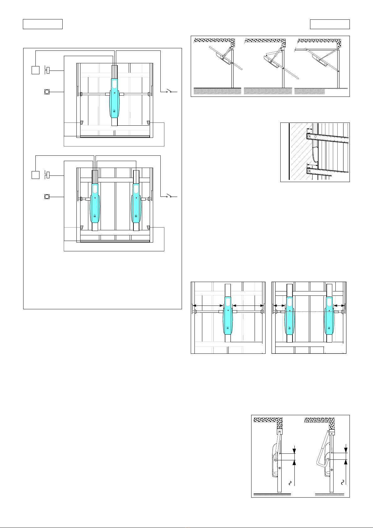
5.4.1. VERIFICA DEL SENSO DI ROTAZIONE
1) Togliere alimentazione all'impianto.
2) Portare manualmente la porta a metà apertura.
3) Bloccare l'operatore (vedi capitolo 8)
4) Ripristinare la tensione di alimentazione.
5) Inviare un impulso di apertura (OPEN) e verificare che si
comandi un'apertura della porta.
Nel caso si comandi una chiusura, è necessario invertire sulla
morsettiera della scheda le fasi del motore elettrico (cavi
marrone e nero).
Nell'applicazionecondueoperatori,aimorsetti"COM,OP,CL",
della scheda 550MP e della scheda 550 Slave, assegnare la
stessacolorazionedeicavie,dovendoinvertirelefasi,invertirle
per entrambi i motori.
5.4.2. IMPOSTAZIONE DEL TEMPO DI LAVORO
Regolare il trimmer
TR1
per ottenere un tempo di lavoro che
permetta di mantenere il motore elettrico alimentato per
qualche secondo dopo l'arrivo della porta sugli arresti
meccanici.
Questa regolazione rappresenta anche il tempo massimo per
raggiungere i finecorsa (opzionali).
5.4.3. IMPOSTAZIONE DEL TEMPO PAUSA
Selezionando la logica automatica, è possibile regolare il
tempo di pausa agendo sul trimmer
TR2
.
5.4.4 REGOLAZIONE DELLA FRIZIONE ELETTRONICA
(ANTISCHIACCIAMENTO)
L'apparecchiatura550MPèfornita diunsistemaelettronicodi
regolazione della coppia del motore che (in funzione della
regolazionestessa)limitalaspintadellaportainpresenzadiun
ostacolo.
Alla rimozione dell'ostacolo, la porta prosegue il movimento
fino al raggiungimento del fine corsa o fino al termine del
tempo di lavoro.
La regolazione si effettua agendo sul trimmer
TR3
.
Si raccomanda di tarare la frizione elettronica in conformità
alle normative vigenti.
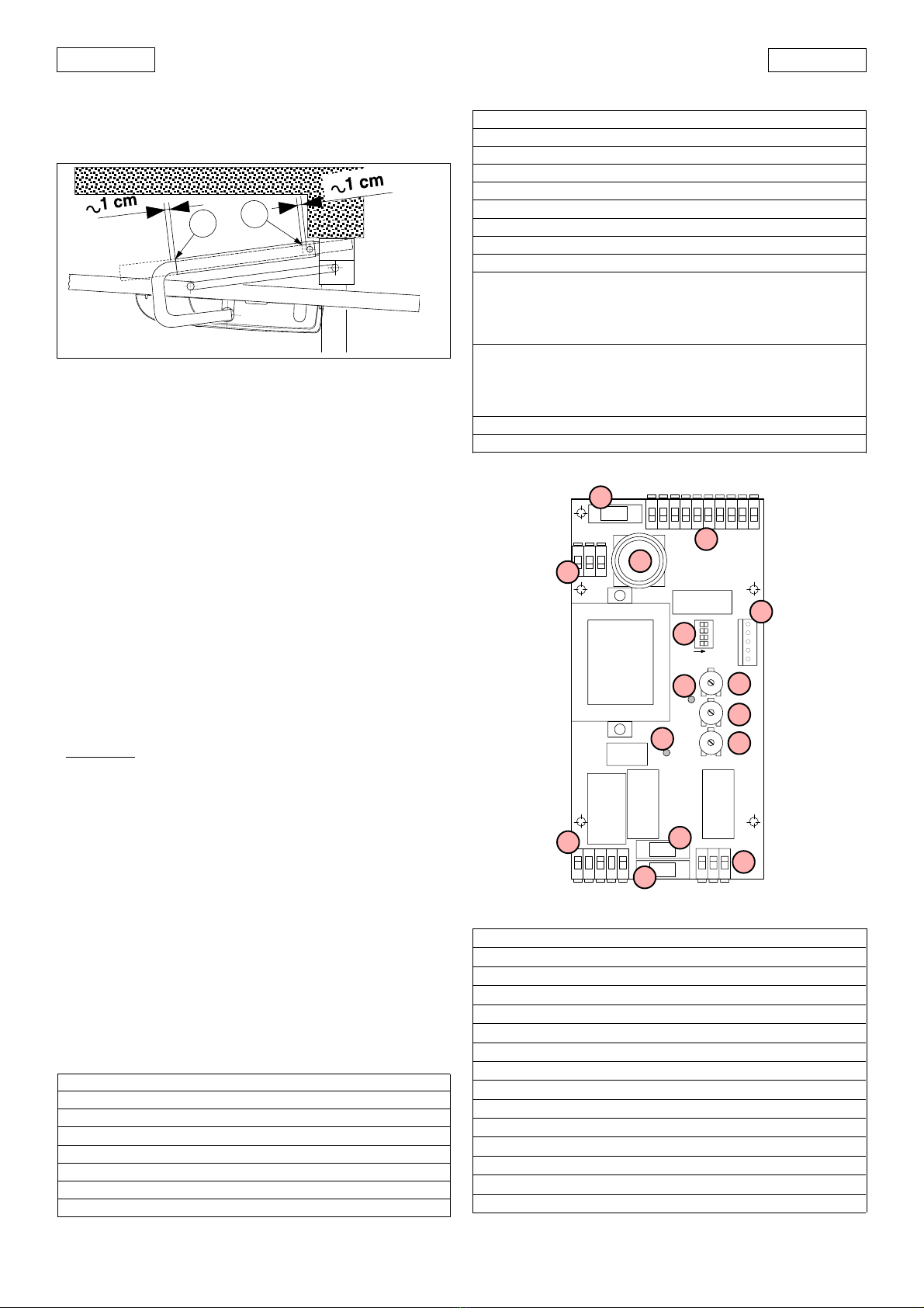
5.4.5. REGOLAZIONE DEI FINECORSA (OPZIONALI)
Aprire la porta fino al punto desiderato; regolare la camma
fino all' attivazione del micropulsante FCA (Fig. 11).
Chiudere la porta; regolare la camma fino all' attivazione del
micropulsante FCC (Fig. 11).
Serrare le viti poste sulle camme.
5.4.6. MONTAGGIO CARTER
Collegare il cavetto di OPEN al pulsante posto sul carter
dell'operatore.
Fissare il carter serrando le quattro viti laterali.
Applicare al carter a pressione, i 2 tappi di plastica nelle asole
laterali non utilizzate dall'albero dell'operatore.
Applicare al carter a pressione, il tappo di plastica nell'asola
frontale per accedere al sistema di sblocco non utilizzata.
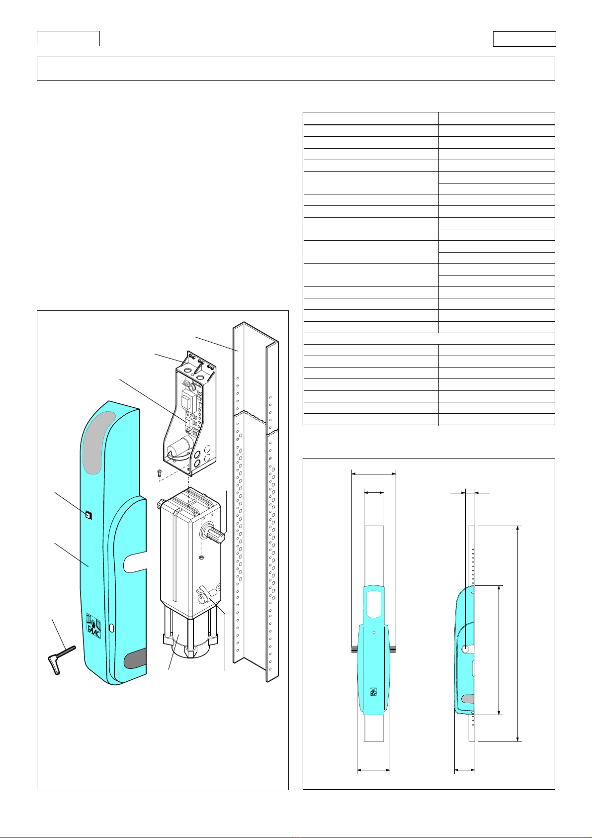
6. MONTAGGIO GRUPPO MOTORIDUTTORE
In base alle esigenze, è possibile montare il gruppo
motoriduttore in due modi:
•Con l'albero di rotazione in alto (Fig. 17)
Il supporto scheda viene fissato al motoriduttore mediante 4
viti che stringono dadi inseriti nelle apposite guide.
•Con l'albero di rotazione in basso (Fig. 18)
Il supporto scheda viene fissato alla calotta del motore
elettrico mediante 4 viti.
DS1
+
-
Fig. 16
La rotazione in senso orario dei trimmer,
incrementa le regolazioni.
La rotazione in senso antiorario dei trimmer,
diminuisce le regolazioni.

8
ITALIANO ITALIANO
Ilcarterèpredispostoperentrambeleapplicazioni(danotare
che lo sblocco viene a trovarsi in posizioni differenti); inoltre, in
corrispondenza della plafoniera trasparente, sono previste
due linguette per il serraggio del cavo di alimentazione (Fig.
19).
Nelle Figg. 17-18 è anche riportata la disposizione consigliata
di passaggio e fissaggio cavi nel supporto scheda.
LEGENDA CAVI
aa
aa
aLampeggiatore
bb
bb
bLampada cortesia esterna
cc
cc
cPulsante OPEN sul carter
dd
dd
dCollegamenti bassa tensione
ee
ee
eMotore 550 Slave
ff
ff
fAlimentazione 230V~
gg
gg
gMotore 550 I
ab c d
ef
ab c d
ef
g
Fig. 18
Fig. 19
g
Fig. 17
- Dall'esterno (Fig. 21)
1) Aprire lo sportellino di protezione ed inserire la chiave.
2)Ruotareinsensoantiorariofinoall'arrestoedestrarreilcorpo
serratura.
3) Inserire la chiave a brugola in dotazione e ruotare in senso
antiorario di circa mezzo giro fino all'arresto.
Fig. 21
SBLOCCA/UNLOCK
DEBLOQUE/ENTRIEGELT
DESBLOQUEAR
BLOCCA/LOCK
BLOQUE/VERRIEGELT
BLOQUEAR
8. RIPRISTINO DEL FUNZIONAMENTO NORMALE
Perevitarecheunimpulsoinvolontariopossaazionarelaporta
durante la manovra, prima di ribloccare l'operatore togliere
alimentazione all'impianto.
- Dall'interno (Fig. 20)
Inserire la chiave a brugola in dotazione e ruotare in senso
antiorario di circa mezzo giro fino all'arresto.
Attenzione: in base al tipo d'installazione, lo sblocco può
trovarsi sul lato destro (A) o sinistro (B).
- Dall'esterno (Fig. 21)
1) Inserire la chiave a brugola in dotazione e ruotare in senso
orario di circa mezzo giro fino all'arresto.
2) Estrarre la chiave a brugola ed inserire il corpo serratura.
3) Ruotare la chiave in senso orario fino a quando è possibile
estrarla; richiudere lo sportellino di protezione.
9 MANUTENZIONE
Effettuare almeno semestralmente le seguenti operazioni:
•Verifica della corretta regolazione di coppia del motore.
•Controllodeirullieguidediscorrimentodellaporta;eventuale
pulizia e lubrificazione.
•Controllo efficienza del sistema di sblocco.
•Controllo efficienza dei dispositivi di sicurezza.
10 RIPARAZIONI
Per eventuali riparazioni, rivolgersi ai Centri di Riparazione
autorizzati.
Fig. 20
BLOCCA/LOCK
BLOQUE/VERRIEGELT
BLOQUEAR
SBLOCCA/UNLOCK
DEBLOQUE/ENTRIEGELT
DESBLOQUEAR
SBLOCCA/UNLOCK
DEBLOQUE/ENTRIEGELT
DESBLOQUEAR
BLOCCA/LOCK
BLOQUE/VERRIEGELT
BLOQUEAR
A
B
7. FUNZIONAMENTOMANUALE
L'operatore 550 è dotato di uno sblocco d'emergenza
azionabile dall'interno; è possibile, a richiesta, applicare una
serratura sul telo che permette l'azionamento dello sblocco
dall'esterno.
Nel caso sia necessario azionare manualmente la porta a
causa di mancanza di alimentazione elettrica o disservizio
dell'automazione, è necessario agire sul dispositivo di sblocco
come segue:
- Dall'interno (Fig. 20)
Inserire la chiave a brugola in dotazione e ruotare in senso
orario di circa mezzo giro fino all'arresto.
Attenzione: in base al tipo d'installazione, lo sblocco può
trovarsi sul lato destro (A) o sinistro (B).
f

9
ITALIANO
ITALIANO
Guida per l'utente
AUTOMAZIONE 550
Leggere attentamente le istruzioni prima di utilizzare il prodotto e
conservarle per eventuali necessità future.
NORME GENERALI DI SICUREZZA
Le automazioni 550, se correttamente installate ed utilizzate,
garantiscono un elevato grado di sicurezza.
Alcune semplici norme di comportamento possono evitare inoltre
inconvenienti accidentali:
- Non sostare assolutamente sotto la porta basculante.
- Nonsostareenonpermettereabambini,personeocosedisostare
nelle vicinanze dell’automazione, specialmente durante il funzio-
namento.
- Tenere fuori dalla portata dei bambini, radiocomandi o qualsiasi
altro datore d’impulso che possa azionare la porta.
- Non permettere ai bambini di giocare con l’automazione.
- Non contrastare volontariamente il movimento della porta.
- Evitare che rami o arbusti possano interferire col movimento della
porta.
- Mantenereefficientiebenvisibiliisistemidi segnalazioneluminosa.
- Nontentaredi azionaremanualmentelaporta senondopoaverla
sbloccata.
- In caso di malfunzionamenti, sbloccare la porta per consentire
l’accesso ed attendere l’intervento tecnico di personale qualifi-
cato.
- Una volta predisposto il funzionamento manuale, prima di ripristi-
nare il funzionamento normale, togliere alimentazione elettrica
all’impianto.
- Non eseguire alcuna modifica sui componenti facenti parte il
sistema d’automazione.
- Astenersidaqualsiasi tentativodiriparazioneo d’interventodiretto
e rivolgersi solo a personale qualificato FAAC.
- Far verificare almeno semestralmente l’efficienza dell’automazio-
ne, dei dispositivi di sicurezza e del collegamento di terra da
personale qualificato.
DESCRIZIONE
L'automazione550èidealeperautomatizzareportebasculanti
a contrappesi di garages residenziali.
Ècostituitadaunoperatoreelettromeccanico,un'apparecchiatura
elettronica di comando, una lampada di cortesia e un carter di
protezione integrati in un unico monoblocco da applicare al telo
della basculante con gli opportuni accessori.
Il sistema irreversibile garantisce il blocco meccanico della porta
quando il motore non è in funzione e quindi non occorre installare
alcunaserratura;unosblocco manuale rendemanovrabilelaporta
in caso di black-out o disservizio.
La sicurezza antischiacciamento è garantita da un dispositivo
elettronico regolabile.
L'automazione 550 consente anche l'applicazione di due operatori
(550 I + 550 Slave) sulla stessa porta.
La porta normalmente si trova chiusa; quando la centralina
elettronica riceve un comando di apertura tramite il radiocomando
oqualsiasialtrodatorediimpulso,azionailmotoreelettricoottenendo
la rotazione della porta fino alla posizione di apertura che consente
l’accesso.
Seèstatoimpostatoilfunzionamentoautomatico,laportasirichiude
da sola dopo il tempo di pausa selezionato.
Seèstatoimpostatoil funzionamento semiautomatico, ènecessario
inviare un secondo impulso per ottenere la richiusura.
Un impulso di apertura dato durante la fase di apertura, provoca
sempre l’arresto del movimento.
Un impulso di apertura dato durante la fase di richiusura, provoca
l’inversione del movimento.
Un impulso di stop (se previsto) arresta sempre il movimento.
Per il dettagliato comportamento della porta nelle diverse logiche
di funzionamento, fare riferimento al Tecnico d’installazione.
Nelle automazioni possono essere presenti dispositivi di sicurezza
Fig. 2
SBLOCCA/UNLOCK
DEBLOQUE/ENTRIEGELT
DESBLOQUEAR
BLOCCA/LOCK
BLOQUE/VERRIEGELT
BLOQUEAR
RIPRISTINO DEL FUNZIONAMENTO NORMALE
Per evitare che un impulso involontario possa azionare la porta
durante la manovra, prima di ribloccare l'operatore togliere
alimentazione all'impianto.
- Dall'interno (Fig. 1)
Inserire la chiave a brugola in dotazione e ruotare in senso antiorario
di circa mezzo giro fino all'arresto.
Attenzione: in base al tipo d'installazione, lo sblocco può trovarsi sul
lato destro (A) o sinistro (B).
- Dall'esterno (Fig. 2)
1) Inserire la chiave a brugola in dotazione e ruotare in senso orario
di circa mezzo giro fino all'arresto.
2) Estrarre la chiave a brugola ed inserire il corpo serratura.
3)Ruotarelachiaveinsensoorariofinoaquandoèpossibileestrarla;
richiudere lo sportellino di protezione.
Fig. 1
BLOCCA/LOCK
BLOQUE/VERRIEGELT
BLOQUEAR
SBLOCCA/UNLOCK
DEBLOQUE/ENTRIEGELT
DESBLOQUEAR
SBLOCCA/UNLOCK
DEBLOQUE/ENTRIEGELT
DESBLOQUEAR
BLOCCA/LOCK
BLOQUE/VERRIEGELT
BLOQUEAR
A
B
(fotocellule) che impediscono la richiusura della porta quando un
ostacolo si trova nella zona da loro protetta.
Leautomazioni550 dispongono,diserie, diundispositivo disicurezza
antischiacciamento che limita la coppia trasmessa alla porta.
L’apertura manuale è possibile solo intervenendo sull’apposito
sistema di sblocco.
La segnalazione luminosa indica il movimento in atto della porta.
La luce di cortesia si attiva alla partenza del motore e permane per
un tempo di circa 90 secondi dal suo spegnimento.
FUNZIONAMENTO MANUALE
L'operatore 550 è dotato di uno sblocco d'emergenza azionabile
dall'interno; è possibile, a richiesta, applicare una serratura sul telo
che permette l'azionamento dello sblocco dall'esterno.
Nel caso sia necessario azionare manualmente la porta a causa di
mancanza di alimentazione elettrica o disservizio dell'automazione,
è necessario agire sul dispositivo di sblocco come segue:
- Dall'interno (Fig. 1)
Inserire la chiave a brugola in dotazione e ruotare in senso orario di
circa mezzo giro fino all'arresto.
Attenzione: in base al tipo d'installazione, lo sblocco può trovarsi sul
lato destro (A) o sinistro (B).
- Dall'esterno (Fig. 2)
1) Aprire lo sportellino di protezione ed inserire la chiave.
2) Ruotare in senso antiorario fino all'arresto ed estrarre il corpo
serratura.
3) Inserire la chiave a brugola in dotazione e ruotare in senso
antiorario di circa mezzo giro fino all'arresto.

9
ENGLISH
ENGLISH
1) IMPORTANT! FAAC strongly recommends to follow these instructions
carefully for the safety of persons. Improper installation or misuse of
the product will cause very serious damages to persons.
2) Read the instructions carefully before installing the product.
3) Packaging materials (plastic, polystyrene etc.) are a potential haz-
ard and must be kept out of reach of children.
4) Keep these instructions for future reference.
5) This product has been designed and manufactured only for the use
stated in this manual. Any other use not expressly set forth will affect
the reliability of the product and/or could be source of hazard.
6) FAACS.p.A. cannot beheld responsible forany damage causedby
improper use or different from the use for which the automation
system is destined to.
7) Do not use this device in areas subject to explosion: the presence of
flammable gas or fumes is a serious hazard.
8) Mechanical constructive elements must comply with UNI 8612, CEN
prEN 12604 and CEN prEN 12605 standards.
Countries outside the EC shall follow the regulations above besides
theirnationalnormativereferencesinordertooffertheutmostsafety.
9) Faac cannot be held responsible for failure to observe technical
standardsintheconstructionofgatesanddoors,orforanydeforma-
tion of the gates which may occur during use.
10) InstallationmustcomplywithUNI8612,CENprEN12453andCENprEN
12635.
The degree of safety of the automation must be C+D.
11) Beforecarryingoutanyoperations,turnoffthesystem’smainswitch.
12) An omnipower switch shall be provided for the installation with an
openingdistanceofthecontactsof 3 mm ofmore.Alternatively,use
a 6A thermomagnetic breaker with multi-pole switching.
EC MACHINE DIRECTIVE COMPLIANCE DECLARATION
(DIRECTIVE 89/392 EEC, APPENDIX II, PART B)
Manufacturer: FAAC S.p.A.
Address: Via Benini, 1 - 40069 Zola Predosa BOLOGNA - ITALY
Hereby declares that: the 550 automation system
• is intended to be incorporated into machinery, or to be assembled with other machinery to constitute
machinery in compliance with the requirements of Directive 89/392 EEC, and subsequent amendments 91/368
EEC, 93/44 EEC and 93/68 EEC;
• complies with the essential safety requirements in the following EEC Directives:
73/23 EEC and subsequent amendment 93/68 EEC.
89/336 EEC and subsequent amendments 92/31 EEC and 93/68 EEC.
and furthermore declares that unit must not be put into service until the machinery into which it is incorporated
or of which it is a component has been identified and declared to be in conformity with the provisions of
Directive 89/392 EEC and subsequent amendments enacted by the national implementing legislation.
Bologna, 1 January 1999 Managing Director
A.Bassi
13) Ensure that there is a differential switch up-line of the electrical
system, with a trip threshold of 0.03 A.
14) Check that the earthing plant is in perfect condition and connect it
to the metallic parts. Also earth the yellow/green wire of the opera-
tor.
15) The automation is fitted with an anti-crush safety system that is a
torque control device. In any case, further safety devices shall be
installed.
16) Thesafetydevices(e.g.photocells,safetyedges,etc.)protectareas
where there is a mechanical movement hazard, e.g. crushing,
entrapment and cutting.
17) Each installation must be fitted with at least one flashing light (e.g.
FAACLAMP,MINILAMP,etc.)aswellasawarningplatesuitablyfixed
to the gate, besides the safety devices as per point 16 above.
18) Faac cannot be held responsible regarding safety and correct
functioning of the automation in the event that parts other than
Faac original parts are used.
19) Use only Faac original spare parts for maintenance operations.
20) Do not carry out any modifications to automation components.
21) Theinstaller must supplyallinformation regardingmanualoperation
ofthesystemintheeventofanemergencyandprovidetheend-user
with the ”End-user Guide” attached to the product.
22) Do not allow children or adults to stand near the product during
operation.
23) Keep out of reach of children the remote radio controls and any
controldevices.Theautomationcouldbeoperatedunintentionally.
24) Theend-usermustavoidanyattempttorepairoradjusttheautoma-
tion personally. These operations must be carried out exclusively by
qualified personnel.
25) What is not explicitly stated in these instructions is not permitted.
IMPORTANT NOTICE FOR THE INSTALLER
GENERAL SAFETY REGULATIONS

10
ENGLISH ENGLISH
AUTOMATION SYSTEM 550 & 550 MP
These instructions apply to the following models:
550 I - 550 Slave
The FAAC 550 automation system is designed to operate
residential counterbalanced up-and-over garage doors.
It consists of an electromechanical operator, a control unit
with courtesy light and a protective cover integrated into a
single unit to be mounted on the garage door panel using the
relevant accessories.
The irreversible system locks the door mechanically when the
motorisnotrunning,soalockisnotrequired.Amanualrelease
device allows the door to be operated in the case of a power
failure or malfunction.
Anti-crushing safety is assured by an adjustable electronic
device.
The 550 automation system allows two operators (550 I + 550
Slave) to be installed on the same door.
The550automationsystemhasbeendesignedandconstructed
for vehicle access control. Do not use for any other purpose.
1. DESCRIPTION AND TECHNICAL SPECIFICATIONS
Fig. 1
aa
aa
aCover
bb
bb
bOPEN button
cc
cc
c550MP control unit
dd
dd
dControl unit box
ee
ee
eBack plate
ff
ff
fDrive shaft
gg
gg
gRelease device
hh
hh
hGeared motor unit
ii
ii
iRelease key
TABLE 1 550 OPERATOR TECHNICAL SPECIFICATIONS
MODEL 550
Power supply 230V~ (+6% -10%) 50Hz
Power consumption (W) 360
Max. torque (Nm) 300
Angular velocity (°/sec) 12
Duty cycle (cycles/hour) 15 (without limit switch)
25 (with limit switch)
Temperature range -20 ÷ +55°C
Geared motor weight (kg) 13
Housing protection IP 31
IP 44 (with Kit)
Max. door width (m) 3 (1 operator)
4 (2 operators)
Max. door height (m) 2.7 (1 operator)
3 (2 operators)
Max. door weight (kg/m2)10
Clutch electronic
Control unit 550MP
Geared motor dimensions LxHxD(mm)
see fig.2
Technical characteristics of electric motor
Speed (rpm) 1400
Reduction ratio 1 :700
Thermal cutout on winding 135 °C
Power (W) 350
Current draw (A) 1.5
Surge capacitor 8µF
Power supply 230V~(+ 6% -10%) 50Hz
2. DIMENSIONS
Fig. 2
175
100
160 120
50
670
1500/2000
•
values in mm
a
b
d
c
e
gh
i
f

11
ENGLISH
ENGLISH
3. ELECTRICALINSTALLATIONLAYOUT(standardsystem)
aa
aa
a550 I operator with 550MP control unit
bb
bb
b550 Slave operator
cc
cc
cFlashing light
dd
dd
dRadio receiver
ee
ee
eKeyswitch
ff
ff
fPhotocells
gg
gg
gSafety edge
ab
cd
e
f
g
f
a
cd
e
f
g
f
4. INSTALLING THE AUTOMATION SYSTEM
4.1. PRELIMINARY CHECKS
To ensure safe, proper operation of the automation system,
check the following:
• The door’s structure must be suitable for automation.
Make particularly sure that dimensions of the door meet
therequirementsgiveninthetechnicalspecificationsand
that the door is sufficiently robust.
• Check the condition of the door bearings and joints.
• Check that the door moves smoothly. If necessary clean
the tracks and lubricate them with a silicone based lubri-
cant. Do not use grease.
• Check that the door is correctly balanced.
• Removethemechanicaldoorlockssothatwhenthedoor
is closed it is locked only by the automation system.
• Check that there is an effective earth connection for the
geared motor.
The 550 automation system is designed to operate various
types of counterbalanced up-and-over garage doors. Fig. 4
shows the most common types:
asingle section outward swinging
bdouble section outward swinging
csingle section inward swinging with horizontal tracks
4.2. POSITIONING TELESCOPIC ARMS
The gap between the existing balancing arm and the frame
(distance”S1”inFig.5)mustbeat
least 15 mm to allow the straight
telescopic arms to rotate
correctly.
If not, it is possible to use curved
telescopic arms which can be
installed over the top of existing
balancing arms. Check that the
gapbetweenthedoorpaneland
the frame is at least 20 mm
(distance ”S2” in Fig. 5).
4.3. POSITIONING OPERATOR/BACK PLATE
In accordance with the measurements given in Table 1, install
either a single operator (550 I) at the centre of the door as
shown in Fig. 6 or two operators (one 550 I and one 550 Slave)
at the sides of the door as shown in Fig. 7.
Theoperator550isdesignedsothatthegearedmotorunitcan
be installed with the drive shaft at two different heights (see
section 6).
The following instructions apply to both assembly options,
although they refer specifically to installation of the operator
with the geared motor unit as it is delivered from the factory.
Fig. 3
4.4. ASSEMBLY SEQUENCE
Begininstallationwiththegaragedoorclosedandtheoperator
released (see chapter 7).
1) Determine the position of the operator shaft as follows:
• single section outward swinging garage door (Fig. 8)
When the door is closed, the axis of rotation of the drive shaft
mustbeabout10cmlowerthantheaxisofrotationofthedoor.
The telescopic arms
must be attached as
closeaspossibletothe
point where the door
arm is fixed.
10 cm
10 cm
Fig.8
==
==
Fig. 6 Fig. 7
acb
Fig. 4
S1
S2
2x0.5 4x0.5
2x0.5
3x0.5
3x0.5
2x1.5
2x1.5 +
W
5x1.5 +
W
2x1.5
3x0.5
3x0.5
2x0.5
2x0.5
4x0.5
•The cable cross-sections are expressed in mm2
Fig. 5
2x1.5 +
W

12
ENGLISH ENGLISH
• doublesectiongaragedoor
(Fig. 9)
When the door is closed, the
axis of rotation of the drive
shaft must be about 10 cm
below the axis of rotation of
the door hinge (A).
The telescopic arms must be
attachedasclose aspossible
to the point where the hinges
are fixed to the door (B).
• garage door with horizontal
guides (Fig. 10)
Theaxisofrotationofthedrive
shaft must be halfway
between the two bearings.
The telescopic arms must be
attachedascloseaspossible
to the point where the upper
and vertical guides meet.
2) Fix the back plate to the
reinforcement ribbing of the
door panel using suitable
screws for the door’s
structure.Itisadvisabletouse
nuts and bolts.
ÜPosition the back plate in such a way that the last section
without Ø 4mm holes (approximately 20 cm) is facing up-
wards.
ÜThe back plate has a series of Ø 8mm holes which, when it is
fixed, allow the operator to be installed at various heights.
Check that the fixing position of the back plate allows the
operator to be installed in accordance with the previously
determined shaft position.
Indoubleoperatorinstallations,both shaftsmustbealignedat
the same height.
10 cm
Fig. 9
AB
==
Fig. 10
3) Fix the operator to the back plate using the nuts and bolts
provided, as shown in Fig. 11.
4) Weldtheuppertelescopicarmfixingbracketsintheposition
described in the instructions for the specific type of garage
door.
In the case of curved arm installation, the brackets can be
welded directly to the existing door arms.
Fix the outer profiles of the telescopic arms to the brackets
usingthepinsand thenutsandboltsprovided, as showninFig.
11.
5) Fit the transmission shafts firmly onto the drive shaft and cut
them to size as shown in Figs. 6 and 7.
ÜIflimitswitchesareused(optional),firstfitthecamsas shown
in Fig. 11.
6)Mount the brackets on the transmission shafts and fasten
themtothedoorpanelusingscrews,takingcaretomaintain
perfect alignment.
7) Tighten the grub screws on the transmission shaft bushings.
8) Open the garage door and adjust the length of the tele-
scopic arms as follows:
• straight arms (Fig. 12)
Place the telescopic arm in position as shown in figure 12.
Cut the outer profile of the telescopic arm at point A.
Cut the inner profile at point B.
Fig. 11
AB
Fig. 12
FCC
FCA
A
B
B
B
B
C
C
D
D
E
E
F
F
G
G
H
H
I
I
L
M
ABack plate
BTelescopic arm mounting bracket
CTransmission shaft
DLimit switch cam
ETransmission shaft bracket
FSecuring grub screw
GStraight arm outer profile
HStraight arm
I Curved arm outer profile
L Curved arm
MRelease key
L

13
ENGLISH
ENGLISH
• curved arms (Fig. 13)
Place the telescopic arm in position as shown in figure 13.
Cut the outer profile of the telescopic arm at point A.
Cut the inner profile at point B.
ÜLeave a gap of about 1 cm at the ends of both profiles.
9) Fit the inner profile of the telescopic arm to the transmission
shaft and weld securely.
4.5. ADJUSTING THE COUNTERWEIGHTS
On completing mechanical installation, check whether the
door has become unbalanced by the weight of the operator
and accessories.
If necessary, change the counterweights.
For optimum balancing, the door should remain in equilibrium
in an intermediate position (45°) with the operator released.
Also check that the door opens and closes smoothly without
jerky or irregular movements.
5. START-UP
5.1. CONNECTING ELECTRONIC CARD
ÜBefore carrying out any operation on the electronic card
(connections,programming,maintenance)besuretoswitch
off the power supply.
Warning:Riskof exposuretohigh voltageswhendisconnect-
ing terminal blocks J2 or J3.
Follow points 10, 11, 12, 13 and 14 of GENERAL SAFETY
OBLIGATIONS.
AsshowninFig.3,preparetheconduitsandmaketheelectrical
connections between the 550 MP control unit and the chosen
accessories.
Always route the power cables separately from the control
and safety cables (pushbuttons, receivers, photocells, etc.).
Use separate sheaths to avoid electrical disturbance.
5.1.1. 550MP CONTROL UNIT
The550MPcontrolunitincludedinthe550Ipackageiscapable
ofcontrollingbothoperatorsinthecaseofdoubleinstallation.
Instead of a control unit, the 550 Slave has an electronic
interface card with a built-in courtesy lamp.
TABLE 2 550MP OPERATING PARAMETERS
Logic automatic/semiautomatic
Pause time adjustable by trimmer 4V50 sec.
Operating time adjustable by trimmer 4V50 sec.
Max. starting torque Yes/No
Closure stroke Yes/No
Pre-flashing 3 sec. Yes/No
Electronic clutch adjustable by trimmer 38V98%
Operating time memory Yes
TABLE 4 550MP CARD COMPONENTS
F1 Fuse F1 5x20 2A/250V (transformer secondary)
F2 Fuse F2 5x20 4A/250V (motor)
F3 Fuse F3 5x20 0.5A/250V (transformer primary)
LP1 Courtesy lamp 25W 220V E14
DL1 Mains power LED
DL2 Motor operation LED
DS1 Programming dipswitches
J1 230V~ power input terminal block
J2 Motor output terminal block
J3 Flashing light and external courtesy light output terminal block
J4 Inputs/accessories low-voltage terminal block
J5 Quick connector for decoder/RP receiver cards
TR1 Operating time adjusting trimmer
TR2 Pause adjusting trimmer
TR3 Torque adjusting trimmer (electronic clutch)
TABLE3 550MP HARDWARE CHARACTERISTICS
Power supply 230V~ (+6 -10 %) 50Hz
Max. power consumption 12VA
Max. motor load 800 W
Accessories power supply 24Vdc
Max. accessories load 500 mA
Temperature range -20°C +55°C
Safety fuses transf. primary/transf. secondary/motor
Quick connector - for decoder or RP receiver cards -
Terminal blocks pull-out
Open
Terminal block inputs Stop
Closure safeties
Limit switches
flashing light
Terminal block outputs motor
230V~ external courtesy light
24Vdc accessories power supply
Courtesy timing 90 sec.
Max. external courtesy lamp load 100W
5.1.2. 550MP CARD LAYOUT
AB
Fig. 13
ON
+
+
+
-
-
-
1432
550MP
F1
J4
LP1
J3
J5
DS1
DL1 TR1
TR2
TR3
J1
J2
F3
F2
DL2
Fig. 14

14
ENGLISH ENGLISH
5.1.3. ELECTRICAL CONNECTIONS
ON
+
+
+
-
-
-
1432
132 456
789
10 11 12 13 14 15 16 17 18 19
J4
J3
J1 J2
GROUND
N
F
COM
OP
CL
COM
FLASH
EXT.LAMP
FCC
FCA
FSW
STOP
OPEN
M
230V~
C
8µF
5
4
3
2
1
1
2
(+6% -10%)
550 SLAVE
550 MP
M
C
8µF
50Hz
COM
OP
CL
456
FAACLAMP
MINILAMP
230V~
max 25W
230V~
max 25W
J5
TR1
TR2
TR3
DS1
DL1
DL2
GROUND
Fig. 15
5.2. DESCRIPTION
5.2.1. TERMINAL BLOCK J1 (high voltage)
Terminalblockfor230V~50Hzpowersupply(F=PhaseN=Neutral).
Connect the electrical system earth and the operator earth
cable to the ”Ground” terminal.
5.2.2. TERMINAL BLOCK J2 (high voltage)
230V~ terminal block for connecting the electric motor.
BLACK CABLE AND BROWN CABLE = electric motor phases (OP/CL)
BLUE CABLE = electric motor common (COM)
The surge capacitor must be connected in parallel with the
phases.
5.2.3. TERMINAL BLOCK J3 (high voltage)
230V~ terminal block for connecting:
• Flashing light (FLASH) max. 60W.
• Courtesy light of 550 Slave (EXT LAMP) or alternatively an
external courtesy light max. 100W.
5.2.4. TERMINAL BLOCK J4 (low voltage)
FCC= Closure limit switch contact (N.C.)
Theclosurelimitswitch(optional)consistsofamicroswitch
which is activated by the cam when the door reaches
theclosedpositionandstopsmovementafter2seconds.
FCA= Opening limit switch contact (N.C.)
The opening limit switch (optional) consists of a
microswitch which is activated by the cam when the
door reaches the open position and stops movement
immediately.
Ü
Iflimitswitchdevicesarenotused,jumperFCCand FCA with
the common inputs.
= Common inputs/Accessories power supply negative
= Accessories power supply positive 24Vdc (+)
The max. accessories load is 500mA.
To calculate absorption values, refer to the instructions
for the individual accessories.
FSW= Closing safeties contact (N.C.)
The term ”safeties” refers to any device (photocells,
safety edges, etc.) with an N.C. contact that reverses
the closing movement of the door when it detects an
obstacle within the area it protects.
These devices have no effect during opening.
If the safeties are engaged when the door is closed,
stopped or open, they prevent it from moving.
To install a number of safety devices, connect the N.C.
contacts in series.
Ü
If safety devices are not connected, jumper FSW with the
common inputs.
STOP= STOP command (N.C.)
Anydevice(e.g.button)whichstopsthedoormovement
by opening a contact.
To install a number of stop devices, connect the N.C.
contacts in series.
Ü
If Stop devices are not connected, jumper the STOP and
common inputs.
OPEN=OPEN command (N.O.)
Any device (button, detector, etc.) which activates
door opening (or closing) by closing a contact.
To install a number of Open devices, connect the N.O.
contacts in parallel.
5.2.5. CONNECTOR J5 (low voltage)
ConnectorJ5isusedforquickconnectionofMINIDEC,DECODER
and RP RECEIVER cards.
Fittheaccessoriescardssothattheircomponentsidefacesthe
inside of the 550MP card.
Disconnect power before engaging or removing.

15
ENGLISH
ENGLISH
5.3. PROGRAMMING
Toprogramoperationoftheautomation,setthedipswitchesas
shown in the following diagram.
ÜDisconnect the power supply momentarily from the card
after every programming operation.
SW1 - Max. starting torque
Themaximumstartingtorqueallowstheelectronicclutchsetting
(Trimmer TR3) to be disabled in the initial movement phase.
SW2 - Operating logic
Theoperationoftheautomationinthevarious logicsisshownin
Tables 5-6.
SW3 - Closure stroke
The closure stroke is enabled only if the limit switches are used.
It delays cut-out of the motor by 4 seconds after activation of
the closing limit switch.
SW4 - Pre-flashing
Itispossibletoselect 3 sec. pre-flashingoftheflashinglightprior
toeverymovement.Thiswarnsanyoneinthevicinityofthedoor
that it is about to move.
Logic SW2
Automatic ON
Semiautomatic OFF
Max. starting
torque SW1
Yes ON
No OFF
Closure stroke SW3
Yes ON
No OFF
Pre-flashing SW4
Yes ON
No OFF
1234
ON
OFF
TABLE 6 SEMIAUTOMATIC LOGIC
SAFETIES
no effect
(preventsopening)
prevents closure
reverses movement
no effect
no effect
(prevents op/cl)
DOOR STATUS
CLOSED
OPEN
CLOSING
OPENING
STOPPED
OPEN
opens (1)
closes (1)
reverses movement
stops
closes/opens (1)(2)
STOP
no effect
no effect
stops
stops
no effect
PULSES
PULSES
SAFETIES
no effect
(preventsopening)
freezes pause until
disengagement
reverses movement
no effect
no effect
(prevents op/cl)
STOP
nbo effect
stops counting of pause
time
stops
stops
no effect
DOOR STATUS
CLOSED
OPEN ON PAUSE
CLOSING
OPENING
STOPPED
OPEN
opens the door and recloses
after pause time (1)
closes (1)
reverses movement
stops
closes/opens (1)(2)
TABLE 5 AUTOMATIC LOGIC
(1) with pre-flashing selected, the movement begins after 3 sec.
(2) giving an OPEN signal with the door stopped starts the opposite movement to the
previous one.
5.4. TESTING THE AUTOMATION SYSTEM
Notes on operation:
•The 550MP card performs an electronic check (for which the
motormustbeconnected)priortoeverystart-up.Ifanyattempt
is made to operate the card without the motor load or with an
insufficientload,voltageisnotsuppliedtothemotoroutputand
LED DL2 flashes to signal the fault.
•There must be a delay of at least 1.5 seconds between one
OPEN signal and the next.
•Thecourtesylightcomesonwhenthemotorstartsandstayson
for about 90 seconds after the end of the movement.
5.4.1. CHECKING DIRECTION OF ROTATION
1) Turn off the power supply to the system.
2) Move the door manually to its half open position.
3) Lock the operator (see chapter 8)
4) Turn the power supply back on.
5) Send an open signal (OPEN) and check that this causes the
door to open.
If the door closes, invert the electric motor phase wires on the
card terminal block (brown and black wires).
In the double operator installation, connect the same colour
wires to the COM, OP and CL terminals on the 550MP card and
the550Slavecard.Ifyouhavetoinvertthewires,invertthemon
both motors.
5.4.2. SETTING THE OPERATING TIME
Set trimmer
TR1
to obtain an operating time such that the
electric motor remains powered up for a few seconds after the
door has reached the mechanical stops.
This setting also represents the maximum time for reaching the
limit switches (optional).
5.4.3. SETTING PAUSE TIME
By selecting automatic logic it is possible to set the pause time
by means of the trimmer
TR2
.
5.4.4 SETTINGELECTRONICCLUTCH(ANTI-CRUSHINGSAFETY
SYSTEM)
The550MPcontrolunitisequippedwithanelectronicsystemfor
regulating the motor torque which limits the thrust of the door
when obstructed by an obstacle (depending on the setting).
Whentheobstacleisremoved,thedoorcontinuesitsmovement
until it reaches the limit switch or until the end of the operating
time.
The setting is made by means of trimmer
TR3
.
Makesurethattheelectronicclutchiscalibratedinaccordance
with current applicable legislation.
5.4.5. ADJUSTMENT OF LIMIT SWITCHES (OPTIONAL)
Open the door as far as required, then turn the cam until it just
trips microswitch FCA (Fig.11).
Close the door, then turn the cam until it just trips microswitch
FCC (Fig.11).
Tighten the screws on the cams.
5.4.6. MOUNTING COVER
Connect the OPEN cable to the button on the operator cover.
Fasten the cover in place by tightening the four screws at the
sides.
Pushthe2plasticcaps ontothesideslotsonthe cover notused
by the operator shaft.
Push the plastic cap onto the unused front slot on the cover for
gaining access to the release system.
6. MOUNTING GEARED MOTOR UNIT
Depending on requirements, the geared motor unit can be
mounted in two different ways:
•With the drive shaft at the top (Fig. 17)
The card support is fixed to the geared motor by means of 4
bolts which engage with nuts inserted in the guides.
•With the drive shaft at the bottom (Fig. 18)
The card support is fixed to the electric motor cap by means
of 4 screws.
DS1
+
-
Fig. 16
Turningthetrimmerclockwiseincreasestheset
values.
Turning the trimmer anticlockwise reduces the
set values.

16
ENGLISH ENGLISH
Thecoverisdesignedforbothapplications(notethatinthetwo
cases the release device is located in different positions). There
are also two tabs for fixing the power cable to the clear light
fixture (Fig. 19).
Figs.17-18 also show the recommended layout for routing and
fixing the cables in the card support.
KEY TO CABLES
aa
aa
aFlashing light
bb
bb
bExternal courtesy light
cc
cc
cOPEN button on cover
dd
dd
dLow-voltage connections
ee
ee
e550 Slave motor
ff
ff
f230V~ power supply
gg
gg
g550 I motor
ab c d
ef
ab c d
ef
g
Fig. 18
Fig. 19
g
Fig. 17
- From outside (Fig.21)
1) Open the safety door and insert the wrench.
2)Turnanticlockwiseasfaraspossibleandremovethelockunit.
3)Insertthehexwrenchprovidedand turnanticlockwiseabout
half a turn until the stop is reached.
Fig.21
SBLOCCA/UNLOCK
DEBLOQUE/ENTRIEGELT
DESBLOQUEAR
BLOCCA/LOCK
BLOQUE/VERRIEGELT
BLOQUEAR
8. RETURNING TO NORMAL OPERATION
To prevent an accidental movement from activating the door
during the operation, disconnect the power supply from the
system before locking the operator again.
- From inside (Fig.20)
Insert the hex wrench provided and turn anticlockwise about
half a turn until the stop is reached.
Note:depending on the type of installation, the release device
may be on the right (A) or the left (B).
- From outside (Fig.21)
1)Insertthehexwrenchprovidedandturnclockwiseabouthalf
a turn until the stop is reached.
2) Remove the hex wrench and insert the lock unit.
3) Turn the wrench clockwise so that it can be removed; close
the safety door again.
9 MAINTENANCE
Carry out the following operations at least every six months:
•Check that the motor torque is set correctly.
•Check the door’s rollers and sliding guides; clean and
lubricate if necessary.
• Check the efficiency of the release system.
•Check the efficiency of the safety devices.
10 REPAIRS
For repairs contact authorised FAAC Service Centres.
Fig. 20
BLOCCA/LOCK
BLOQUE/VERRIEGELT
BLOQUEAR
SBLOCCA/UNLOCK
DEBLOQUE/ENTRIEGELT
DESBLOQUEAR
SBLOCCA/UNLOCK
DEBLOQUE/ENTRIEGELT
DESBLOQUEAR
BLOCCA/LOCK
BLOQUE/VERRIEGELT
BLOQUEAR
A
B
7. MANUALOPERATION
The operator 550 is equipped with an emergency release
device that can be operated from inside the garage. On
request,alock canbefittedto thedoorpanel whichallowsthe
release device to be operated also from outside the garage.
If the door has to be operated manually due to a power failure
oramalfunctionoftheautomationsystem,operatetherelease
device as follows:
- From inside (Fig. 20)
Insertthehex wrenchprovidedandturn clockwiseabouthalfa
turn until the stop is reached.
Warning:depending on the type of installation, the release
device may be on the right (A) or left (B).
f

17
ENGLISH
ENGLISH
User’s guide
550 AUTOMATION SYSTEM
Read the instructions carefully before using the product and
keep for future reference.
GENERAL SAFETY RULES
If correctly installed and operated, the 550 automation systems
ensure a high level of safety.
However, some simple rules should be followed to avoid
accidents:
- Do not stand underneath the garage door.
- Do not stand in the vicinity of the automation or allow anyone
else, especially children, to do so and do not place objects in
the vicinity of the automation. This is particularly important
during operation.
- Keep remote controls and other control devices out of the
reach of children to prevent them from accidentally operating
the door.
- Do not allow children to play with the automation.
- Do not deliberately obstruct the movement of the door.
- Make sure that branches or bushes do not interfere with the
movement of the door.
- Keeptheluminoussignallingsystemsefficientandclearlyvisible.
- Do not attempt to operate the door manually without first
releasing it.
- In the event of a malfunction, release the gate to allow access
and call a qualified technician for service.
- Aftersettingmanualoperation,disconnecttheelectricitysupply
from the system before returning to normal operation.
- Do not make any modifications to components belonging to
the automation system.
- Do not attempt to perform any repair work or tamper with the
automation. Call FAAC qualified personnel for repairs.
- At least once every six months have the automation, the safety
devices and the earth connection checked by a qualified
technician.
DESCRIPTION
The 550 automation system is ideal for operating residential
counterweighted up-and-over garage doors.
It consists of an electromechanical operator, a control unit with
courtesylightandaprotectivecoverintegratedintoasingleunit
to be mounted on the garage door panel using the relevant
accessories.
The irreversible system locks the door mechanically when the
motor is not running, so a lock is not required. A manual release
device allows the door to be operated in the event of a power
failure or malfunction.
Anti-crushingsafetyisassuredbyanadjustableelectronicdevice.
The 550 automation system allows two operators (550 I + 550
Slave) to be installed on the same door.
The door is normally closed. When the control unit receives an
opening signal via the radio control or another control device, it
activates the electric motor which rotates the door to the open
position to allow access.
If automatic operation has been set, the door closes again after
the selected pause time.
If semiautomatic operation has been set, a second signal must
be given to close the door again.
Giving an opening signal while the door is opening always
causes the door to stop moving.
Giving an opening signal while the door is closing causes the
door to reverse its direction of movement.
A stop signal (if available) always stops the door.
Ask the installation engineer if you need further information on
operation of the door in the various operating logics.
The automation systems may include safety devices (photocells)
which prevent the door from closing when an obstacle lies within
the area they are protecting.
Fig. 2
SBLOCCA/UNLOCK
DEBLOQUE/ENTRIEGELT
DESBLOQUEAR
BLOCCA/LOCK
BLOQUE/VERRIEGELT
BLOQUEAR
RETURNING TO NORMAL OPERATION
To prevent an accidental movement from activating the door
during this operation, disconnect the power supply from the
system before locking the operator again.
- From inside (Fig. 1)
Insertthehex wrenchprovidedand turnanticlockwiseabout half
a turn until the stop is reached.
Note: depending on the type of installation, the release device
may be on the right (A) or the left (B).
- From outside (Fig. 2)
1) Insert the hex wrench provided and turn clockwise about half
a turn until the stop is reached.
2) Remove the hex wrench and insert the lock unit.
3)Turnthe wrenchclockwisesothat itcanbe removed;closethe
safety door again.
Fig. 1
BLOCCA/LOCK
BLOQUE/VERRIEGELT
BLOQUEAR
SBLOCCA/UNLOCK
DEBLOQUE/ENTRIEGELT
DESBLOQUEAR
SBLOCCA/UNLOCK
DEBLOQUE/ENTRIEGELT
DESBLOQUEAR
BLOCCA/LOCK
BLOQUE/VERRIEGELT
BLOQUEAR
A
B
The 550 automation systems are provided as standard with an
anti-crushing safety device which limits the torque transmitted to
the door.
The door can be opened manually by using the release system.
The light flashes to indicate that the gate is moving.
The courtesy light comes on when the motor starts and remains
on for about 90 seconds after it has stopped.
MANUAL OPERATION
The 550 operator is equipped with an emergency release device
that can be operated from inside the garage. On request, a lock
can be fitted to the door panel to allow the release device to be
operated from outside.
Ifthedoor hastobeoperatedmanuallyduetoanelectricpower
failure or malfunction of the automation, use the release device
as follows:
- From inside (Fig. 1)
Insert the hex wrench provided and turn it about half a turn
clockwise until it stops.
Note: depending on the type of installation, the release device
may be on the right (A) or left (B).
- From outside (Fig. 2)
1) Open the safety door and insert the wrench.
2) Turn anticlockwise as far as possible and remove the lock unit.
3) Insert the hex wrench provided and turn anticlockwise about
half a turn until the stop is reached.
Other manuals for 550
6
This manual suits for next models
1
Table of contents
Languages:
Other FAAC Garage Door Opener manuals

FAAC
FAAC DOMOGLIDE-B7 User manual

FAAC
FAAC R180 User manual

FAAC
FAAC Estate Swing E-SC 1102 Series User manual

FAAC
FAAC D1000 User manual

FAAC
FAAC S2500I CERNIERA User manual

FAAC
FAAC D064 User manual

FAAC
FAAC S800 CBAC KIT-100 User manual

FAAC
FAAC 739 240V User manual

FAAC
FAAC 565 User manual

FAAC
FAAC 391 User manual
Popular Garage Door Opener manuals by other brands

Grifco
Grifco eDrive 2.0 M123ED2 installation manual

Chamberlain
Chamberlain LiftMaster Professional VSL595 Programming instructions

Lynx
Lynx Napoleon Lynx LDT owner's manual

BFT
BFT EOS 120 VENERE D Installation and user manual

Chamberlain
Chamberlain 8355W manual

Craftsman
Craftsman 57993 installation guide