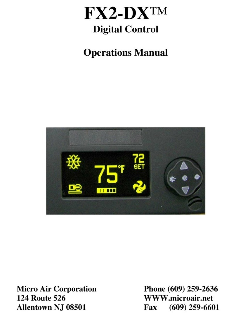
Micro Air Corporation FX-1 User manual


CONTENTS
FX-1 Operations Manual
MicroAir Corporation
124 Route 526
Allentown, NJ 08501
INTRODUCTION ......................................................................................................................................... 1
BASIC OPERATION.................................................................................................................................... 2
SYSTEM OVERVIEW .................................................................................................................................. 3
OPERATOR CONTROLS AND DISPLAY PANEL ........................................................................................ 4 & 5
DUAL BUTTON FUNCTIONS........................................................................................................................ 5
MODES OF OPERATION ...................................................................................................................... 6 & 7
AWAY-MODE .......................................................................................................................................... 6
FAN MODES ............................................................................................................................................ 7
ENTERING THE PROGRAM MODE................................................................................................................ 8
DEFAULT PROGRAM TABLE ....................................................................................................................... 9
PROGRAMMING ...................................................................................................................................... 10
PROGRAMMING .................................................................................................................... 9 THROUGH 12
RESET MEMORIZED DEFAULTS ................................................................................................................ 12
MEMORIZE NEW PROGRAM DEFAULTS ..................................................................................................... 12
AMBIENT AIR TO WATER TEMPERATURE DIFFERENTIAL CHART ................................................................. 13
SPECIFICATIONS ..................................................................................................................................... 14
WIRING DIAGRAM .................................................................................................................................. 15
INSTALLATION OVERVIEW ....................................................................................................................... 16
NOTES: All items labeled COMP should be considered Electric Heater applications.
When the Alternate Air Sensor is required the Outside Air Sensor is not available.
Copyright © 1997 Micro Air Corporation, All Rights Reserved
Nopartofthispublicationmaybereproduced,translated,storedinaretrievalsystem,ortransmittedonanyform
orbymeanselectronic,mechanical,photocopying,recordingorotherwisewithoutpriorwrittenconsentbyMicro
Air Corporation.
Every precaution has been taken in the preparation of this manual to insure its accuracy. However, Micro Air
Corporation assumes no responsibility for errors and omissions. Neither is any liability assumed for damages
resulting from the use of this product and information contained herein.

FX-1Air Handler Control Operations Manual
Page 1Revision: 04 04/09/09
INTRODUCTION
The FX-1 Air Handler Control is designed for use with Marine Chilled Water Air Conditioning
Systems. FX-1 Air Handler Control has a universal power supply that operates on 115, 230, 50
or 60 Hz AC power. FX-1 Air Handler Control includes the following standard and optional
features:
Standard Features
User friendly 4 button display panel requires no manual
for basic operation.
Five volt logic and micro controller located in the display.
3-digit 7-segment display indicates ° F or ° C.
Room temperature sensor integral in the display panel.
Automatic fan speed reduction as set point is approached.
Six [6] programmable manual fan speeds.
19 programmable parameters for custom installations.
Water In Sensor allowing individual cabin heating.
Away Mode for controlling relative humidity.
Universal AC power supply.
Nonvolatile memory retains settings without batteries.
Programmable display brightness control for night use.
Optional Features
The following optional items can be added by plugging the device into the appropriate jack and
making the necessary programming changes.
Outside air temperature sensor
Alternate air temperature sensor
Custom paintable display panels
Electric Heat Chill Chaser Option
This manual is intended to provide information necessary to insure proper installation and
operation of the FX-1 Air Handler Control. Poor installation and MISUNDERSTOOD operating
parameters will result in unsatisfactory performance and premature failure of the FX-1 Air Handler
Control.
Read This Manual Completely Before Proceeding !
If you require assistance prior to or during the installation of the FX-1 Air Handler Control call
Micro Air at 609-259-2636 or Fax your questions to Micro Air at 609-259-6601.
The FX-1 Air Handler Control is covered under existing Micro Air Corp. Warranty Policy.
Incorrectinstallation,neglectandsystemabuse arenotcovered under MicroAir's warrantypolicy.

FX-1Air Handler Control Operations Manual
Page 2Revision: 04 04/09/09
BASIC OPERATION
POWERBUTTON Press the power button once to toggle the unit to the on mode. Press the power
button again to toggle the unit to the off mode.
UP BUTTON Momentarily press and the
set point will appear in the temperature
display. The set point increases one degree
each time the up button is pressed and
released.
DOWNBUTTON Momentarilypressand
release to display the set point. The set
pointisdecreased onedegree eachtime the
down button is pressed and released.
SELECT BUTTON The select button is
used to select one of 4 Operating Modes.
Press and release to advance to the next
mode. Continue to press and release until
the desired Operating Mode is reached.
ThemodeselectedisindicatedbytheMode
LED.
THREE DIGIT DISPLAY The inside
[supply]temperature isdisplayedwheneverthecontrol isturned on.The displayprovides areadout
of the inside air temperature.
HEAT MODE LED The heat mode LED is lit when Heating is selected.
COOL MODE LED The cool mode LED is lit when the Cooling is selected.
AUTO LED The auto LED is lit when the Automatic Heating or Cooling Mode is selected. The
control will automatically switch to heating or cooling when this mode is selected.
AWAY MODE LED The away LED is lit when the Away Mode [ Rh Control ] is selected.
AUTO FAN SPEEDS The fan speeds are automatically reduced as the set point is approached.
FAN SPEED BAR GRAPH There are six [6] individual fan speed LED's. Each LED represents
one[1]fanspeed.Lowfan[1]isindicatedbyilluminatingthe firstLED.High fanspeedis indicated
by illuminating all six [6] LED's.
MANUAL FAN SPEEDS Manual fan speed settings are available via system programming. See
the first programming item on page 10.
OPERATING LED The system operating status [ water valve open or closed ] is indicated by the
operating LED.

FX-1Air Handler Control Operations Manual
Page 3Revision: 04 04/09/09
OVERVIEW
FX-1 Air Handler Control is a user friendly, easy to operate, programmable temperature control.
Press the ON/OFF button once to engage the system. The display indicates room temperature when
the system is on and the display is blank when the system is off.
Press and release the Select Button until the desired Mode LED is illuminated.
Set the room temperature by pressing the up or down button. The set point can be viewed by
momentarily pressing and releasing the up or down button.
Fan speed operation is automatic. The fan speed decreases as room temperature is approached. The
fan will operate at low speed when set point is satisfied. Manual fan speeds can be selected by
entering the program mode and selecting the desired fan speed. The fan will operate at the speed
selected and will not change speeds with room temperature. See page 10 of this manual for
programming instructions.
The fan can be programmed to cycle on and off with the Heating and Cooling demand. Normally
the automatic fan speed operation is reversed in the heating mode, however, the fan speeds can be
programmed to operate the same as in the cooling mode.
NORMAL HEATING OR COOLING CYCLE
When heating or cooling is called for the water valve switches to the appropriate mode. Four [4]
seconds later the automatic fan control adjusts the fan to the proper speed. When the demand is
satisfied,thewatervalvecyclesoffandthefanreturnstolow speed.Ifcooling isrequired,the water
valve will not open unless adequate cooling water is available. The fan will remain in low speed
until adequate cooling water is available. If heating is required the valve will not open unless
adequate heating water is available. The fan remains in low speed until adequate heating water is
available. The water temperature can be viewed by simultaneously pressing the Up and Down
Buttons while in the On Mode. Heat will be supplied when no heating water is available if the
Optional Electric Heater [Chill Chaser] has been installed.
While in a Heating or Cooling Mode the controller will maintain a two degrees Fahrenheit (2 °F)
temperaturevariation.Afourdegreeswingisrequiredtocausetheunittoshifttotheoppositemode.
Once in a new mode, Heating or Cooling, FX-1 Air Handler Control will maintain a two degree
differential. AWAY-MODE
Whilein theonmode,pressthe SelectButtonuntil theAwayModeLEDis lit.Everyfour (4)hours,
the fan is started and air circulated for thirty (30) minutes. During this time the air temperature is
sampled and entered into memory. The cooling cycle is started and continues until the temperature
is lowered 2 ° F. The system is allowed a maximum of one hour running time to reach the desired
temperature. Four (4) hours after the temperature is satisfied or the Cooling Mode times out, the
cycle is repeated. During the humidity cycle the Operating LED is lit while the system is Cooling.
MEMORY
Memory: FX-1 Air Handler Control has nonvolatile memory which requires no batteries or any
formofbackuppower.Whenpowerislost theoperatingparameters areretainedindefinitely. When
power is restored, the control resumes operating as last programmed. All operating and program-
ming parameters are entered into nonvolatile memory instantly and are retained indefinitely.

FX-1Air Handler Control Operations Manual
Page 4Revision: 04 04/09/09
OPERATOR CONTROLS AND DISPLAY PANEL
Refer to figure 1 for the buttons locations and display functions listed on the following pages.
1.POWERBUTTON The power button is used to toggle between the onand offmodes. Press the
power button once to toggle the unit to the on mode. Press the power button again to toggle to the
off mode.
2.DOWNBUTTON Momentarilypressandreleasethedownbuttontodisplaythesetpoint.Press
and release the down button to decrease the set point. The set point is decreased one degree each
time the down button is pressed and released. The lowest set point allowed is 55 ° Fahrenheit. The
down button is used in conjunction with the up button to display Water In temperature when the
control is on. The down button is also used to reduce program values in the program mode.
3. UP BUTTON Momentarily press the up button and the set point will appear in the temperature
display. Press and release the up button to increase the set point one degree. The set point is
increased by one degree each time the up button is pressed and released. The highest set point
allowed is 85 ° F. The up button is used with the down button to display the Water In temperature
when the control is on. The up button is also used to increase program values in the program mode.
4. SELECT BUTTON The select button is used to select one of the four operating modes. Press
and release the select button and the FX-1 Air Handler Control will advance to the next mode.
Continue to press and release the select button until the desired operating mode is reached. The
mode selected is indicated by the Mode LED, i.e., Cool, Heat, Automatic or Away Mode.

FX-1Air Handler Control Operations Manual
Page 5Revision: 04 04/09/09
OPERATOR CONTROLS AND DISPLAY PANEL
5. COOL MODE LED The cool mode LED will be lit when the Cooling Mode has been selected.
HEAT MODE LED The heat mode LED will be lit when the Heat Mode
has been selected. The heat mode LED is also lit when the optional electric
heat is installed and the heat mode is selected. Electric heater status, on or
off, is indicated by the Operating LED.
6.AwayModeLED TheAwayModeLEDwillbelitwhentheAwayMode
has been selected. This mode is used to control moisture during periods
when the vessel is unoccupied.
7. READY LED The Ready LED is on whenever AC ready is supplied to
thecontrol.The ready LEDremains on whenthecontrol is inthe on andoff
modes.
8. THREE DIGIT SEVEN SEGMENT DISPLAY The inside air temperature is displayed in the
window whenever the control is turned on. The three digit 7 segment display provides a readout of
the inside air temperature which is located in the face plate. An optional alternate air sensor is
available for installations that cannot use the face plate sensor.
The display also indicates program information, fault codes and outside air temperature when the
optional outside air sensor is installed.
The display will momentarily indicate the set point when either the up or down button is pressed
and released.
When the control resumes operation after a power interruption all the display LEDs will turn on for
one second. This is a normal operating condition and is referred to as "Power On Reset".
9. FAN SPEED BAR GRAPH There are six [6] individual fan speed LED's in the Fan Speed Bar
Graph. Each LED represents one [1] fan speed. Low fan speed [1] is indicated by illuminating the
firstLED.Highfanspeedisindicatedbyilluminatingallsix[6]LED's.Anyofthesix[6]fanspeeds
available are displayed by illuminating the appropriate LED's.
10. OPERATING STATUS LED The Operating LED is on when the water valve is on and off
when the water valve is off. The Operating LED also indicates when the optional electric heater is
turned on.
DUAL BUTTON FUNCTIONS
Up & Down Buttons… Simultaneously Press the Up and Down buttons, while in the Off Mode, to
viewtheoutsideairtemperature,providingtheOPTIONAL OUTSIDE AIR TEMPERATURE SENSOR hasbeen
installed. Parameter P-12 has to be programmed On.
Simultaneously Press the UP & Down Buttons while in the program mode to set new custom
programming defaults.

FX-1Air Handler Control Operations Manual
Page 6Revision: 04 04/09/09
MODES OF OPERATION
Off Mode
When the FX-1 Air Handler Control is in the off mode, all control outputs are turned off.
Programparametersandusersettingsaresavedinnonvolatilememory.Theprogrammodecanonly
be accessed from the off mode. The Ready LED remains lit in the off mode.
On Mode
When the control is in the on mode, power will be supplied to the appropriate control outputs and
the display will indicate the current state of operation. The operating and program parameters
resume based on those stored the last time the unit was operating.
Cool Only Mode
When Cool LED is on, only the cooling systems are selected and operated as required. When the
temperature drops below the set point, the system will not automatically switch to the heating
mode. Cooling only is available for customers that do not want automatic cooling and heating
operation.
Heating Mode Only
When the Heat LED is on, only the heating systems are selected and operated as required. Should
the temperature rise above the set point, the system will not automatically switch to the cooling
mode. Heating only is supplied for customers that require the system to not automatically switch
from the heating to the cooling mode.
Automatic Mode
WhentheAutomaticLEDis on,bothheating andcoolingare suppliedasrequired.
The heat and cool LEDs will be lit according to the mode required. When the
systemrequires thewatervalve tobe turnedon forheating orcoolingtheOperating
LED will turn on when the valve is on and will turn off when the valve is off.
Temperature in a given mode will be maintained at two degrees Fahrenheit ( 2 ° F
), however, a four degree difference is required to allow the control to change
modes. Once in a new mode, the temperature will remain within two degrees
Fahrenheit ( 2 ° F ) of the set point.
Away Mode
While in the on mode, press the Select Button until the Away Mode LED is illuminated. The first
humidity cycle will start in one minute. Every four (4) hours, the fan is started and air circulated
for thirty (30) minutes. During this time the air temperature is sampled and entered into memory.
The cooling cycle is started and continues until the temperature is lowered 2 ° F. The system is
allowed a maximum of one hour running time to reach the desired temperature. Four (4) hours after
thetemperatureis satisfiedorthe one hourtimer runs outthe cycle isrepeated. During thehumidity
cycle the Operating LED is lit while the water valve is turned on and the system is cooling.

FX-1Air Handler Control Operations Manual
Page 7Revision: 04 04/09/09
FAN MODE
Automatic Fan Mode
FX-1 Air Handler Control has six automatic fan speeds available.
Speed six is high, three is medium and one is low or the slowest speed.
Automaticfan modeallowstheFX-1Air HandlerControl todetermine
the required fan speed based on room temperature. The closer the
room temperature is to the set point, the slower the fan will run. This
permits a balance between the most efficient temperature control and
slower, quieter fan speeds. Automatic fan operation is the factory
default, however, manual fan speed control is available.
Manual Fan Mode
Program parameter one [1] is used to select one of the six (6) manual
fan speeds available. Six (6) is the fastest and one (1) represents the
slowest fan speed. Manual fan mode allows the user to select and
maintain the desired fan speed manually. When a manual fan speed has
been selected, the fan speed bar graph will indicate the speed selected
by the number of LED's lit. Select speed 3, for example, and the first
3 LEDs in the fan bar graph will turn on. Manual Fan Mode is
sometimes preferred when room temperature is constantly changing
due to varying heat loads.
PROGRAM MODE
Program Mode Overview
The program mode is used to adjust the systems operating
parameters to suit the particular needs of individual users.
The program mode is also used to tailor the air-condition-
ing system for the most efficient operation within an
installation. Installation variables such as, ducting, sensor
location and system layout effect the perceived operation
of the overall system. The program mode allows the sys-
tem to operate as efficiently as possible under all condi-
tions. FX-1 Air Handler Control is shipped with factory
programmable default settings which are stored in perma-
nent memory and can be recalled at any time.
Warning
Severe electrical disturbances can sometimes upset the FX-1 Air Handler
Control operating sequences. Operator confusion related to program pa-
rameters can also cause, what seem to be, operational problems. Whenever
there is any doubt as to the proper operation of the controller, Factory
Default Parameters should be Re-initialized.

FX-1Air Handler Control Operations Manual
Page 8Revision: 04 04/09/09
ENTERING PROGRAM MODE
The program mode can only be entered from the off mode. From the off mode and in
the following order, press the Select, Up, Down and the Select buttons. These buttons
havetobe pressed andreleased in theorder given. Theletter "P" appearsinthe display.
The buttons have to be pressed in the sequence described. Remember "SUDS"… It's
the key to enter and unlock the program mode. The characters "P" then "P 1" followed
by the parameter setting, appear in the display. The FX-1 Air Handler Control is now
intheprogrammode.Exittheprogrammode,totheoffmode,bypressingandreleasing
the power button.
NOTE: The control will exit the program mode and return to the off mode if no programming is
attempted for one (1) minute.
Restore Memorized Default Settings
IMPORTANT ! The memorized default settings can be restored by entering the
programmodeand settingP-17 to rSt.Exit the programmode andthesoftware version
number appears in the display. The memorized default settings are restored and the
FX-1 Air Handler Control returns to the off mode. The software version number is
always displayed when you exit the program mode.
USING THE PROGRAM MODE
Increment from one program parameter to the next by pressing the select button while in the
programmode. Press and release the select button to advance to the desired parameter. Use the up
anddownbuttonstochangetheprogramparametervalues.Theprogrammableparametersrange
from P-1 through P-19.
Up and Down Buttons
Theup anddownbuttonsare usedto selectthe dataorsetthedesiredlimitsfortheparameter being
programmed.This methodisfollowedthroughouttheprogrammode,however,specialinstructions
are included for individual functions as require them.
Exiting the Program Mode
Therearetwomethodstoexittheprogrammode.Pressthepower buttonandthe FX-1AirHandler
Control will return to the off mode. Not pressing any buttons or attempting any program changes
for sixty (60) seconds will allow the control to exit the program mode to the off mode. Any
programming changes that were made while in the program mode will be memorized and put into
operation when the program mode is exited and the control is returned to the off mode.
Software Identification
Thesoftwareversionofthecontrolisidentifiedforone(1)secondpriortotheexitfromtheprogram
mode. The software identification number, i.e. ("A10") will appear in the display for one second,
then the control will return to the off mode.
Should there be any reason to contact Micro Air Corp. about the system or programming the
FX-1 Air Handler Control be sure to have the software identification number available.

FX-1Air Handler Control Operations Manual
Page 9Revision: 04 04/09/09
Programmable Parameters
There are nineteen (19) programmable parameter locations with their Factory Default
Settings listed in this section. The table below indicates what these parameters are, along with the
permitted values and the original Factory Default Settings.
Should any programming problems or confusion occur, reset the Memorized Default Settings by
entering the program mode and setting P-17 to rSt.
Program
Number
Description
Default
Range
P-1 Fan Speed operation…Auto or Manual A = Automatic A = Automatic
1 thru 6 Manual Speeds
P-2 High Fan Speed Limit (arbitrary units) 85 65 - 95
P-3 Low Fan Speed Limit (arbitrary units) 55 30 - 64
P-4 Unused --- Reserved for future options N/A N/A
P-5 Temperature Sensor Calibration 0 Ambient ±
10° F
P-6 Unused --- Reserved for future options N/A N/A
P-7
Unused --- Reserved for future options N/A N/A
P-8
Unused --- Reserved for future options N/A N/A
P-9 Unused --- Reserved for future options N/A N/A
P-10 Display Brightness Control
13
= Maximum 4 = Low
13
= Max
imum
P-11 Display ° Fahrenheit or ° Celsius °F °F = Fahrenheit Displayed
°C = C els ius Disp la ye d
P-12
Outside Air Temp Sensor Only
When Alt Air Sensor is Not Required
OFF OFF =
Alt Air Available
On = OATSensor Only
P-13 Reverse Fan Speeds During Heating Mode rEF = Reversed nor = Normal Fan Operation
rEF = Reversed Fan In Heating
P-14 Continous Fan or Cycle Fan with
Demand
con = Continuous
Fan Operation CYC = Cycle
Fan
On
Deman
d
con = Continuous Fan Operation
P-15 Chill Water Heating or Electric Heat Only nor = Chill Water
Heat Only nor = Chill Water Heat Only
ELE = Electric Heater Installed
P-16 Fan motor type selection… Shaded pole
or split capacitor. SP = Shaded Pole SP = Shaded Pole Fan Motor
SC = Split Cap. Fan Motor
P-17 Reset
Memorized
Programming Defaults nor = Normal rSt = Reset Defaults
P-18 Water Valve Forced Open 4 Hours to
Bleed the Chill Water System
nor = Normal
Operation
nor = Normal
Operation
OPn = Valve Forced Open
P-19 Ambient Air to Chillwater Temperature
Differential 15°F 5°F to 25° Fahrenheit

FX-1Air Handler Control Operations Manual
Page 10Revision: 04 04/09/09
PROGRAMMING
P-1: Fan Speed Automatic or Manual
Theprogramvalues allowedare A, followedby one(1)through six(6). Select
"A" (factory default setting) for automatic fan speeds and the fan will operate
in conjunction with room temperature. The further the room temperature is
from set point, the faster the fan will run in the cooling mode. The fan speed
will gradually decrease as the set point is approached and the fan will run at
low speed (1) when the set point is satisfied. Select any one of six (6) manual
fan speeds available, for example, select three (3) and the fan will operate at medium speed under
all temperature conditions. When a manual fan speed is selected the fan will always operate at the
speed selected and will not vary with room temperature.
P-2: High Fan Limit
The upper fan speed limit can be tailored to suit various motors and operating conditions. The high
fan limit is adjusted with the system installed and operational. The range of values are 56 through
85and representarbitraryunits.Settingahighernumber, resultsinahigherfanspeed,setting lower
numbers, lowers the high fan speed limit. Use the up and down buttons to select the desired high
fan speed limit. The factory default setting is eighty-five (85).
P-3: Low Fan Limit
The low fan limit determines the lowest output allowed for the low fan speed. The range of values
for the low fan speeds are 30 through 55, in arbitrary units. Use the up and down buttons to select
the desired low fan speed limit. Setting a higher number, results in a higher fan speed, setting lower
numbers, lowers the low fan speed limit. The factory default setting is 45.
IMPORTANT ! Once the high and low fan speed limits are set, the unit will automatically readjust
the remaining fan speeds to produce six (6) equally spaced in both the automatic and manual fan
speeds modes.
P-4: Reserved For Future Options
Program item P-4 is reserved for future options.
P-5: Temperature Calibration
Use this feature to calibrate the air sensor within a range of ± ten (10) °F. Enter the program mode
and the ambient temperature appears in the display. Use the up and down keys to select the desired
offset.Thetemperatureinthe displaywillincrease ordecreaseaccording totheoffset programmed.
The factory default setting is zero.
P-6, P-7, P-8 and P-9: Reserved
Program items P-6, P-7, P-8 and P-9 are reserved for future options.

FX-1Air Handler Control Operations Manual
Page 11Revision: 04 04/09/09
P-10: Display Brightness Control
The display brightness can be adjusted to suit ambient cabin lighting conditions. The allowed
settings are four (4) to thirteen (13), with four (4) being the dimmest and thirteen (13) the brightest.
Typicallyadarkcabinwill requirea settingoffour orfive. Avery brightcabinwill requirea setting
of twelve or thirteen. The factory default setting is thirteen (13).
P-11: Fahrenheit or Celsius Selection
The unit can be programmed to display either Fahrenheit or Celsius. Programming °F selects
degreesFahrenheitandprogramming°C displaysdegreesCelsius.Thefactorydefaultsettingis°F,
Fahrenheit. When degrees Celsius (°C) is selected the readings are displayed in tenths, i.e. 22.2 °.
P-12: Outside Air Sensor Option
TheALTAIRjackcanbeusedasanoptionaloutsideairtemperaturesensorinputwhenthealternate
air sensor is not required. Plug in the outside air sensor and program P-12 On. The outside
temperature can be viewed from the Off Mode by simultaneously pressing the Up and Down
Buttons.Theoutsideairtemperaturewillappearinthedisplaywhileboth theUpand DownButtons
are depressed. Note: The OAT can only be viewed while FX-1 Air Handler Control is in the Off
Mode.
P-13: Reverse Automatic Fan Speeds During Heating
The automatic fan speeds can be reversed during the heating mode to improve heat output in cooler
climates. The fan speed is decreased as the temperature spread increases. The fan will speed up as
the set point is approached. Lowering the fan speed when the cabin is cold raises the supply air
temperature.Thefanswitchestolowspeedwhen thesetpoint issatisfiedand thewatervalve cycles
off. The fan can be programmed to operate the same as in cooling by programming P-13 nor which
representsnormalfanoperationduringtheheatingcycle.ThefactorydefaultisrEF,whichreverses
the automatic fan speeds during heating.
P-14: Cycle Fan with the Cooling or Heating Demand
The fan can be programmed to run continuously when the system is on or can be allowed to cycle
with the compressor. When cycled with demand, the fan will operate only when heating or cooling
is called for. To cycle the fan with the Heating or Cooling Demand select CYC. To operate the fan
continuously select con which represents continuous fan operation. The factory default is continu-
ous fan operation [con] when the system is on.
P-15: Chill Chaser Option
Units may be equipped with Electric Chill Chaser or in line Electric Duct Heater. Chill Chasers are
used when the main Chill Water system is in the Cooling Mode and a particular cabin requires
heating.ThechillchasersarealsousedtosupplementChillWaterheatingwhennecessary.Program
P-15 for ELE to select the Electric Heat Chill Chaser Option. The factory default is nor which
normally selects Hydronic Heating and Cooling only. IMPORTANT:Please note that option P-15has
to be programed for ELE to allow electric heat chill chaser operation.

FX-1Air Handler Control Operations Manual
Page 12Revision: 04 04/09/09
P-16: Fan Motor Selection
There are two basic fan motor types, shaded pole and split capacitor. Each motor reacts differently
to speed control and each motor requires different timing for optimum fan speed variation. The
default setting is "SC" which selects the split capacitor motor type, however, "SP" should be
selectedifa shaded poletype of fanmotoris usedinthe system. Mostair handlers aresuppliedwith
split capacitor type fan motors. The factory default is "SC" split capacitor fan motor type.
P-17: Reset Memorized Defaults
The default programming parameters can be reset by entering the program mode and selecting rSt.
Thiswillrestore theprogrammableparameters tothevalues selectedwhen the systemwas shipped.
The program parameters listed on page 9 may be altered by Micro Air Corp., the installing dealer
or the end user. Once new defaults are entered ( see page 5, dual button functions) and memorized
the NEW defaults will be reset. The original factory programmable parameters as listed on page 9
will have to be restored manually.
Why Memorize New Defaults?
Once the desired programming changes have been made and the system tests satisfactorily, your
work can be saved as the new factory defaults. Your new defaults are initiated by simultaneously
pressing and releasing the up and down buttons prior to exiting the program mode. New defaults
can be initialized at any time by entering the program mode and following the above instructions.
Once new defaults have been initialized the control will revert back to the new defaults whenever
factory defaults are restored as described on pages 8 of this manual.
P-18: Hydronic Valve Forced Open
This feature allows service personnel to force the hydronic water valve open to facilitate bleeding
air from the system. Selecting OPn will force the valve open for 4 hours while normal cooling and
heating is maintained. The valve can be returned to normal operation anytime during the cycle by
selecting nor which stands for normal operation.
P-19: Ambient to Water Temperature Differential
The difference between ambient air temperature and hydronic water temperature is used to control
water valve opening and closing. Selecting ten ( 10 ° F ) opens the valve when water temperature
is ten degrees less than ambient in cooling mode and fifteen degrees ( 15 ° F ) greater than ambient
in the heating mode. Figure two ( 2 ), shown on page 13, illustrates the relationship between
ambient air and hydronic water temperature using the factory default values.
Careful selection of the temperature differential can fully utilize the ships heating and cooling
resources.For example,while inthe coolingmodeandusingaten degreevalue, thevalve willopen
to allow some cooling while the hydronic system is coming down to temperature… The program-
mable range is 5 to 25 ° Fahrenheit and the Factory Default Setting is 15 ° F.

FX-1Air Handler Control Operations Manual
Page 13Revision: 04 04/09/09
When equipped with an optional electric heater, the heater will overlap with the hydronic heat by
twenty-two degrees Fahrenheit ( 22 ° F). The heater will turn on when heat is required and remain
on until the hydronic water temperature exceeds the ambient by twenty-two degrees Fahrenheit or
until the room temperature is satisfied.
The electric heat is allowed to overlap the hydronic heat to supplement the main heating system
during very cold conditions.

FX-1Air Handler Control Operations Manual
Page 14Revision: 04 04/09/09
SPECIFICATIONS
SET POINTOPERATING RANGE ............................................................................................ 55 ° F TO 85 ° F
AMBIENT TEMPERATURE OPERATING RANGE DISPLAYED ..................................................... 55 ° F TO 85 ° F
SENSOR ACCURACY .......................................................................................................... ± 2 ° F AT 77 ° F
LOW VOLTAGE LIMIT 115 VOLT UNITS ........................................................................................... 75 VAC
LOW VOLTAGE LIMIT 220 VOLT UNITS ......................................................................................... 175 VAC
LOW VOLTAGE PROCESSOR RESET .................................................................................................60 VAC
LINE VOLTAGE .....................................................................................................115 THROUGH 230 VAC
FREQUENCY ............................................................................................................................ 50 OR 60 HZ
FAN OUTPUT .............................................................................................................6 AMPS @ 115 VAC
FAN OUTPUT .............................................................................................................6 AMPS @ 230 VAC
VALVE OUTPUT ...................................................................................................... 1/4 AMP @ 115 VAC
VALVE OUTPUT ...................................................................................................... 1/4 AMP @ 230 VAC
PUMP OUTPUT ........................................................................................................... 1/4 HP @ 115 VAC
PUMP OUTPUT ........................................................................................................... 1/2 HP @ 230 VAC
HEATER OUTPUT .......................................................................................................... 1 HP @ 115 VAC
HEATER OUTPUT .......................................................................................................... 2 HP @ 230 VAC
MINIMUM AMBIENT OPERATING TEMPERATURE .....................................................................................0 ° F
MAXIMUM AMBIENT OPERATING TEMPERATURE ................................................................................180 ° F
MAXIMUM RHCONDITIONS ...................................................................................... 99% NON CONDENSING
POWER CONSUMPTION ................................................................................................. LESS THAN 5 WATTS
DIMENSIONS
DISPLAY PANEL ................................................................................................................. 3.75" X 3.75"
PANEL CUT OUT ........................................................................................................... 3.150" X 3.150"
CABLE LENGTHS
DISPLAY CABLE ....................................................................................................................STANDARD 15'
ALTERNATE AIR SENSOR ........................................................................................................ STANDARD 7'
OUTSIDE AIR SENSOR..............................................................................................................STANDARD 7'
SYSTEM INPUTS
1 ............................................................................................................ INSIDE AIR TEMPERATURE SENSOR
1 ................................................................................ALTERNATE AIR TEMPERATURE SENSOR [ OPTIONAL ]
1 ....................................................................................CHILLWATER WATER INLET TEMPERATURE SENSOR
1 .................................................................................... OUTSIDE AIR TEMPERATURE SENSOR [ OPTIONAL ]
NOTES: The Outside Air Sensor is not available when the alternate air sensor is required.
Maximumlengthofdisplaycableis fifty(50)feet.Sensorcablelengthsshould belimitedto50feet.
The outside air sensor and alternate air sensors are optional items and are not included with the
standard control package.

FX-1Air Handler Control Operations Manual
Page 15Revision: 04 04/09/09

FX-1Air Handler Control Operations Manual
Page 16Revision: 04 04/09/09
INSTALLATION OVERVIEW
Other manuals for FX-1
1
Table of contents
Other Micro Air Corporation Controllers manuals
Popular Controllers manuals by other brands
INFOSEC UPS SYSTEM
INFOSEC UPS SYSTEM R2 Pro 1000VA user guide
SOMFY
SOMFY animeo IB+ 4 AC Motor Controller WM 220-240 V... installation guide

Woodward
Woodward 723PLUS Original instructions
elsner elektronik
elsner elektronik KNX S-B2-UP 230 V Technical Data and Installation Notes
Meaco
Meaco LAE quick start guide
ABB
ABB ACS355 series Quick start up guide
