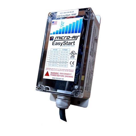
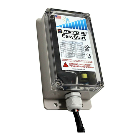
MICRO-AIR EasyStart Home User manual

©2021 Micro-Air corp. 1 rev. 1.06
EasyStart Home AC Wiring
Using Micro-Air ASY-364 or ASY-368
Contents
Safety and Warnings.....................................................................................................................................2
Installing EasyStart........................................................................................................................................3
Step 1: Identify the components ..............................................................................................................3
Step 2: Mounting the unit.........................................................................................................................3
Step 3: Identify the capacitor terminals ...................................................................................................4
Three terminal run capacitors...............................................................................................................4
Two terminal run capacitors.................................................................................................................4
Step 4: Removing start devices.................................................................................................................5
Step 5: Check for compressor monitoring systems ..................................................................................5
Step 6: Connecting the ORANGE wire.......................................................................................................5
Step 7: Connecting the BROWN wire........................................................................................................6
Step 8: Connecting the WHITE wire..........................................................................................................6
Step 9: Connecting the BLACK wire ..........................................................................................................7
Step 10: Learning ......................................................................................................................................7
Appendix 1: Compressor monitoring system changes .................................................................................8
Models without Bluetooth........................................................................................................................8
Models with Bluetooth .............................................................................................................................8
Appendix 2: Maintenance.............................................................................................................................9
Appendix 3: Additional Resources................................................................................................................9

©2021 Micro-Air corp. 2 rev. 1.06
Safety and Warnings
•AC Power can be dangerous or lethal if the proper safeguards are not understood or performed.
•If you are not sure of any aspect of this installation or proper safety when working with AC line
voltages, please seek installation by a qualified HVAC or electrical professional.
•Turn off all power to the air conditioning system before proceeding.
•Read all instructions before starting installation.
•Capacitors can store a charge and should be discharged by touching both terminals
simultaneously with an insulated screw driver. Three terminal caps should use the “C” terminal
to short each of the other two terminals.

©2021 Micro-Air corp. 3 rev. 1.06
Installing EasyStart
Step 1: Identify the components
Run capacitor
Contactor
The two components shown in figure 1 will
be used to connect your EasyStart. Locate
these components in your air conditioner before proceeding. Some compressors will have additional
components and may have a circuit board as well. Power comes in from the bottom of the contactor
usually from a breaker or fuse panel on the dwelling. This must be disconnected (Turn the breaker off)
before connecting EasyStart.
Step 2: Mounting the unit
EasyStart can be mounted on any flat surface in either a horizontal or vertical position. It can
also be mounted with the clear cover pointing up. The wire entry must face down when EasyStart is
mounted vertically.
Figure 1

©2021 Micro-Air corp. 4 rev. 1.06
Step 3: Identify the capacitor terminals
Three terminal run capacitors
HERM
FAN
C
Many compressors have three
terminal group capacitors as
shown in figure 1. These capacitors feature labels on the top as indicated by the arrows above. Use the
labels on these capacitors to identify where to make connections.
Two terminal run capacitors
Wire to contactor and capacitor
Two terminal group caps are harder to identify the terminals
because they are not labeled. Look for a wire that connects the
contactor to the capacitor like the red one shown in figure 3. This
wire is connected to the “C” terminal and will be left in place. The
other unmarked terminal is the HERM terminal. For the remainder of
this document, we will refer to the HERM terminal and C terminal for
all types of capacitors.
Figure 2
Figure 3

©2021 Micro-Air corp. 5 rev. 1.06
Step 4: Removing start devices
HERM terminal group
There is only a single yellow wire connected to the
HERM terminal in figure 4. Compressors with only one wire on
the HERM terminal have no start components and can go on to
the next step.
If you find there is more than one wire on this group,
you will need to identify which of these wires, if any, goes to a
start device.
One wire will always go to the compressor which you can verify using your factory wiring
diagram or tracing them out. One may be a compressor monitoring wire and should be preserved and is
explained in the next step. The one to remove can go to a relay, a second capacitor called a start
capacitor or a PTC device which is a small disk. Remove this start assist wire from the herm terminal at
both ends while leaving all the other HERM wires alone. If you have a PTC or hard start you can just
remove the entire device.
Step 5: Check for compressor monitoring systems
Some systems have monitoring circuit that verifies the compressor is running and provides
feedback, like a lights or fault indication, when the compressor fails to start. These systems have a
control board located in the electrical box and a fault chart located nearby that lists specific compressor
faults. If your system contains one of these control boards, you will need to remove the start delay in
EasyStart so it does not cause an artificial fault.
See Appendix 1: Compressor monitoring system changes for information on this change if it is
required for your installation.
Step 6: Connecting the ORANGE wire
Connect the EasyStart ORANGE wire to the HERM terminal.
Figure 4

©2021 Micro-Air corp. 6 rev. 1.06
Step 7: Connecting the BROWN wire
Follow the wire that connects the C terminal on the run
capacitor to the contactor. Disconnect the compressor
“R” terminal wire located on the same side of the
contactor. This wire is often a heavy gauge wire
connected to the screw part of the contactor. It may
also be on a quick connect as shown in figure 5.
Connect the disconnected wire to the BROWN wire
from EasyStart. Connect only these two wires together
and not to anything else.
Step 8: Connecting the WHITE wire
Connect the EasyStart WHITE wire to the contactor where the wire was removed from in the last step.
This is typically under the screw terminal on the contactor.
Note: Compressors with an RLA over 18 amps should not use the spade connection like shown
in figure 5 but should connect using a ring, fork or direct wire connection under the screw. Be sure to
match whatever method is used for the original installation.
Figure 5

©2021 Micro-Air corp. 7 rev. 1.06
Step 9: Connecting the BLACK wire
Contactors are “split” into two electrically separate halves with each half connected to a single voltage
line of the incoming service. The red wires are both connected to one side of the contactor in the picture
below and the black wires are connected on the other side of the contactor. The wire colors may be
different in your installation. Connect the BLACK EasyStart wire to the side of the contactor where the
EasyStart WHITE wire is NOT connected using an
available connection point.
Connect here
Step 10: Learning
Start the air conditioner on AC mains power. The fan will come on followed shortly after by the
compressor. EasyStart is now installed. The compressor can be cycled normally to complete the learning
process. If you are going to test on a generator or alternate power source, be sure the compressor has
started five times before starting on a generator or other power source.
Figure 6

©2021 Micro-Air corp. 8 rev. 1.06
Appendix 1: Compressor monitoring system changes
IMPORTANT: These instructions are not interchangeable between Bluetooth and non-Bluetooth models.
Bluetooth models should not have their cover removed and using the wrong method will not allow the
unit to function properly.
Models without Bluetooth
First place the shorting jumpers from the six-pin header on pins 1 and 3, and pins 4 and 6 as
shown below. The next step is to cut JMP2 on the circuit board. This will disable the timer and start the
compressor immediately. Your circuit board may look a little different from the image but the process is
the same on all boards.
Figure 7
Models with Bluetooth
Bluetooth models must be connected to power to disable the
starting delay before installation. Turn off the breaker to the air
conditioner. Connect the black and white EasyStart wires to the line
input side of the contactor indicated by the yellow arrows in figure 8.
Tape or wire nut the EasyStart brown and orange wire ends so they
cannot make electrical contact with anything. Turn on the breaker to
the air conditioner.
Open the smart device application on an Android or Apple
device. To start the connection, enter “EasyStart_”, including the
underscore (case sensitive), in the white box below “Enter EasyStart
Bluetooth ID:” and press return. The “Connect to EasyStart” button
will become enabled. Press the button to connect to the starter. The
screen will change to show the ID of the starter.
Click the relearn tab and slide the switch for “No pwr on
delay” to “ON”. Set the SCPT (minutes) for 1. Press “send settings to EasyStart”. Exit the app and turn off
the breaker to the air conditioner. Disconnect the white and black EasyStart wires and continue with the
installation.
Figure 8

©2021 Micro-Air corp. 9 rev. 1.06
Appendix 2: Maintenance
The box and entry are water tight and can withstand normal rain events. The box should not be
pressure washed since it is not rated for high power water jet cleaning. It can be washed with a mild
soap and water solution.
Appendix 3: Additional Resources
For additional information on EasyStart, troubleshooting or assistance, please visit our website at
www.Microair.net .
Table of contents
Other MICRO-AIR Controllers manuals
Popular Controllers manuals by other brands
GESTRA
GESTRA NRR 2-52 Original Installation & Operating Manual

Train-Tech
Train-Tech SC1 manual
Philips
Philips Dynalite Revolution Series installation instructions
Mitsubishi Electric
Mitsubishi Electric MELSEC-L Series LD40PD01 user manual
VS LIGHTING SOLUTIONS
VS LIGHTING SOLUTIONS Blu2Light MultiSensor XXL quick start guide
Phocos
Phocos MPPTsolid user manual
