Emotron MSF 2.0 User manual

Queensland Urban Utilities
CONTRACT BW 70103-029-SPR107d
Pump Station Switchboard Replacement
SP043 St Conel Street Nudgee
ELECTRICAL SWITCHBOARD
OPERATION and MAINTENANCE MANUAL
St Conel Street Nudgee SPS SP043 Electrical Switchboard Operation and Maintenance Manual (Whelan)
Q-Pulse Id TMS484
Active 03/12/2013
Page 1 of 372

Queensland Urban Utilities
INDEX
1.Soft Starters (Emotron)
2.Graphic Display (Redlion)
3.Radio (Trio)
4.Level Transducer (Endress)
5.Pressure Transducer (Vega)
6.Miscellaneous
7.Drawings
8.Test Certificate
St Conel Street Nudgee SPS SP043 Electrical Switchboard Operation and Maintenance Manual (Whelan)
Q-Pulse Id TMS484
Active 03/12/2013
Page 2 of 372

1. SOFT STARTERS
St Conel Street Nudgee SPS SP043 Electrical Switchboard Operation and Maintenance Manual (Whelan)
Q-Pulse Id TMS484
Active 03/12/2013
Page 3 of 372

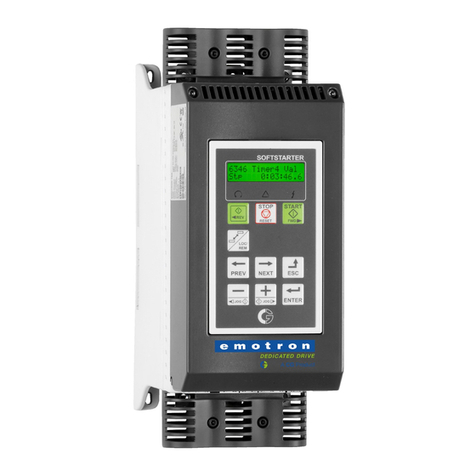
Emotron MSF 2.0
Softstarter
Instruction manual
English
St Conel Street Nudgee SPS SP043 Electrical Switchboard Operation and Maintenance Manual (Whelan)
Q-Pulse Id TMS484
Active 03/12/2013
Page 4 of 372

MSF 2.0
SOFTSTARTER
Instruction manual
Document number: 01-4135-01
Edition: r1
Date of release: 25-07-2007
© Copyright Emotron AB 2000-2007
Emotron retains the right to change specifications and illustrations in
the text, without prior notification. The contents of this document may
not be copied without the explicit permission of Emotron AB.
Valid for the following softstarter models:
MSF 2.0
St Conel Street Nudgee SPS SP043 Electrical Switchboard Operation and Maintenance Manual (Whelan)
Q-Pulse Id TMS484
Active 03/12/2013
Page 5 of 372

Emotron AB 01-4135-01r1 1
Safety instructions
Safety
The softstarter should be installed in a cabinet or in an
electrical control room.
• The device must be installed by trained personnel.
• Disconnect all power sources before servicing.
• Always use standard commercial fuses, slow blow e.g. gl,
gG types, to protect the wiring and prevent short
circuiting. To protect the thyristors against short-circuit
currents, superfast semiconductor fuses can be used if
preferred. The normal guarantee is valid even if superfast
semiconductor fuses are not used.
Operating and maintenance
personnel
1. Read the whole Instruction Manual before install-
ing and putting the equipment into operation.
2. During all work (operation, maintenance, repairs,
etc.) observe the switch-off procedures given in this
instruction as well as any other operating
instruction for the driven machine or system. See
Emergency below.
3. The operator must avoid any working methods
which reduce the safety of the device.
4. The operator must do what he can to ensure that
no unauthorised person is working on the device.
5. The operator must immediately report any changes
to the device which reduce its safety to the user.
6. The user must undertake all necessary measures to
operate the device in perfect condition only.
Installation of spare parts
We expressly point out that any spare parts and acces-
sories not supplied by us have also not been tested or
approved by us.
Installing and/or using such products can have a nega-
tive effect on the characteristics designed for your
device. The manufacturer is not liable for damage aris-
ing as a result of using non-original parts and accesso-
ries.
Emergency
You can switch the device off at any time with the
mains switch connected before the softstarter (both
motor and control supply voltage must be switched
off).
Dismantling and scrapping
The enclosure of the softstarter is made of recyclable
material such as aluminium, iron and plastic. Legal
requirements for disposal and recycling of these materi-
als must be complied with.
The softstarter contains a number of components
demanding special treatment, such as thyristors for
example. The circuit boards contain small amounts of
tin and lead. Legal requirements for the disposal and
recycling of these materials must be complied with.
General warnings
WARNING! Make sure that all safety measures
have been taken before starting the motor in
order to avoid personal injury.
WARNING! Never operate the softstarter with
the front cover removed.
WARNING! Make sure that all safety measures
have been taken before switching on the power
supply.
!
!
!
St Conel Street Nudgee SPS SP043 Electrical Switchboard Operation and Maintenance Manual (Whelan)
Q-Pulse Id TMS484
Active 03/12/2013
Page 6 of 372

2Emotron AB 01-4135-01r1
St Conel Street Nudgee SPS SP043 Electrical Switchboard Operation and Maintenance Manual (Whelan)
Q-Pulse Id TMS484
Active 03/12/2013
Page 7 of 372

Emotron AB 01-4135-01r1 3
Contents
1. General information ....................................... 5
1.1 How to use the Instruction Manual.......................... 5
1.2 Integrated safety systems ........................................ 5
1.3 Safety measures ....................................................... 5
1.4 Notes to the Instruction Manual .............................. 5
1.5 Type number.............................................................. 5
1.6 Standards .................................................................. 6
1.7 Tests in accordance with norm EN 60204
standard..................................................................... 6
1.8 Transport and packing.............................................. 6
1.9 Unpacking MSF-310 and larger types ..................... 6
1.10 Glossary ..................................................................... 7
2. Description...................................................... 9
2.1 Background theory.................................................... 9
2.2 Reduced voltage starting........................................ 10
2.3 Other starting methods........................................... 12
2.4 Use of softstarters with torque control .................. 13
3. Mounting ...................................................... 15
3.1 Installation of the softstarter in a cabinet............. 15
4. Connections ................................................. 19
4.1 Connecting mains and motor cables ..................... 20
4.2 Control Connection ................................................. 24
4.3 Minimum wiring....................................................... 25
4.4 Wiring examples ...................................................... 25
5. How to get started....................................... 27
5.1 Checklist .................................................................. 27
5.2 Applications ............................................................. 27
5.3 Motor data ............................................................... 28
5.4 Start and stop.......................................................... 28
5.5 Setting the start command..................................... 29
5.6 Viewing the motor current ...................................... 29
5.7 Starting .................................................................... 29
6. Applications and functions selection ........ 31
6.1 Softstarter rating according to AC53a ................... 31
6.2 Softstarter rating according to AC53b ................... 31
6.3 The Applications Rating List ................................... 32
6.4 The Application Functions List ............................... 34
6.5 Special conditions ................................................... 36
7. Operation of the softstarter........................ 39
7.1 General description of user interface .................... 39
7.2 Control panel ........................................................... 39
7.3 LED indication ......................................................... 40
7.4 The menu structure................................................. 40
7.5 The keys................................................................... 40
7.6 Control panel lock ................................................... 41
7.7 Overview of softstarter operation and parameter set-
up ............................................................................. 42
8. Functional description................................. 43
8.1 General settings ...................................................... 44
8.2 Motor data ............................................................... 45
8.3 Motor protection...................................................... 46
8.4 Parameter set handling .......................................... 51
8.5 Autoreset ................................................................. 52
8.6 Serial communication ............................................. 54
8.7 Operation settings................................................... 55
8.8 Process protection .................................................. 69
8.9 I/O settings .............................................................. 77
8.10 View operation......................................................... 91
8.11 Alarm list .................................................................. 94
8.12 Softstarter data ....................................................... 95
9. Protection and alarm ................................... 97
9.1 Alarm codes............................................................. 97
9.2 Alarm actions........................................................... 97
9.3 Reset........................................................................ 97
9.4 Alarm overview ........................................................ 98
10. Troubleshooting ......................................... 101
10.1 Fault, cause and solution ..................................... 101
11. Maintenance .............................................. 105
11.1 Regular maintenance ........................................... 105
12. Options........................................................ 107
12.1 Serial communication........................................... 107
12.2 Fieldbus systems................................................... 107
12.3 External control panel........................................... 107
12.4 Terminal clamp...................................................... 108
13. Technical data............................................ 109
13.1 Electrical specifications ........................................ 109
13.2 General electrical specifications.......................... 114
13.3 Fuses and power losses ....................................... 115
13.4 Mechanical specifications including mechanical
drawings ................................................................ 116
13.5 Derating at higher temperature ........................... 117
13.6 Environmental conditions..................................... 117
13.7 Standards .............................................................. 117
13.8 Power- and signal connectors. ............................. 118
13.9 Semi-conductor fuses ........................................... 119
14. Set-up menu list ......................................... 121
St Conel Street Nudgee SPS SP043 Electrical Switchboard Operation and Maintenance Manual (Whelan)
Q-Pulse Id TMS484
Active 03/12/2013
Page 8 of 372

4Emotron AB 01-4135-01r1
St Conel Street Nudgee SPS SP043 Electrical Switchboard Operation and Maintenance Manual (Whelan)
Q-Pulse Id TMS484
Active 03/12/2013
Page 9 of 372

Emotron AB 01-4135-01r1 General information 5
1. General information
This manual describes the Emotron Softstarter MSF 2.0.
1.1 How to use the Instruction
Manual
This instruction manual tells you how to install and operate
the softstarter MSF 2.0. Read the whole Instruction Manual
before installing and putting the unit into operation.
Once you are familiar with the softstarter, you can operate it
from the control panel by referring to chapter 5. page 27.
This chapter describes all the functions and possible settings.
1.2 Integrated safety systems
The device is equipped with a protection system which
reacts to:
• Over temperature
• Voltage unbalance
• Over- and under voltage
•Phasereversal
• Phase loss
• Motor overload protection thermal and PTC.
• Motor load monitor, protecting machine or process
maximum or minimum alarm
• Starts per hour limitation
The softstarter is equipped with a connection for protective
earth (PE).
All MSF 2.0 softstarters are IP 20 enclosed types, except
MSF-1000 and MSF-1400 which are delivered as open
chassis IP00.
1.3 Safety measures
These instructions are a constituent part of the device and
must be:
• Available to competent personnel at all times.
• Read prior to installation of the device.
• Observed with regard to safety, warnings and informa-
tion given.
The tasks in these instructions are described so that they can
be understood by people trained in electrical engineering.
Such personnel must have appropriate tools and testing
instruments available. Such personnel must have been
trained in safe working methods.
The safety measures laid down in DIN standard VDE 0100
must be guaranteed.
The user must obtain any general and local operating per-
mits and meet any requirements regarding:
• Personnel safety
•Productdisposal
• Environmental protection
1.4 Notes to the Instruction
Manual
Important
For all enquiries and spare parts orders, please quote the cor-
rect name of the device and serial number to ensure that
your inquiry or order is dealt with correctly and swiftly.
1.5 Type number
Fig. 1, page 5 gives an example of the type code number
used for an Emotron MSF Softstarter. With this code
number the exact type of the softstarter can be determined.
This identification will be required for type specific informa-
tion when mounting and installing. The code number is
located on the product label, on the front of the unit.
Fig. 1 Type number.
NOTE! The safety measures must remain in force at all
times. Should questions or uncertainties arise, please
contact your local sales outlet.
NOTE: Additional information as an aid to avoiding
problems.
CAUTION: Failure to follow these instructions
can result in malfunction or damage to the
softstarter.
WARNING: Failure to follow these instructions
can result in serious injury to the user in addition
to serious damage to the softstarter.
MSF -017 525 2 C V N
1234567
!
St Conel Street Nudgee SPS SP043 Electrical Switchboard Operation and Maintenance Manual (Whelan)
Q-Pulse Id TMS484
Active 03/12/2013
Page 10 of 372

6 General information Emotron AB 01-4135-01r1
1.6 Standards
The device is manufactured in accordance with these regula-
tions:
• IEC 60947-4-2
• EN 60204-1, Safety of Machinery, Electrical equipment
of machines, part 1, General requirements and VDE
0113.
• EN 61000-6-4, EMC, Emission standard for industrial
environments
• EN 61000-6-3, EMC, Emission standard for residential,
commercial and light-industrial environments
• EN 61000-6-2, EMC, Immunity for industrial environ-
ments
•GOST
•UL508
1.7 Tests in accordance with
norm EN 60204 standard
Before leaving the factory, the device was subjected to the
following tests:
• Through connection of earthing system:
a) visual inspection.
b) check that earthing wire is firmly connected.
• Insulation
•Voltage
• Function
1.8 Transport and packing
The device is packed in a carton or plywood box for delivery.
The outer packaging can be recycled. The devices are care-
fully checked and packed before dispatch, but transport
damage cannot be ruled out.
Check on receipt
Check that the goods are complete as listed on the delivery
note, see type no. etc. on the rating plate.
Is the packaging damaged?
Check the goods for damage (visual check).
If you have cause for complaint
If the goods have been damaged during transport:
• Contact the transport company or the supplier immedi-
ately.
• Keep the packaging (for inspection by the transport
company or for returning the device).
Packaging for returning the device
Pack the device so that it will resist shock and impact.
Intermediate storage
After delivery or after it has been dismounted, the device can
be stored before further use in a dry room.
1.9 Unpacking MSF-310 and
larger types
The MSF 2.0 softstarter is attached to the plywood box/
loading stool by screws, and the softstarter must be
unpacked as follows:
1. Open only the securing plates at the bottom of the box
(bend downwards). Then lift up the box from the load-
ing stool, both top and sides in one piece.
2. Loosen the three (3) screws on the front cover of the
softstarter unit, down by the lower logo.
3. Push up the front cover about 20 mm so that the front
cover can be removed.
4. Remove the two (2) mounting screws at the bottom of
the softstarter.
5. Lift up the softstarter unit at the bottom about 10 mm
and then push backwards about 20 mm so that the soft-
starter can be removed from the mounting hooks* at the
top. The hooks are placed under the bottom plate and
cannot be removed until the softstarter is pulled out.
6. Loosen the two screws (2) for the mounting hooks and
remove the hooks.
7. The hooks are used as an upper support for mounting
the softstarter.
Ta b l e 1
Position Configuration
parameter Description
1 Softstarter type MSF 2.0 type, Fixed
2 Motor current 017-1400 A
3Mains supply
voltage
525 V
690 V
4Control supply
voltage
2=100-240 V
5=380-500 V
5Control panel
option
C=Standard, no external
control panel
H=External control panel
6Coated boards
option
-=No coated boards
V=Coated boards
7Communication
option
N=No COM included
S=RS232/485 included
D=DeviceNet included
P=Profibus included
St Conel Street Nudgee SPS SP043 Electrical Switchboard Operation and Maintenance Manual (Whelan)
Q-Pulse Id TMS484
Active 03/12/2013
Page 11 of 372

Emotron AB 01-4135-01r1 General information 7
Fig. 2 Unpacking MSF-310 and larger models.
1.10 Glossary
1.10.1 Abbreviations
In this manual the following abbreviations are used:
1.10.2Definitions
In this manual the following definitions for current, voltage,
power, torque and speed are used:
Table 2 Abbreviations
Abbreviation Description
FLC Full load current
DOL Direct on-line
Table 3 Definitions
Name Description Unit
Insoft Nominal softstarter current A
Pnsoft Nominal softstarter power kW, HP
Nnsoft Nominal softstarter speed rpm
TnNominal motor torque Nm, lbft
UnNominal motor voltage V
InNominal motor current A
PnNominal motor power kw, HP
Pnormal Normal load % of Pn
St Conel Street Nudgee SPS SP043 Electrical Switchboard Operation and Maintenance Manual (Whelan)
Q-Pulse Id TMS484
Active 03/12/2013
Page 12 of 372

8 General information Emotron AB 01-4135-01r1
St Conel Street Nudgee SPS SP043 Electrical Switchboard Operation and Maintenance Manual (Whelan)
Q-Pulse Id TMS484
Active 03/12/2013
Page 13 of 372

Emotron AB 01-4135-01r1 Description 9
2. Description
In this chapter different starting methods for induction
motors are explained and compared. The functionality of
softstarters with torque control and their advantages and
limitations compared to other starting methods are
explained.
First a brief account of the background theory of starting
induction motors will be given in section 2.1. Thereafter the
different starting methods based on the usage of reduced
voltage will be described and compared. This chapter will
also cover softstarters with torque control. In section 2.3
some common starting methods based on other physical
principles are explained. With this information some limita-
tions of the reduced voltage starters will become clear. In
section 2.4 there is a brief analysis of which applications may
benefit from using a softstarter.
2.1 Background theory
The following two sections deal with motors with squirrel-
cage rotors. In contrast to a wound rotor, the squirrel-cage
rotor consists of straight conductors, which are short-
circuited together at both ends.
When such a motor is connected directly to the line voltage
it will typically draw a starting current of about 5 to 8 times
its nominal current while the resulting starting torque will
be about 0.5 to 1.5 times its nominal torque. In the follow-
ing picture a typical starting characteristic is shown. The x-
axis represents the speed relative to the nominal speed while
the y-axis shows the torque and the current respectively, even
those normalized to their nominal values. The dashed line
indicates the nominal values.
Fig. 3 Typical torque characteristics for the DOL start
Fig. 4 Typical current characteristics for the DOL start
For many industrial applications direct on-line starting is
not convenient, as the supply in this case has to be dimen-
sioned to deliver the unnecessarily high starting current.
Moreover, most applications do not gain anything from the
high starting torque. Instead there is a risk of mechanical
wear or even damage because of the resulting jerk at spee-
dup.
The acceleration torque is determined by the difference
between motor and load torque. The figure below shows
some typical torque characteristics for constant speed appli-
cations. For comparative purposes, the inducion motors’
torque characteristic is added to the diagram.
Fig. 5 Typical load torque characteristics
Typical applications with constant load are elevators, cranes
and conveyors. Linear load characteristics are found for cal-
endar rollers and smoothing machines; quadratic correlation
between speed and torque is typical for pumps and fans.
0
0.5
1
1.5
2
2.5
00.51
Torque
T/Tn
n/nn
0
1
2
3
4
5
6
7
8
00.51
Current
I/In
n/nn
0
0.5
1
1.5
2
2.5
0 0.5 1
Torque
T/Tn
n/nn
St Conel Street Nudgee SPS SP043 Electrical Switchboard Operation and Maintenance Manual (Whelan)
Q-Pulse Id TMS484
Active 03/12/2013
Page 14 of 372

10 Description Emotron AB 01-4135-01r1
Some applications like conveyors or screws may need an ini-
tial torque boost. However, for many applications it can be
seen that the torque needed is much lower than the torque
delivered by the induction motor in a DOL start.
A common method to reduce both starting torque and cur-
rent is to decrease the motor voltage during starting. The
following figure shows how the motor’s torque and current
characteristics are changed when the supply voltage is
reduced.
Fig. 6 Reduced voltage start
A general rule of thumb is that the torque at each operating
point is roughly proportional to the square of the current.
This means when the motor current is decreased by a factor
of two by means of reducing the supply voltage, the torque
delivered by the motor will be decreased by a factor of four
(approximately).
This relationship is the base for any starting method using
reduced voltage. It can be seen that the possibility of reduc-
ing the starting current depends on the correlation between
the motor’s and the load’s torque characteristic. For the com-
bination of an application with very low starting load and a
motor with very high starting torque, the starting current
may be reduced significantly by means of decreasing the
voltage during start. However, for applications with high
starting load it may – depending on the actual motor – not
be possible to reduce the starting current at all.
2.2 Reduced voltage starting
This section describes different starting methods which are
based on the reduced-voltage principle explained above. A
pump and its quadratic torque characteristic are used as an
example.
The star-delta starter is the simplest example of a reduced
voltage starter. The motor phases are first star connected; at
about 75% of nominal speed the phase connection is then
changed to delta. To enable star-delta start, both ends of all
three motor windings have to be available for connection.
Moreover, the motor has to be dimensioned for the (higher)
voltage in the delta connection. The following figure shows
the resulting torque and current characteristics.
Fig. 7 Star-delta start
0
1
2
3
4
5
6
7
8
00.51
0
0.5
1
1.5
2
2.5
00.51
Torque
T/Tn
n/nn
Current
I/In
n/nn
Un
U2<Un
U3<U2
Un
U2<Un
U3<U2
T ~ I 2
ILV = 1/2 IDOL -> TLV ≈1/4 TDOL
ILV = 1/3 IDOL -> TLV ≈1/9 TDOL
LV=low voltage
DOL=Direct on line
0
1
2
3
4
5
6
7
8
00.51
I/In
n/nn
0
0.5
1
1.5
2
2..5
00.51
Torque
T/Tn
n/nn
Current
St Conel Street Nudgee SPS SP043 Electrical Switchboard Operation and Maintenance Manual (Whelan)
Q-Pulse Id TMS484
Active 03/12/2013
Page 15 of 372

Emotron AB 01-4135-01r1 Description 11
The disadvantage of the star-delta start is that it cannot be
adapted to a special application. Both the voltage in star and
in delta connection are defined by the supply, the resulting
starting performance depends on the motor’s DOL charac-
teristic. For some applications the star-delta starter cannot
be used as the resulting torque in star connection is too low
to start rotating the load. On the other hand for low load
applications further savings of starting current are impossi-
ble even though a big torque reserve is available. Moreover,
the resulting abrupt rise of torque first at start and later
when changing from star to delta connection may contrib-
ute to mechanical wear. The high transient currents during
start-delta transition create unnecessary excess heat in the
motor.
Better performance is achieved with a voltage ramp start,
which a simple electronic softstarter can provide. The volt-
age is increased linearly from an initial value to the full sup-
ply voltage by means of phase angle control. The resulting
torque and current characteristics are shown in the following
figure.
Fig. 8 Soft starting – voltage ramp
Obviously a much smoother start is realized compared to the
star-delta start and the starting current is decreased.
A softstarter i often used to keep the starting current below a
desired level. For the example above, setting a current limit
of three times the nominal current may be desirable. The
following figure shows the resulting torque and current char-
acteristics.
Fig. 9 Soft starting – voltage ramp with current limit
Once again the figure illustrates that the resulting perform-
ance depends on the combination of motor and load charac-
teristics. In the example above the motor torque is close to
the load torque at about half speed. This means for some
other applications with different load characteristics (for
example a linear torque-speed correlation) this particular
motor would need more than three times the nominal cur-
rent to start.
The most sophisticated electronic softstarters use torque
control, which results in an almost constant acceleration
during the start. A low starting current is also achieved.
However, even this start method uses reduced motor voltage
and the quadratic correlation between current and torque
described in the first section of this chapter is still valid. This
means, the lowest possible starting current is determined by
the combination of motor and load characteristics.
0
1
2
3
4
5
6
7
8
00.51
0
0.5
1
1.5
2
2.5
00.51
I/In
n/nn
Torque
T/Tn
n/nn
Current
0
1
2
3
4
5
6
7
8
00.51
0
0.5
1
1.5
2
2.5
00.51
I/In
n/nn
Torque
T/Tn
n/nn
Current
St Conel Street Nudgee SPS SP043 Electrical Switchboard Operation and Maintenance Manual (Whelan)
Q-Pulse Id TMS484
Active 03/12/2013
Page 16 of 372

12 Description Emotron AB 01-4135-01r1
Fig. 10 Soft starting – torque control
For optimal starting performance, correct setting of the soft-
starter’s parameters such as initial torque and end torque at
start and start time is important. The choice of parameters is
explained in detail in section 8.7, page 55.
2.3 Other starting methods
In contrast to the preceding sections of this chapter, which
focused on squirrel-cage motors, slip-ring motors are dealt
with later on. A slip-ring motor is equipped with a wound
rotor; one end of each rotor winding is available for external
connection via slip-rings. These motors are often optimized
for rotor resistance starting, e.g. with short-circuited rotor
windings they develop a very low torque at an extremely
high current. For starting external resistances are connected
to the rotor windings. During the start, the resistance value
is decreased in several steps until the rotor windings are
short-circuited at nominal speed. The following figure
shows typical torque and current characteristics for a slip-
ring motor during the start with an external rotor-resistance
starter.
Fig. 11 Rotor-resistance starting
Because of the low starting torque it is often not possible to
short-circuit the rotor windings and replace the rotor-resist-
ance starter with a softstarter. However, it is always possible
to use a frequency inverter instead. The following illustra-
tion shows how the torque and current characteristics are
affected when the stator frequency is changed.
0
1
2
3
4
5
6
7
8
00.51
0
0.5
1
1.5
2
2.5
00.51
I/In
n/nn
Torque
T/Tn
n/nn
Current
0
1
2
3
4
5
6
7
8
00.51
0
0.5
1
1.5
2
2.5
00.51
I/IN
n/nn
Torque
T/Tn
n/nn
Current
St Conel Street Nudgee SPS SP043 Electrical Switchboard Operation and Maintenance Manual (Whelan)
Q-Pulse Id TMS484
Active 03/12/2013
Page 17 of 372

Emotron AB 01-4135-01r1 Description 13
Fig. 12 Voltage/frequency regulation
Thus, such a motor can be started with a quite simple fre-
quency inverter with voltage-frequency regulation. This
solution is even valid for all other applications, which for
some reason (high load torque compared to motor torque
etc.) cannot be started by a softstarter.
2.4 Use of softstarters with
torque control
To determine if a specific application benefits from using a
softstarter at all, the correlation between the motor’s torque
characteristic during the start and the load’s requirements
has to be evaluated. As it can be seen from the examples
above, the application will only benefit from using a soft-
starter if the load torque during the start is clearly below the
motor’s starting capacity. However, even loads with a high
initial release torque may profit from a softstarter. In this
case an initial torque boost can be used, thereafter the start
ramp is continued reducing the starting current considera-
bly.
The profit can be maximized when using a softstarter with
torque control. To be able to configure the torque control
parameters for optimal performance, the load characteristics
(linear, square or constant load, need of initial release
torque) must be known. In this case a proper torque control
method (linear or square) can be chosen and torque boost
can be enabled if needed. A description of the load charac-
teristics of several common applications and guidelines for
proper settings are found in chapter 6. page 31, Applications
and Functions Selection. Optimization of the torque control
parameter is explained in detail in section 8.7, page 55.
0
1
2
3
4
5
6
7
8
00.51
0
0.5
1
1.5
2
2.5
00.51
I/In
n/nn
Torque
T/Tn
n/nn
Current
f3<f2f2<fnfn
f3<f2f2<fnfn
St Conel Street Nudgee SPS SP043 Electrical Switchboard Operation and Maintenance Manual (Whelan)
Q-Pulse Id TMS484
Active 03/12/2013
Page 18 of 372

14 Description Emotron AB 01-4135-01r1
St Conel Street Nudgee SPS SP043 Electrical Switchboard Operation and Maintenance Manual (Whelan)
Q-Pulse Id TMS484
Active 03/12/2013
Page 19 of 372

Emotron AB 01-4135-01r1 Mounting 15
3. Mounting
This chapter describes how to mount the MSF 2.0 soft-
starter. Before mounting it is recommended that the installa-
tion be planned out first:
• Be sure that the softstarter suits the mounting location.
• The mounting site must support the weight of the soft-
starter.
• Will the softstarter continuously withstand vibrations
and/or shocks?
• Consider using a vibration damper.
• Check ambient conditions, ratings, required cooling air
flow, compatibility of the motor, etc.
• Do you know how the softstarter will be lifted and trans-
ported?
Make sure that the installation is performed in accordance
with the local safety regulations of the electricity supply
company. And in accordance with DIN VDE 0100 for set-
ting up heavy current plants.
Care must be taken to ensure that personnel do not come
into contact with live circuit components.
3.1 Installation of the
softstarter in a cabinet
When installing the softstarter:
• Ensure that the cabinet will be sufficiently ventilated
after the installation.
• Keep the minimum free space, see the tables on page 15.
• Ensure that air can flow freely from the bottom to the
top.
MSF-017 to MSF-835 are all delivered as enclosed versions
with front opening. The units have bottom entry for cables
etc. see Fig. 20 on page 21 and Fig. 22 on page 23. MSF-
1000 and MSF-1400 are delivered as open chassis.
3.1.1 Cooling
MSF-017 to MSF-250
MSF-310 to MSF-1400
WARNING! Never operate the softstarter with
the front cover removed.
NOTE: When installing the softstarter, make sure it does
not come into contact with live components. The heat
generated must be dispersed via the cooling fins to
prevent damage to the thyristors (free circulation of air).
Table 4 MSF-017 to MSF-250
MSF
model
Minimum free space (mm):
above 1) below at side
-017, -030, -045 100 100 0
-060, -075, -085 100 100 0
-110, -145 100 100 0
-170, -210, -250 100 100 0
1) Above: wall-softstarter or softstarter-softstarter
Table 5 MSF-310 to MSF-1400.
MSF
model
Minimum free space (mm):
above 1) below at side
-310, -370, -450 100 100 0
-570, -710, -835 100 100 0
-1000, -1400 100 100 100
1) Above: Wall-softstarter or softstarter-softstarter
St Conel Street Nudgee SPS SP043 Electrical Switchboard Operation and Maintenance Manual (Whelan)
Q-Pulse Id TMS484
Active 03/12/2013
Page 20 of 372
Table of contents
Other Emotron Controllers manuals
Popular Controllers manuals by other brands

Grundfos
Grundfos CMB-SP PM1 instructions

Zeck Audio
Zeck Audio FOCUS 20CT Service manual

Native Instruments
Native Instruments komplete kontrol s series manual

Smartgen
Smartgen HAT880 Series user manual

Full Gauge Controls
Full Gauge Controls RCK-862 plus manual

Mitsubishi Electric
Mitsubishi Electric RD62P2E Application User's Manual