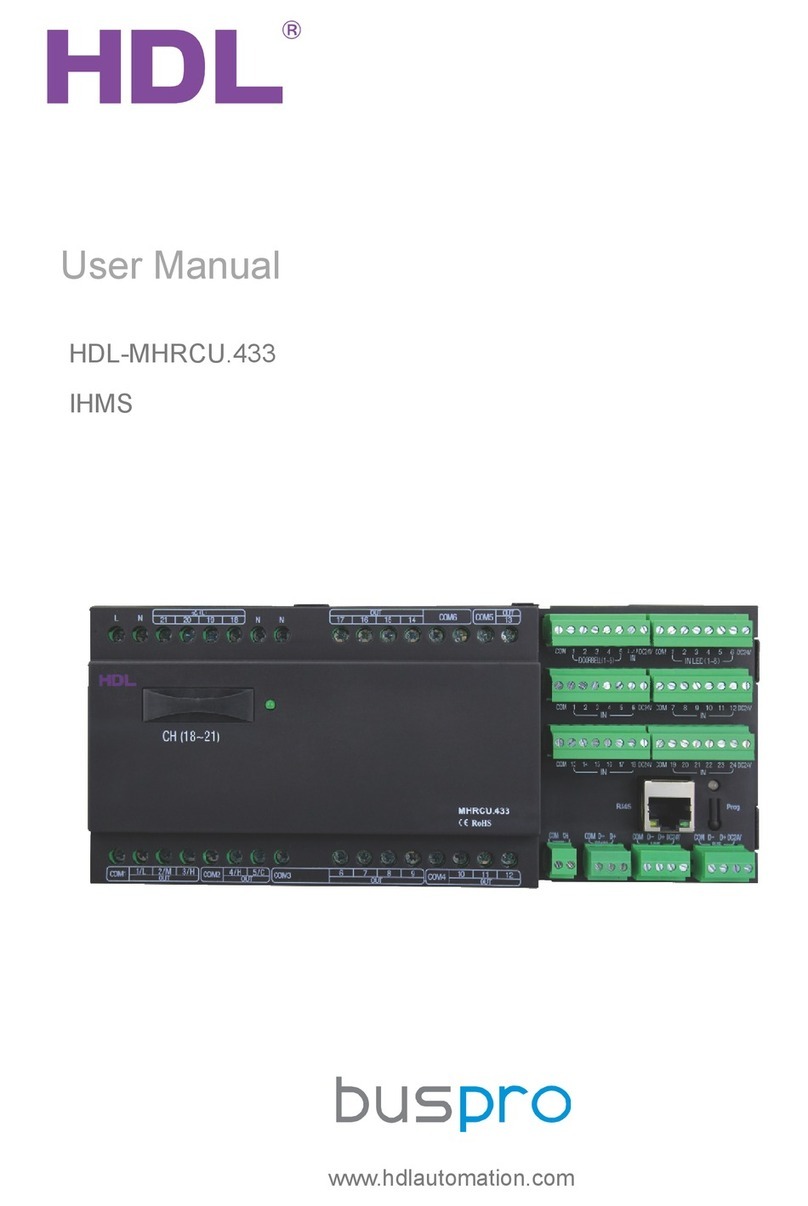
Buspro HDL SB-DN-HVAC User manual

User Manual
SB-DN-MAC01.331
HVAC Controller – User Manual
Document updates:
Version
Data
Description
V1.0
2015.05.25
Finish new document

User Manual
SB-DN-MAC01.331
HVAC Controller – User Manual
INDEX
1. Overview........................................................................................................................................1
2. Main Functions............................................................................................................................. 1
3. Basic Parameters.........................................................................................................................1
4. Dimensions and specifications.................................................................................................. 2
4.1 Dimensions......................................................................................................................... 2
4.2 Device Description.............................................................................................................3
4.3 Precautions.........................................................................................................................3
5. Wiring............................................................................................................................................. 4
5.1 Wiring Diagram.................................................................................................................. 4
5.2 HDL Buspro Description................................................................................................... 4
5.3 Commissioning...................................................................................................................5
6. Software Configuration............................................................................................................... 5
6.1 Basic Information............................................................................................................... 5
6.1.1 Changing the device ID.........................................................................................6
6.1.2 Remark.....................................................................................................................6
6.2 Settings................................................................................................................................6
6.2.1 Testing the wiring....................................................................................................7
6.2.2 Air-conditioner delay settings............................................................................... 7
6.2.3 AC model configuration......................................................................................... 8
6.2.4 VAV fan voltage settings..................................................................................... 10
6.3 Air conditioning control....................................................................................................11
6.3.1 Operating modes..................................................................................................11
6.3.2 Temperature sensor settings.............................................................................. 11
6.3.3 Host settings......................................................................................................... 12
6.3.4 Mode and status configuration.......................................................................... 13
6.4 Configuring the DLP........................................................................................................14
6.4.1 Basic Information................................................................................................. 15
6.4.2 Testing and control...............................................................................................15
6.4.3 Slave information................................................................................................. 16
6.4.4 Synchronized control...........................................................................................16
6.4.5 Additional functions..............................................................................................17
7. FAQ.............................................................................................................................................. 21
8 Note...............................................................................................................................................23

User Manual
SB-DN-MAC01.331
HVAC Controller – User Manual 1
1. Overview
The SB-DN-HVAC (MAC01.31) is a centralized HVAC or FCU control module. Using a
HDL panel(with air conditioning function) and its built in smart algorithms, temperature
and fan speed settings can be changed and controlled.
2. Main Functions
Triple relays to control cooling, heating, and humidification.
Triple relays to control low, medium, and high fan speeds.
A smart control algorithm can control an air-conditioner efficiently.
Four HDL DS18B20 digital temperature sensors can be connected to the module.
One master module can control eight slave modules.
Online upgrading is supported.
3. Basic Parameters
Electric Parameters:
BUS power supply
DC15-30V
BUS power consumption
95mA/DC24V
Maximum current per CH
2A
Relay life time
60000
Environmental Conditions:
Working temperature
0℃~45℃
Working relative humidity
Up to 90%
Storage temperature
-20℃~+60℃
Storage relative humidity
Up to 93%
Approved
CE

User Manual
SB-DN-MAC01.331
HVAC Controller – User Manual 2
RoHS
Production Information:
Dimensions
72×90×66 (mm)
Weight
240.5(g)
Housing material
Nylon, PC
Installation
35mm DIN rail installation
Protection degree
IP20
4. Dimensions and specifications
4.1 Dimensions
DB box Installation

User Manual
SB-DN-MAC01.331
HVAC Controller – User Manual 3
4.2 Device Description
a) Relay 1,2,3 for mode connection
b) H,M and L=connect to Fan motor , COM2=AC220-240V
c) Manual control button for mode and fan speed.
d) Programming button.
e) DC0-10V for fan control, and digital temperature sensor input port.
f) F,G,H,I and J are HDL Buspro interface.
4.3 Precautions
HVAC systems draw large amounts of electricity when in use, which means that improper
installation can result in a risk of electrical fires, shocks and short circuits. Some states
have specific building codes that govern HVAC systems, including their wiring. Electrical
codes also apply to HVAC wiring and require electricians and builders to use wires and
devices that are compliant and safe.
Safety Precautions
It is recommended that the power input be connected to a MCB, or suitable fuse.
When installing the module do not exceed a tightening torque of 0.4Nm.
The power cable(relay output) should be:0.75mm2to 2.5mm2wire.
The module should be mounted inside a distribution box.
Care should be taken when connected the module to the Bus interface.

User Manual
SB-DN-MAC01.331
HVAC Controller – User Manual 4
Do not let the module come into contact with water.
Do not connect the Bus wire to a AC220V supply.
Ensure that the valve matches the input voltage.
Ensure that the fan you wish to control uses a power supply of AC 0-10 volts.
5. Wiring
5.1 Wiring Diagram
The wiring diagram shown below must be followed exactly.
5.2 HDL Buspro Description
Connector info
Buspro
DC24V
Red
COM
Black
DATA -
White
DATA +
Yellow

User Manual
SB-DN-MAC01.331
HVAC Controller – User Manual 5
5.3 Commissioning
Method One:
1. Run the HDL-BUS Pro Setup tool.
2. On the module long press the “programming button” for three seconds until the LED
turns red.
3. Using the software, click “Address management”, and then select “Modify address”, the
window below will then be displayed.
4. Click on “Indicate initial address”, and the current subnet/device ID of the device will
then be displayed. To modify the address, fill in the new address, and click the “Modify
initial address” then click the “+Add” button. The device will now be added to the “ON-line
devices list”.
Method Two:
1- Run the HDL-bus pro tool.
2- Search for online devices by clicking the search button, any online device will then be
displayed in the “online device list”.
6. Software Configuration
The module can be controlled via a HDL DLP panel; because of this, both the HVAC
module configuration will be explained as well the configuration of the DLP.
6.1 Basic Information
The basic settings tab displays the basic device settings and information.

User Manual
SB-DN-MAC01.331
HVAC Controller – User Manual 6
6.1.1 Changing the device ID
Each HDL device has a unique Subnet and Device ID number, each module’s Device ID
must be different from other devices on the same Bus. The Subnet ID should be the same
as the HDL-Bus gateway (typically the SB-DN-1IP or HDL-MBUS01IP.431).
6.1.2 Remark
It is recommended that the module be named as this will aid module identification in
complex installations.
6.2 Settings
The settings tab is the central location in which the module can be configured from:

User Manual
SB-DN-MAC01.331
HVAC Controller – User Manual 7
6.2.1 Testing the wiring
The wiring test ensures that every relay has been wired correctly, and that the system can
operate safely. Before programming the end-user panel, the relay wiring should be tested.
Steps: To test the wiring of this module a user should follow the below steps:
a) On the “Settings” tab tick the “Model of test relay enable” option, the test mode will
then be activated.
b) The status of each relay can be read by clicking on the “read” button.
c) Click the “set” tab to test each relay.
6.2.2 Air-conditioner delay settings
The compressor delay function serves to safeguard the HVAC module, because of this it
is recommended that the function be activated. To set these delay times, please refer to
the manual of FCU manufacturer.

User Manual
SB-DN-MAC01.331
HVAC Controller – User Manual 8
6.2.3 AC model configuration
1) Mode Selection
The air conditioner settings can be configured in two ways:
a) Normal Mode: This mode is the default mode and corresponds to the module’s default
wiring diagram, below is the normal wiring method for this module:
Default wiring: Relay-1=Cooling, Relay-2=Heating, Relay-3=Dehumidification.
b) Complex Mode: This mode is only used when the default wiring method is not used.
If for example relay#1&relay#2 is heating, relay#2 is dehumidification and relay#3 is
cooling, then the below steps should be followed:
1) Select Complex mode
2) Double click on the “HVAC settings” table to modify the settings, and change the
settings in the pop-up window.

User Manual
SB-DN-MAC01.331
HVAC Controller – User Manual 9
Relay power restore:
If this tab is selected the module will save each mode status before being powered off,
and implement them when powered on.
This function is only available in the relay mode, as the screen shot below shows.
2) Compressor Protection
Compressor protection will stop the air conditioner operating after a set period of time.
The compressor work time is how long the AC will operate before it enters into protection
mode, the compressor protect time is how long the AC will remain in the protection mode.
For example: If we set the compressor time for 120 minutes and the compressor protect
time for 10minutes, then after the compressor is used continuously for 120 minutes it will
stop and then restart after 10 minutes has elapsed.

User Manual
SB-DN-MAC01.331
HVAC Controller – User Manual 10
6.2.4 VAV fan voltage settings
The VAV fan settings allow the fan voltage to be controlled, the fan speed will increase
with a voltage increase, and vice versa.
Note:
Different parameters can be set for each fan, the minimum voltage available is 0V and the
maximum is 10V. To set the voltage value for each fan, please refer to the manual of FCU
manufacturer.
For auto wind, there are two options: 3 step and stepless(firmware version:HDL_V03.08U
_2015/01/20). If stepless is selected, the 0-10V output varies continuously according to
the temperature difference between desired temperature and room temperature.

User Manual
SB-DN-MAC01.331
HVAC Controller – User Manual 11
6.3 Air conditioning control
6.3.1 Operating modes
There are two different operating modes are available.
a) Fully control: When the ‘Fully control’ option is selected, the module has the ability to
control itself and be controlled directly from the i-Life application.
b) Slave control: When the slave mode is selected, the module can only be controlled via
a DLP, other devices(e.g. i-Life) can only control HVAC through the DLP.
6.3.2 Temperature sensor settings
The module can support 4 temperature sensors, the temperature readings can be
received in two ways:

User Manual
SB-DN-MAC01.331
HVAC Controller – User Manual 12
a) Refer to inside sensor: When this option is selected the module will receive the
temperature readings from local sensors which are connected to the module, these
sensors provide the ‘indoor temperature sensors’.
b) Refer to outside sensor: When this option is selected the module will receive the
temperature readings from another module which has a temperature sensor. This could
be another HVAC module, FH module, or any other HDL device with an ability to sense
temperature. These sensors are known as ‘outdoor temperature sensors’.
Steps:
a) Select ‘refer to outside sensor’ on the Air-setup tab.
b) Tick the checkboxes on any of the 4 temperature sensors and fill in the subnet/device
ID of the module that the temperature will be broadcast from.
6.3.3 Host settings
As previously mentioned, one master HVAC module can be the host and control 8 slave
modules, this enables the slave modules to receive the fan speed and mode settings from
the master module.

User Manual
SB-DN-MAC01.331
HVAC Controller – User Manual 13
Steps:
a) Tick the option “Host Enable”to enable the function.
b) Select the “Slave No”.
C) Tick on “Enable” to enable the hosting function for the specified module.
6.3.4 Mode and status configuration
This section focuses on the AC settings and how they can be modified.
1) temperature format:
The temperature can be measured in either Celsius or Fahrenheit, select the unit of
measure you require a) Celsius (°C) b) Fahrenheit (ºF)

User Manual
SB-DN-MAC01.331
HVAC Controller – User Manual 14
2) air-conditioner control
This section allows you to enable or disable the functions that control the air-conditioner,
simply check or uncheck the tick box to enable/disable the function and then click save.
6.4 Configuring the DLP
Before configuring the DLP, ensure that the air conditioning option tick box is checked to
activate.
After activating the AC page, switch to the DLP’s air-conditioning function page.

User Manual
SB-DN-MAC01.331
HVAC Controller – User Manual 15
6.4.1 Basic Information
This section shows the basic control settings for the HVAC module.
a) First enable the air-conditioner function by ticking the “enable” check box.
b) Enter in the subnet/device ID of the HVAC module.
c) Select the AC type, by default the AC type is set as “NEW”.
For SB-DN-HVAC(5-relay outputs), select ‘OLD’; for HDL-MAC01.331(6-relay outputs),
select ‘NEW’.
d) Enter the AC No.
For SB-DN-HVAC/ HDL-MAC01.331, they only can be used to control one AC, then the
AC No. is 1; for SB-DN-RS232(AC version), you will need to set the corresponding AC No.
for different AC unit.
6.4.2 Testing and control
a) Test: This section allows us to test the wiring of each relay and determine if it is
operating correctly. Each relay can be tested in turn by selecting the corresponding
air-conditioner mode.
b) Control: The control settings of the air conditioner are also included in this section. A
temperature level can be set for each mode enabling the HVAC to automatically stop
when the desired temperature is achieved.

User Manual
SB-DN-MAC01.331
HVAC Controller – User Manual 16
c) Unlock:
The AC functions can be locked, or unlocked. When locked its settings cannot be modified,
when unlocked they can be.
6.4.3 Slave information
When the slave information tab is pressed, the settings for the slave DLP are displayed.
One master DLP panel is capable of controlling and monitoring 8 slave DLP panels.
Application: -
If a user wished to monitor the temperature of an upstairs room while they were
downstairs, they would simply:
a) Select slave No. and tick on “Enable”
b) Fill in the slave DLP panel’s subnet/device ID and save.
c) Save the changes made to the system.
6.4.4 Synchronized control
A DLP panel is capable of both sending and receiving data. Eight DLP panels can share
the same set up information, and then be used to control the same AC via IR.

User Manual
SB-DN-MAC01.331
HVAC Controller – User Manual 17
To enable synchronous control between eight DLP panels, a user should follow the below
instructions.
a) Open the DLP air-conditioning function tab and select synchronous control.
b) Select AC NO.
c) Check the ‘Enable’ tick box.
d) Enter the subnet/subnet ID of the target DLP.
e) Check the ‘IR emission’ tick box.
f) Click the ‘save’ tab to implement the modifications made.
The above process must be repeated for each DLP panel that a user wishes to control.
6.4.5 Additional functions
1) setup settings
This section contains many useful functions such as:
a) Temperature format: Select from ºC or ºF
b) Air-conditioner information: The functions of an air conditioner are displayed, allowing a
user to enable or disable them.
c) Set power saving: If this option is selected the fan will switch off automatically when the
desired (target) temperature is reached.
This manual suits for next models
1
Table of contents
Other Buspro Controllers manuals
Popular Controllers manuals by other brands

Dantel
Dantel SynchMaster 46112 Installation & operation manual

Mitsubishi Electric
Mitsubishi Electric MELDAS MDS-B-SVJ2 Series Specifications and Instruction Manual

Mitsubishi
Mitsubishi FX2N-64CL-M user manual

Banner
Banner DXM quick start guide

PI
PI MP106E user manual

YOODA
YOODA ARTISTIC Series General information

AUMA
AUMA Aumatic AC 01.1 manual

ZoneVu
ZoneVu ZSI-330 user manual

Warren Controls
Warren Controls AmurAct Linkage LS Series Installation, operation and maintenance instructions

Guardian
Guardian RCC-12 OPERATION AND SETUP MANUAL

Phoenix Contact
Phoenix Contact AXC 1050 user manual

ABB
ABB ATS Annunciator quick start guide