MICRO-AIR FRP User manual

Installation and Operation Manual
This manual contains specific cautionary statements relative to worker safety. Read this manual thoroughly and follow
as directed. It is impossible to list all the hazards of dust control equipment. All persons involved with the equipment or
systems should be instructed how to operate in a safe manner.
MODEL FRP
DUST
COLLECTOR
This is the safety alert symbol. It is used to alert you to potential personal injury
hazards. Obey all safety messages that follow this symbol to avoid possible injury
or death.
!

MICRO AIR®FRP
CLEAN AIR SYSTEMS
2
TABLE OF CONTENTS
CAUTIONS 3
SPECIFICATIONS 4
INSTALLATION
INSPECTION 5
CODES 5
SET-UP 5-6
ACCESSORY INSTALLATION
DUST COLLECTION HOPPER 7
DUST COLLECTION TRAY 7
BARREL LID 7
TOP MOUNTED BLOWER 8
REAR MOUNTED BLOWER SHROUD 8
REAR MOUNTED SILENCER OR HEPA 8-9
MAGNEHELIC GAUGE 9
PHOTOHELIC GAUGE 9
COMPRESSED AIR INSTALLATION 10
ELECTRICAL INSTALLATION 10-11
UNIT OPERATION 11
CARTRIDGE CLEANING OPERATION 11
ROTO-PULSE CLEANING TIMER ADJUSTMENTS 11-12
AFTER-PULSE CLEANING TIMER ADJUSTMENTS 12
PULSE CONTROL ONLY WIRING SCHEMATICS 13-20
FULL CONTROL WIRING SCHEMATICS 21-28
CABINET PARTS LIST 29
ELECTRICAL PARTS LIST 30
ROTO PARTS LIST 31
DOOR PARTS LIST 31

WARNING
Process owners/operators have important responsibilities
relating to combustible hazards. Process owners/operators
must determine whether their process creates combustible
dust, fume, or mist. If combustible dust, fumes, or mist is
generated, process owners/operators should at a minimum:
• Comply with all applicable codes and standards.
Among other considerations, current NFPA standards
require owners/operators whose processes involve
potentially combustible materials to have a current
hazard analysis, which can serve as the foundation for
their process hazard mitigation strategies.
• Prevent all ignition sources from entering any dust
collection equipment.
• Design, select, and implement fire and explosion
mitigation, suppression, and isolation strategies that
are appropriate for the risks associated with their
application.
• Develop and implement maintenance work practices to
maintain a safe operating environment, ensuring that
combustible dust, fumes, or mist does no accumulate
within the plant.
Micro Air recommends process owners/operators consult
with experts to ensure all of these responsibilities are met.
As a manufacturer and supplier of Industrial Filtration
Products, Micro Air can assist process owners/operators in
the selection of filtration technologies. However, process
owners/operators retain all responsibility for the suitability
of fire and explosion hazard mitigation, suppression, and
isolation strategies. Micro Air assumes no responsibility
or liabitlity for the suitability of any fire and/or explosion
mitigation strategy, or any items incorporated into a
collector as part of an owner/operator hazard mitigation
strategy.
Improper operation of a dust control system may contribute
to conditions in the work area or facility that could result
in severe personal injury and product or property damage.
Check that all collection equipment is properly selected and
sized for the inteded use.
Always follow the requirements of all authorities having
jurisdiciton (National and Local) in the application,
installation, orperation and servicing of the dust collector.
Many of the processes outlined in this manual will expose
the installer to circuits powered by high voltage. This
installation is recommended for professional electricians or
Micro Air trained factory service personnel. Lock out/ Tag
out procedures are required.
The installation/operation manual must be read and
followed in its entirety.
FRP MICRO AIR®
CLEAN AIR SYSTEMS
3
!

4
MICRO AIR®FRP
CLEAN AIR SYSTEMS
MODEL FRP SPECIFICATIONS
CABINET DIMENSIONS:
FRP4 72” H x 53” W x 48” D
FRP6 92” H x 53” W x 48” D
FRP6-2 94” H x 95” W x 48” D
FRP6-3 94” H x 136” W x 48” D
FRP8 112” H x 53” W x 48” D
FRP8-2 114” H x 95” W x 48” D
FRP8-3 114” H x 136” W x 48” D
FRP8-4 114” H x 179” W x 48” D
Add 64” to height for long legs and 16” for short legs.
FILTER AREA:
FRP4 600-1000 square feet
FRP6 900-1500 square feet
FRP6-2 1800-3000 square feet
FRP6-3 2700-4500 square feet
FRP8 1200-2000 square feet
FRP8-2 2400-4000 square feet
FRP8-3 3600-6000 square feet
FRP8-4 4800-8000 square feet
Lower number is for PTFE and Spunbond filters, higher
number is for all other media types.
INPUT VOLTAGE:
120V 60Hz 1 phase
208-230V / 460V 60Hz 3 Phase
MAXIMUM CURRENT:
Pulse Only 1 Amp
5HP 208V: 13.6 Amps
230V: 11.8 Amps
460V: 5.9 Amps
7.5HP 208V: 19.4 Amps
230V: 18.0 Amps
460V: 9.0 Amps
10HP 208V: 24.9 Amps
230V: 23.6 Amps
460V: 11.8 Amps
15HP 208V: 36.8 Amps
230V: 34.0 Amps
460V: 17.0 Amps
20HP 230V: 46.0Amps
460V: 23.0 Amps
30HP 230V: 68.0 Amps
460V: 34.0 Amps
COMPRESSED AIR:
Minimum air line of 3/4 inch at 80 psi minimum and 90
psi maximum. Oil and moisture free compressed air is
required for proper operation.

5
FRP MICRO AIR®
CLEAN AIR SYSTEMS
INSTALLATION:
INSPECTION:
The Micro Air dust collector is shipped on one or more
skids. All skids should be inspected for any visible damage
that may have occurred during shipment.
Report any damage to the delivery carrier.
CODES:
Codes may regulate recirculating filtered air in your facility.
Consult with the appropriate authorities having jurisdiction
to ensure compliance with all national and local codes
regarding recirculating of filtered air.
Codes may regulate acceptable locations for installing dust
collectors. Consult with the appropriate authorities having
jurisdiction to ensure compliance with all national and local
codes regarding dust collector installation.
Collectors must be anchored in a manner consistent with
local code requirements. Anchors must be sufficient to
support dead, live, seismic, and other anticipated loads.
SUGGESTED EQUIPMENT & TOOLS:
Crane or Lift truck Clevis Pins and Clamps
Lifting Straps or Chain Drift Pins
Spreader Bars Pipe Sealant
Socket Wrenches Screwdrivers
Pipe Wrenches Drill and Drill Bits
1/2” diameter anchor bolts End Wrenches
Adjustable Wrench Level
SET-UP
1. Determine the location where the unit is to be installed.
Be sure to allow sufficient room to access the unit for
servicing and maintenance on all sides.
2. Lift the unit with a lift truck or overhead crane rated to
support the dust collectors weight. Use all the lifting
lugs provided and lift in a method described in Figure
1, 2 or 3.
3. Bolt on each of the legs with the hardware provided
(Figure 4).
FIGURE 1
FIGURE 2
FIGURE 3
FIGURE 4

MICRO AIR®FRP
CLEAN AIR SYSTEMS
4. When supplied, bolt on angle braces with provided
hardware (Figure 5). Ensure each leg is plumb before
tightening the bolts.
5. When the legs and angle braces have been completely
installed each leg should be anchored to the ground
using all the provided holes in the base plates (1/2” dia.
anchors are recommended).
6. Install provided hole plugs into unused bolt holes in
legs
Caution: The unit is not designed to
be operated while hanging from lifting
brackets. Unit must be mounted on legs
and cross bracing installed when supplied.
7. FRP4, FRP6 and FRP8 require installation of the top
inlet plenum as shown in FIG. 6.
a. Apply self-adheasive foam on the bolt hole flange
of the inlet plenum.
b. Place inlet plenum on top of dust collector and
align the bolt holes.
c. Attach the inlet plenum using 14 ea. 5/16” bolts,
washers and lock washers.
d. Three cap plates can be removed and reinstalled to
allow you to use the opening best suited for your
installation.
6
FIGURE 5
!
FIGURE 6 Self-Adheasive
Foam
Lock Washer
Flat Washer
Hex Bolt
Top Inlet Plenum
ANCHOR DETAIL
Anchor should project
a minimum of 1 3/4-in
and account for nut,
washer, base plate and
shims.
Embedment depth,
6” minimum.

FRP MICRO AIR®
CLEAN AIR SYSTEMS
ACCESSORY INSTALLATION:
DUST COLLECTION HOPPER
1. Apply self-adheasive foam to the bolt hole flange on
the hopper (Figure 7).
2. Align the hole pattern on the hopper flanges with the
hole pattern on the underside of the unit.
3. Attach the hopper using 16 ea. 5/16” bolts, washers and
lock washers.
DUST COLLECTION TRAY
1. Apply self-adheasive foam to the bolt hole flange on
the tray (Figure 8).
2. Align the hole pattern on the tray flanges with the hole
pattern on the underside of the unit.
3. Attach the tray using 16 ea. 5/16” bolts, washers and
lock washers.
BARREL LID
1. Bolt adapter plate and hopper adapter to the hopper
using the four sets of 3/8” hardware (Figure 9).
2. Clamp the pipe section to the barrel lid
3. Slide the pipe section over the hopper adapter and
adjust so that the barrel lid is resting on the barrel.
4. Roll the gasket down until it is resting on the flange of
the pipe section.
5. Clamp the pipe section and gasket together.
7
FIGURE 7
Lock Washer
Flat Washer
Hex Bolt
Self-Adheasive
Foam
Hopper
FIGURE 8
Lock Washer
Flat Washer
Hex Bolt
Self-Adheasive
Foam
Hopper
FIGURE 9
Dust Collection
Hopper
Clamp
Gasket
Hopper Adapter
Adapter Plate
Barrel (By
Others)
Barrel Lid
Clamp
Pipe Section
MICRO AIR®FRP
CLEAN AIR SYSTEMS
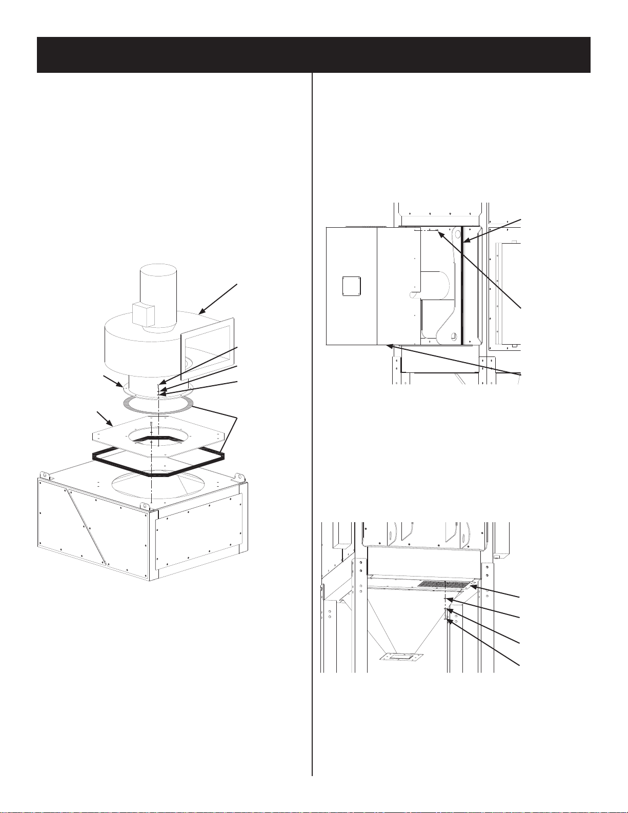
TOP MOUNTED BLOWER
1. Apply self-adheasive foam to the bottom side of the
blower flange (Figure 10).
2. Carefully lift the blower and position over the adapter
plate using a lift truck or crane.
3. Align and lower the blower to the top of the adapter
plate, ensuring the blower outlet is in the correct
discharge orientation for your installation.
4. Install all bolts through the blower flange into the
adapter plate and tighten until secured.
Note: In most installations the adapter plate will arrive
installed on the unit. In the event it needs relocated to
another module see figure 10.
REAR MOUNTED BLOWER MOTOR SHROUD
Note: Do not install motor shroud before completing the
electrical connection to the motor.
1. Place the motor shroud, as shown in Figure 11 over
the motor having located the slotted hole of the motor
shroud on the right hand side. This will allow the
wiring conduit to clear the motor shroud.
2. With the shroud in place mark the centers of the six (6)
holes in each vertical brace.
3. With the holes having been marked remove the motor
shroud and use a 7/32” diameter drill bit to drill
through the braces.
4. Apply the self-adheasive foam to the vertical braces as
shown in Figure 11.
5. Re-install the motor shroud around the motor and
attach using the twelve (12) self-tapping screws
provided.
6. The four bolts and small cover on the back of the motor
shroud may be removed to allow for the checking of
proper motor rotation.
REAR MOUNTED BLOWER SILENCER & REAR
MOUNTED HEPAAFTER FILTER
1. Remove the bolts from the exhaust grille (Figure 12A).
2. Align holes from the silencer flange with holes located
on the exhaust grille.
3. Attach the silencer with the hardware removed in step
one (Figure 12B)
8
FIGURE 10
Lock Washer
Flat Washer
Hex Bolt
Self-Adheasive
Foam
Self-tapping
Screw
Adapter Plate
Blower Flange
FIGURE 11
Self-Adheasive
Foam
Motor Shroud
FIGURE 12A
Exhaust Grille
Lock Washer
Flat Washer
Hex Bolt
Blower

FRP MICRO AIR®
CLEAN AIR SYSTEMS
MAGNEHELIC GAUGE
1. Mount the magnehelic gauge into the magnehelic
mounting bracket following the mounting instructions
contained in the magnehelic packaging.
2. Mount the two male barb fittings in the pressure ports
located on the side of the magnehelic gauge.
3. Mount the two pressure port plugs in the pressure ports
located on the back of the magnehelic gauge.
4. Mount the bracket using the four (4) self-taping screws
provided.
5. Using the 1/4” diameter clear tubing connect the
“LOW” or “-” pressure port on the gauge to the clean
air plenum and the “HIGH” or “+” pressure port to the
dirty air plenum (Figure 13).
PHOTOHELIC GAUGE
1. Mount the photohelic gauge into the photohelic
mounting bracket following the mounting instructions
contained in the photohelic packaging.
2. Mount the two male barb fittings in the pressure ports
located on the side of the photohelic gauge.
3. Remove cover from electrical box so that wiring
diagram on back of cover can be used.
4. Remove the two red wires that are connected to the
timer board pressure switch input (HI & COM) and
relay CR1, or the two red wires that are connected to
the timer board pressure switch input (HI & COM)
and the differential pressure switch (HI & LOW). See
specific unit wiring schematic for further clarification.
5. Wire the photohelic gauge as the electrical diagram
shows. Use the 3/4” conduit opening on the
photohelic, connecting to the pulse control electrical
box.
6. Replace the cover back onto the photohelic gauge and
mount the bracket using the four (4) self-taping screws
provided.
7. Using the 1/4” diameter clear tubing connect the
“LOW” or “-” pressure port on the gauge to the clean
air plenum and the “HIGH” or “+” pressure port to the
dirty air plenum (Figure 14).
8. The right set point dial of the gauge should be
positioned at the filter differential set point you want
the Roto-pulse system to be enabled. The left should
be positioned at the filter differential set point you wnat
the Roto-pulse sytem disabled.
9
FIGURE 12B
Exhaust Grille
Lock Washer
Flat Washer
Hex Bolt
Silencer
FIGURE 13
Clean Air
Plenum
Dirty Air
Plenum
FIGURE 14
Dirty Air
Plenum
Conduit to Pulse
Control Box
Clean Air
Plenum

MICRO AIR®FRP
CLEAN AIR SYSTEMS
COMPRESSED AIR INSTALLATION:
The compressed air inlet for the Roto-Pulse cleaning
system is at the top of the surge tank located on the side of
the unit (Figure 15). A minimum of a 3/4 inch diameter
line and clean, dry compressed air at a pressure of 80 psi
to 90 psi is required for proper operation of the Roto-pulse
cleaning system. For models FRP8-3 and FRP8-4 two 3/4
inch diameter lines from a minimum 1 inch diameter header
line are required. A unit specific combination regulator/
filter dryer is highly recommended for proper operation.
ELECTRICAL INSTALATION:
Caution: Installation can cause
exposure to live components. Disconnect
electrical power before proceeding with
installation. Proper lock out/tag out
procedures should be used.
PULSE CONTROLS ONLY ELECTRICAL BOX
1. Open the electrical box cover located on the side of the
unit. Make connections from your 120V supply power
to terminal L, N and G (Figure 16).
2. When supply power has been terminated, reconnect
the power. Momentarily turn the motor blower on and
adjust pressure switch via set screw until contact is
made. Use an ohm meter to measure continuity across
the pressure switch.
FULL CONTROL ELECTRICAL BOX
1. Determine the location for mounting the electrical box
(on the unit or remotely). If mounting is on the unit
mount near the pulse jumper box in order to minimize
electrical runs if feasible.
2. Mount the electrical box.
3. Open the electrical box cover located on the side of
the unit. Make connections from your 208V, 230V, or
460V supply power to power distribution terminal L1,
L2, and L3 (Figure 17). Wire size should be rated for
FLA of your application.
10
FIGURE 15
Compressed Air Inlet
3/4” Female NPT
!
Set Screw Power Connection
Pressure Switch
Timer Board
FIGURE 16
FIGURE 17
Timer Board
Overload Power Distribution
Terminal
Contactor
FRP MICRO AIR®
CLEAN AIR SYSTEMS
4. Wire from the Overload T1, T2, and T3 to the motor
electrical housing. Wire size should be the same as
step 3.
5. Wire from the timer board in the full control electrical
box and the pulse jumper box on the side of the unit.
Wire size is 14AWG minimum.
6. Reconnect the power. Momentarily turn the unit
on and off with the start/stop switches. Confirm
the rotation of the motor is in the proper direction.
Rotation can be viewed at the open end of the blower
motor.
7. If motor rotation is in the proper direction then AMP
draw information is located on the inside of the Full
Electrical Control Box cover. If motor current is higher
than rated for the motor supplied, do not continue
operation. Re-check your wiring and if problems
continue contact your Micro Air representative for
instructions.
UNIT OPERATION:
1. Turn the blower on. This action will cause the filter
unit to activate and start cleaning filters.
2. Once the unit is running, the Roto-Pulse cleaning
system will be operational. Operation is detected by
hearing a 0.07 second air pulse approximately every 5
seconds. If adjustment to timing of pulses is desired
refer to the section “Roto-Pulse Cleaning Timer
Adjustments”.
3. Check the After-Pulse cleaning cycle by turning off
the blower. The unit should continue to pulse every 5
seconds for a period of approximately 17 minutes. If
adjustment to the after-pulse time is desired refer to the
section “After-Pulse Cleaning Timer Adjustments”.
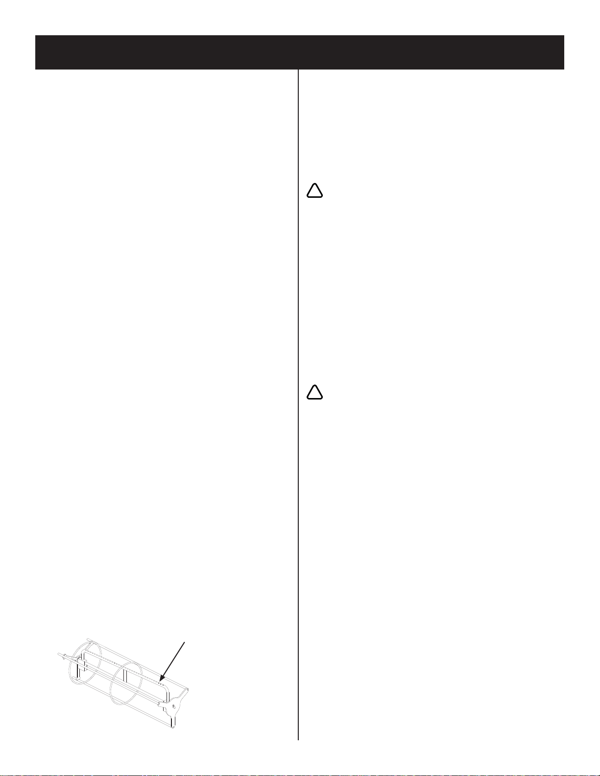
CARTRIDGE CLEANING OPERATION:
The Micro Air Dust Collector is designed with the
Roto-Pulse Cleaning System to clean the cartridge filters.
This system provides superior cleaning performance using
a rotating tube with pre-drilled holes. As the pulse valve
opens, the Roto-Pulse tube rotates while air exits the holes,
thus providing the cleaning of the cartridge (Figure 18).
1. For proper cleaning, the compressed air pressure should
be regulated at 80 psi to 90 psi.
2. During normal operation the Roto-Pulse cleaning
system is factory set to clean two (2) cartridge filters
for a period of 0.07 seconds every 5 seconds.
3. Once the unit is turned off the cleaning cycle will
continue for a period of 17 minutes. Do not service the
filters until cleaning is completed.
Caution: Allow 20 minutes of downtime
before opening filter access doors.
After-Pulse system is operational after unit
is turned off.
4. The Roto-Pulse cleaning operation dislodges particles
from the cartridges. Particles then fall down into the
dust tray or collection hopper.
5. After continued use of the unit, the dust collection
barrel or dust tray will need to be emptied. The
frequency of servicing will vary depending on the type
and quantitity of dust that is collected.
ROTO-PULSE CLEANING TIMER
ADJUSTMENTS:
Caution: Adjustment can cause
exposure to live components.
1. Turn the blower off.
2. Open the electrical box cover.
3. The timer control board is preset at the factory to clean
two (2) cartridge filters every 5 seconds. This time can
be adjusted from 1 second to 999 seconds. To adjust
this time press the select button on the timer board until
the “off time” LED is lit. Press the up/down buttons
until the desired value is displayed. Press select to set
the new value.
Note: Cleaning of the filters too often will decrease your
level of performance. A certain level of dust cake on
the filters will improve the capture efficiency of the
filters. You should try to maintain a mimimum of 1 in.
w.c. of pressure differential across the filters. If you
can not maintain this minimum level of differential
pressure across the filters the time between cleaning
pulses should be increased until this can be achieved.
4. The timer control board is preset at the factory to have
a cleaning pulse duration of 0.07 seconds. This can be
adjusted from 0.05 seconds to 600 seconds. To adjust
this time press the select button on the timer board until
the “on time” LED is lit. Press the up/down buttons
until the desired value is displayed. Press select to set
the new value.
11
FIGURE 18
Roto-Pulse Tube
!
!

MICRO AIR®FRP
CLEAN AIR SYSTEMS
Note: While this time can be adjusted it is recommended
that you leave the “ON TIME” at the factory setting.
If less cleaning is needed you should increase the time
between pulses as a means of reducing the amount
of cleaning. If more cleaning is needed you should
decrease the amount of time between pulses. Beware,
as the time between pulses is decreased for additional
cleaning, this will increase your compressed air
consumption and create an additional load on your
compressed air system.
5. Once adjustments have been made close the electrical
box cover.
6. Start the unit and observe the new pulse settings and
determine if additional adjustments are necessary. If
more adjusting is needed, repeat the previous steps.
AFTER-PULSE CLEANING TIMER
ADJUSTMENTS:
Caution: Adjustment can cause
exposure to live components.
1. Turn the blower off.
2. Open the electrical box cover.
3. The timer control board is preset at the factory to have
an After-Pulse cleaning duration of 999 seconds (17
minutes). This can be adjusted from 0 seconds to 999
seconds. To adjust this time press the select button on
the timer board until the “off time” LED is lit. Press
and hold the select button for 3 seconds. Press the up/
down buttons until the desired value is displayed. Press
select to set the new value. The after-pulse operation
can be disabled by setting the time value to zero (0)
seconds.
12
!
FRP MICRO AIR®
CLEAN AIR SYSTEMS
13
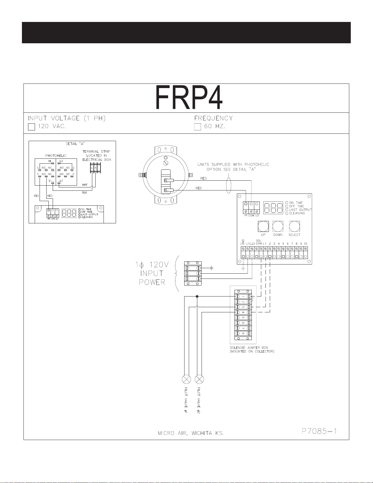
FRP4 PULSE CONTROL ONLY WIRING DIAGRAM
14
MICRO AIR®FRP
CLEAN AIR SYSTEMS
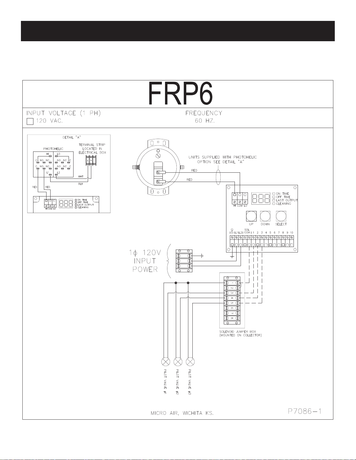
FRP6 PULSE CONTROL ONLY WIRING DIAGRAM
15
FRP MICRO AIR®
CLEAN AIR SYSTEMS
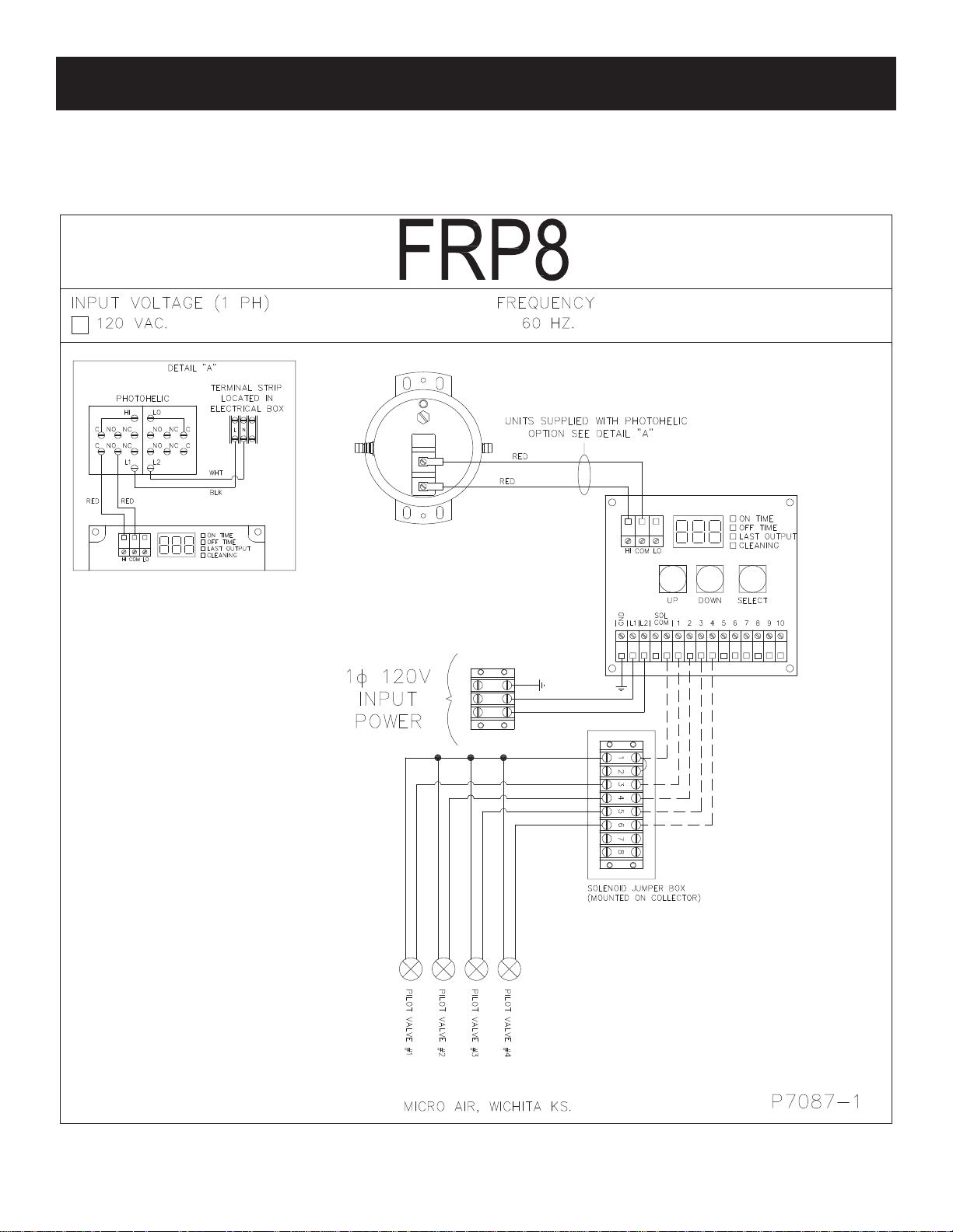
FRP8 PULSE CONTROL ONLY WIRING DIAGRAM

16
MICRO AIR®FRP
CLEAN AIR SYSTEMS
FRP6-2 PULSE CONTROL ONLY WIRING DIAGRAM

17
FRP MICRO AIR®
CLEAN AIR SYSTEMS
FRP6-3 PULSE CONTROL ONLY WIRING DIAGRAM
18
MICRO AIR®FRP
CLEAN AIR SYSTEMS
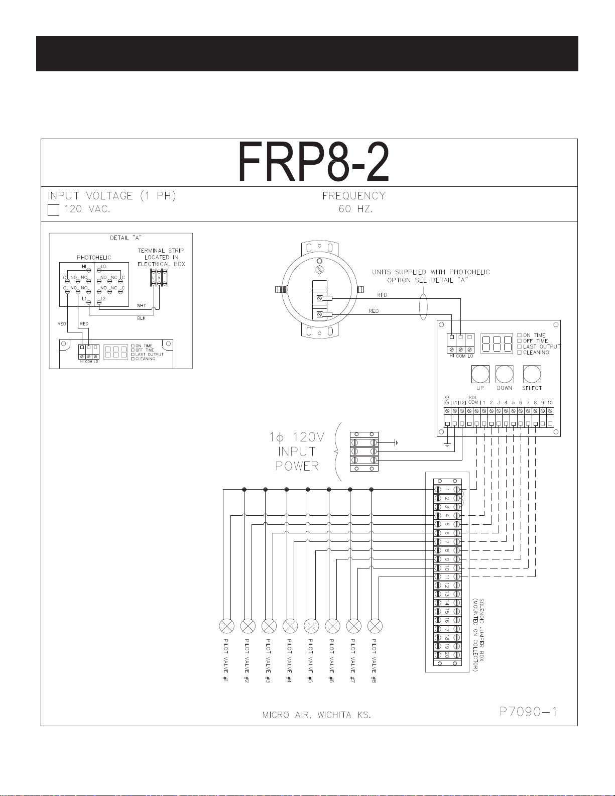
FRP8-2 PULSE CONTROL ONLY WIRING DIAGRAM

19
FRP MICRO AIR®
CLEAN AIR SYSTEMS
FRP8-3 PULSE CONTROL ONLY WIRING DIAGRAM

20
MICRO AIR®FRP
CLEAN AIR SYSTEMS
FRP8-4 PULSE CONTROL ONLY WIRING DIAGRAM
This manual suits for next models
8
Table of contents
Other MICRO-AIR Dust Collector manuals


Popular Dust Collector manuals by other brands


 owner's manual")


Chiko
Chiko CBA-500AT3-HI instruction manual

King Industrial
King Industrial KC-4043KWRC Service manual

Jet
Jet IAFS-1700 Operating instructions and parts manual

Powermatic
Powermatic PM1900 Instructions and parts manual

Blastrac
Blastrac 655DC operating instructions

Elektra Beckum
Elektra Beckum SPA 2000 Betriebsanleitung


