MICRO-AIR Twister RP1 User manual

TWISTER
Micro Air®Installation and Operation Manual
IMPORTANT:
This manual contains speci!c cautionary statements relative to worker safety. Read this manual thoroughly and
follow as directed. It is impossible to list all the hazards of dust control equipment. All persons involved with the
equipment or systems should be instructed how to operate in a safe manner.
RP1

CAUTIONS:
Avoid mixing combustible materials, such as buf•ng
lint, paper, and wood with dust generated from
grinding ferrous metals due to the potential •re hazard
caused by sparks in the unit.
Under no conditions should cigarettes or any other
burning object be put into the unit.
All users of MicroAir dust collection equipment
should comply with all National and Local Fire Codes
and/or other appropriate codes when determining the
location and operation of dust control equipment.
This unit is not suited for applications where explosion
potential is present. Consult the Factory to determine
if there is a risk.
SPECIFICATIONS:
INPUT VOLTAGE:
120V 60Hz 1 Phase
MOTOR/CURRENT:
1.5HP 1PHASE 3450RPM TEFC 120V: 18Amps
OVERALL DIMENSIONS:
Base Unit: 76” H x 25” W x 20” D
FILTER AREA:
80/20 Media: 174 Sq. Feet
Poly Media: 150 Sq. Feet
AIR REQUIREMENTS:
• Minimum air line is 3/4”
• Air Pressure regulated 80 – 90 psi.
• Clean, dry, compressed air at the correct pressure
is required for the cleaning system to operate
correctly. It is recommended that a pressure
regulator and coalescing •lter be installed
between the compressed air source and the inlet
to the table.
INSTALLATION:
INSPECTION:
The MicroAir Twister (RP1) is shipped on one skid.
This skid should be inspected for any visible damage
that may have occurred during shipment. Note any
damage on the packing slip.
EQUIPMENT/TOOLS REQUIRED:
• Standard wrenches.
• Screwdriver
• Forklift
• Pipe Wrench
ASSEMBLY OF UNIT:
Determine the location where the unit is to be
installed. Be sure to allow suf•cient room around the
unit to service the •lters, and allow for exhaust air.
1. Uncrate the unit. Use caution not to damage the
paint while dismantling the crate.
2. Remove any options ordered from the skid.
3. Assemble the optional wall bracket onto the
unit.
4. Carefully mount the unit into its location.
COMPRESSED AIR INSTALLATION
The compressed air inlet for the Roto-Pulse cleaning
system is on the side of the unit. A 3/4” air line is
required (at a minimum) with 80 – 90 psi clean dry
air, for proper operation of the Roto-Pulse®System.
1. Locate the compressed air connection.
2. Connect your standard air •tting to the provided
3/4” NPT thread.
3. Connect your air line to the •tting.
1

ELECTRICAL INSTALLATION:
ALL ELECTRICAL WORK MUST BE DONE BY
A QUALIFIED ELECTRICIAN ACCORDING
TO LOCAL CODES
INSTALLATION CAN CAUSE EXPOSURE TO
LIVE COMPONENTS. DISCONNECT ELEC-
TRICAL POWER BEFORE PROCEEDING
WITH INSTALLAITON. PROPER LOCK OUT/
TAG OUT PROCEDURES SHOULD BE USED.
If the unit is ordered with 120V electrical wiring there
is no additional wiring required. Simply plug the unit
into any 110/120V electrical plug rated for 15A.
UNIT OPERATION:
1. To start the unit, turn the switch located on the
front of the unit to the on position. To stop the
unit, turn the switch to the off position.
CARTRIDGE CLEANING OPERATION:
The Micro-Air®Twister is designed with the Roto-
Pulse® Cleaning System to clean the cartridge !lters.
This system provides superior cleaning performance
using a rotating tube with pre-drilled holes. As the
diaphragm valve opens, the Roto-Pulse®tube rotates
while air exits the holes, thus providing the cleaning of
the cartridge.
• For proper cleaning, the compressed air pressure
should be regulated at 80 - 90 psi maximum.
• During normal operation the Roto-Pulse®
cleaning system is activated by depressing the
pulse button located on the electrical box.
• The Roto-Pulse®cleaning operation dislodges
particles from the cartridges. Particles then fall
down into the collector.
NOTE: When servicing the collection system, be sure
to turn the unit off.
PULSE TIMING:
The Twister is provided with a manual pulse option
as the standard for all units. The !lters can be pulse
cleaned by depressing the pulse button (located on
the front of the electrical box) and holding it down
for approximately 2 seconds. Since the unit does not
have “Auto-Pulse” the !lters should be pulse cleaned
regularly throughout the day. In addition they should
be pulsed several times after the blower has been shut
off.
NOTE: Cleaning of the filters too often will decrease
your level of performance. A certain level of dust
cake on the filters will improve the efficiency of the
filter cartridges. You should try to maintain a mini-
mum of 1 in w.c. of pressure differential across the
filters. If you can not maintain this minimum level
of differential across the filters the time between
cleaning pulses should be increased until this can be
achieved.
MAGNAHELIC INSTALLATION:
1. Turn off dust collector and disconnect power to
the unit.
2. Mount the Magnehelic Gauge into the
Magnehelic Mounting Bracket and place the (2)
male barb !ttings in the pressure ports locatedon
the side of the Magnehelic Gauge.
3. Also use the two pressure port plugs supplied
with the Magnehelic Gauge on the two ports
located on the backside of the gauge.
4. Mount the bracket. Do not mount the bracket on
the unit. Mounting screws may damage internal
components.
5. Using 1/4” clear tubing (Additional length can be
purchased) connect the “LOW” pressure port on
the gauge to the clean air plenum and “HIGH”
pressure port to the dirty air plenum.
6. Reconnect the power to the unit and start the dust
collector.
2
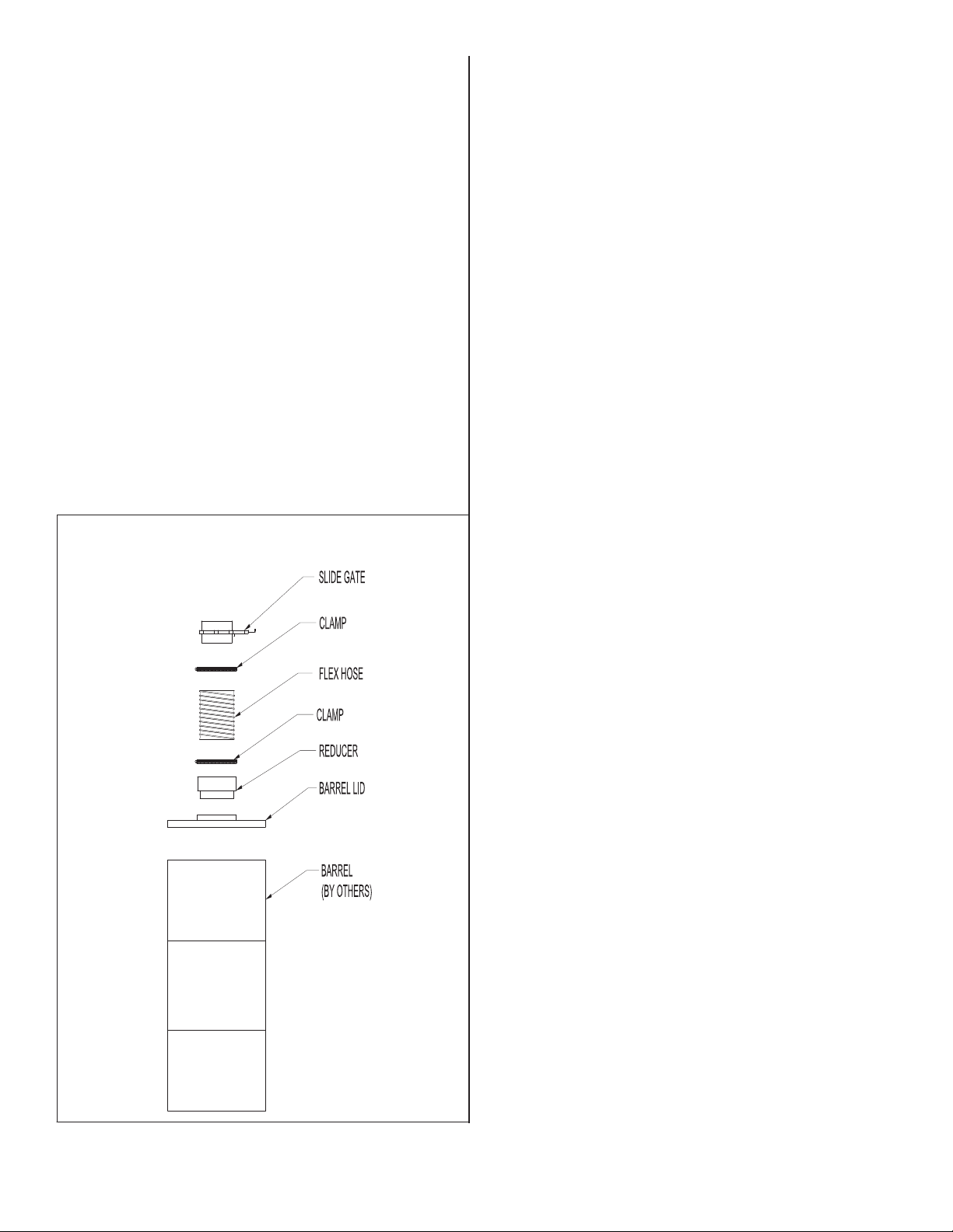
BARREL LID INSTALLATION:
1. Remove parts from box and inspect for any
possible damage incurred during shipping.
2. Using the 10” hose clamp attach the 8” flex hose
to the collar on the slide gate.
3. With the remaining 10” hose clamp attach the
barrel lid flex hose to the collar on the top of the
8” to 10” reducer.
4. Attach the 10” side of the reducer to the barrel
lid.
5. With barrel lid installed a 55 gallon barrel (not
provided) can be placed under the barrel lid for
material collection.
FILTER CHANGE:
1. Turn unit off. Manually pulse the unit several
times to remove excess material from the filter.
2. Disconnect power to the unit.
3. Open the slide gate to empty any remaining
material from the hopper.
4. Remove the barrel, barrel lid kit, and hopper by
loosening the lowest joint band. The drop out
plate will come off with the hopper.
5. Remove the 4-Prong knob and seal washer from
below the filter. Save the knob.
6. Slide the filter down out of the unit.
7. Reverse steps 4-6 to install new filter.
See Parts List Diagram for additional assistance.
3

Parts List Diagram
Item # Part # Description Item # Part # Description Item # Part # Description
1 36720-10 Roto-Pulse Assembly 20 P1050 Edge Protector 35 P2704 3/8” Washer
2 38151-01 Body Weldment 21 P119 5/16-20 Bolt 36 P2766 Pulse Push Button
3 38154-01 Clean Air Plenum 22 P124 3/8 - 16 Bolt 37 P3403 5/8” ID Hose
4 38155-01 Roto-Pulse Seal Plate 23 P1363 Cord w/Plug 38 P3411 1” Hose Clamp
5 38155-02 Blower Seal Plate 24 P141 3/8” Nut 39 P3158 8” Slide Gate
6 38155-03 Motor/Fan Plate 25 P142 3/8” Lock Washer 40 P345 14 Ga Cord
7 38155-04 Drop-Out Plate 26 P164 1/4-20 Bolt 41 P3508 5/16” Rivnut
8 38155-05 Exhaust Grill 27 P1954 Cord Strain Relief 42 P3559 Rubber Washer
9 38158-01 Hopper 28 P2059 #8 Screw 43 P3585 Hose Barb
10 38160-01 Silencer Assembly 29 P2075 Diaphram Valve 44 P3649 Knob
11 38162-01 Joint Band 30 P2301 1 1/2HP Motor 45 P3734 1/4” OD Air Hose
12 38165-01 Electrical Box Weldment 31 P2302 Blower Assembly 46 P3735 90° Presto Lock
13 38168-01 Electrical Box Cover 32 P233 5/16” Washer 47 P3924 Straight Presto Lock
33 P242 1/4” Lock Washer 48 P7401RM 80/20 Cartridge Filter
34 P249 5/16” Lock Washer 48 P7410RM Poly Cartridge Filter
4

Notes:
Installation Date: Location:
Machine Number: Installer:
Air Pressure: Air Line Size:
FilterType: 80/20 Cellulose Media (Red) OR Polyester Media (White)
Distributor Company: Contact Name:
Phone Number: ( ) -
Other Notes:
Micro Air Inc Form. No. L2466 09/18
5
Table of contents
Other MICRO-AIR Dust Collector manuals


Popular Dust Collector manuals by other brands


ROMANOFF
ROMANOFF 1000 CFM product manual

Oneida Air Systems
Oneida Air Systems XXVM001500 owner's manual

ILMEG
ILMEG X-150 Installation and operating instructions

Enke
Enke I.VAC User and maintenance handbook

ISTblast
ISTblast DCM-100 instruction manual

Oneida Air Systems
Oneida Air Systems XXK050100 owner's manual

Donaldson Torit
Donaldson Torit TBV-2 Installation and operation manual

Woodtec
Woodtec XW117 instruction manual

Bucktool
Bucktool DC30A instruction manual

Jet
Jet DC-1200-M operating instructions

Donaldson Torit
Donaldson Torit Unimaster UMA 40 Installation and operation manual

Texas Equipment
Texas Equipment COLLECTOR BOX Assembly instruction