M.D. Micro Detectors
Strada S. Caterina, 235
41122 Modena Italy
Tel. +39 059 420411
Fax +39 059 2539 3
www.microdetectors.com
RETROREFLECTIVE AREA SENSOR
LANGUAGE
Installation and Operation Manual ENGLISH
M.D. Micro Detectors CATXXXXXX 11/15
5.0 START-UP INSTRUCTIONS
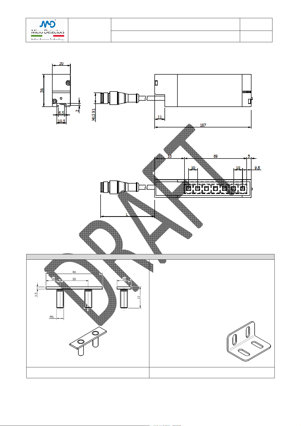
5.1 Mechanical mounting of CR models
It is extremely important to fix the sensors and the reflectors to a rigid structure, not subject to deformation or to strong vibrations.
Choose the position of the sensor so as not to expose it to strong sources of natural or artificial light and to light interference ith
other sensors in the visible emission.
Keep in mind that the devices are not suitable for outdoor installation, IP67 despite being declared, it is not guaranteed that the long
exposure to the eather does not cause ater penetration and performance degradation.
Choose the most suitable reflector to the required detection capabilities and sensing range.
Mount the sensor ith the optical axes as much as possible perpendicular to the reflector surface. The mutual distance depends on the
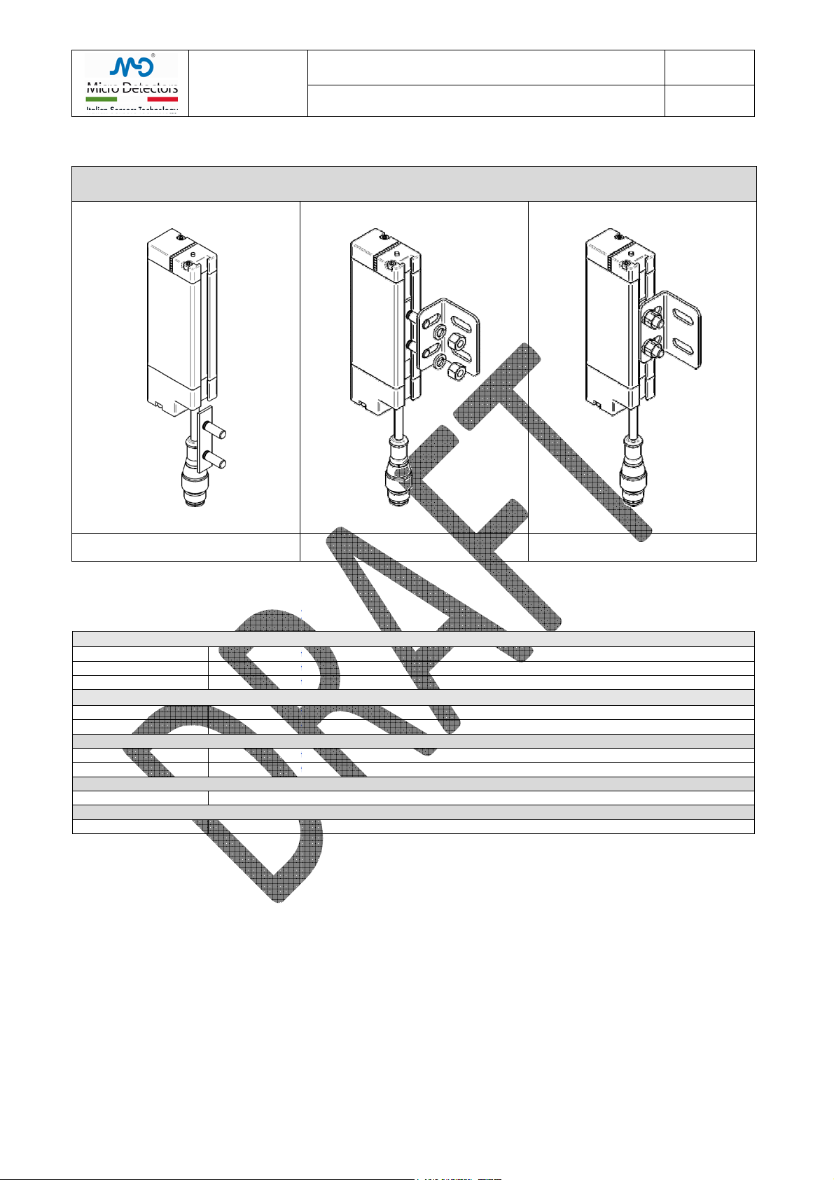
type of reflector and must be included in the field of specification. To secure the sensors to a support, use the corresponding inserts to
be applied in the rear groove and the brackets in the normal provisioning.
If the application is subject to vibrations, hich any ay do not prevent the optical alignment, use damping supports.
Though used polarized light, the light beams can in part be deflected by reflective surfaces parallel and near to the beams, this can
lead to a missed detections of the interruption of direct path of the of the optical beam, or incorrect calibration values that may
generate unstable operation, so all reflective surfaces and reflective objects should maintain a minimum distance from the direct path
of the rays. This distance depend on the aperture angle of optics.
Keep in mind that even if a surface is black, if it is shiny, it can be highly reflective.
If you can’t eliminate or reduce the effect of a reflective surface, it is important that this effect remains stable or that
the system behaves in an acceptable and predictable manner.
Temporarily block the sensor and reflector so that they are aligned and parallel to each other.
5.1 Electrical installation
Use PELV po er supplies, in compliance ith Chap.6.4. of EN 60204-1.
If using a non-stabilized po er supply, the transformer must have double insulation and adequate po er, the secondary inding must
not exceed 18Vac. Use a bridge rectifier, a filtering capacitor ith a minimum value of 1000μF.
Connect the supply cables directly to the source and not do nstream of other po er or highly inductive devices.
Run the cables of the light curtains in dedicated race ays or here only signals run; do not use race ays already carrying po er
cables.
Comply ith the specification of the maximum length of the connection cables. Make sure that the part or parts of the metal structure
on hich the sensors are installed are effectively connected to the same earth ground.
Before inserting the connector, check that the mains voltage and the supply voltage are ithin the required limits, apply the connector
and check again that the supply voltage has a correct nominal value and remains ithin the limits defined in all orking conditions.
Check the limits in the t o extreme conditions of minimum and maximum absorption of all devices connected to the same po er
supply, especially if this is not a stabilized po er supply.
Danger!
In order to carry out the follo ing operations, a voltage supply to the sensor is needed. Before starting this phase,
make sure that the outputs’ s itch cannot lead to any danger.
Make the minimum electrical connections for proper operation, connect the po er cables, connected to the necessary
inputs devices; suitably connected the NC / NO input if it is available, this status is only acquired at po er on.
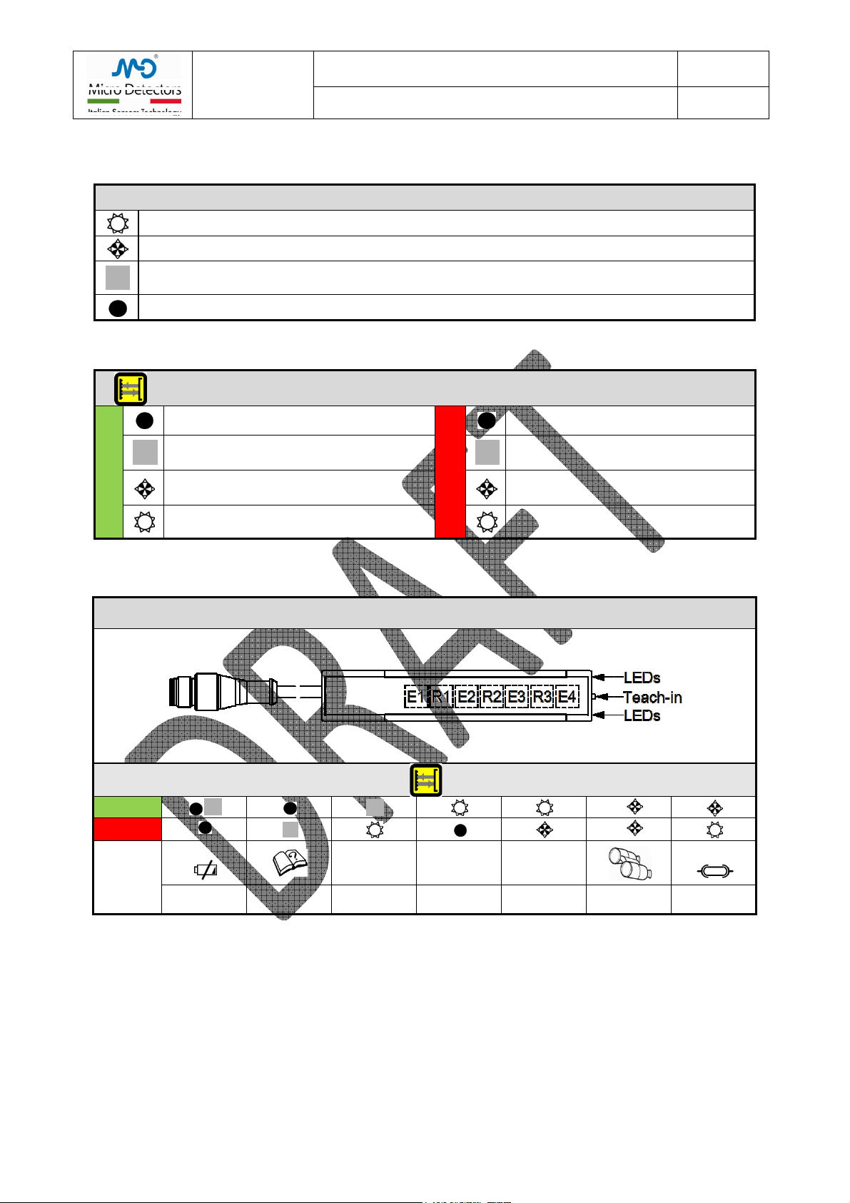
5.2 Alignment of CR0 models
Applied the supply voltage, the Green LED must be s itched on, if it is off or flashes the supply voltage is not sufficient.
Verify that the emission optics are active and therefore emit a red light, if necessary make a teach-in (even ithout visibility of the
reflector) ith the purpose to activate the alignment function. If possible, observe the reflector from a point near the optical axis and
corrects the alignment so that the light stain completely illuminate the reflector, simultaneously or alternatively use the alignment
function of the Red and Green LED (reduce the red light to a minimum).
Fix the sensor and run no a Teach_F and check the status of the LEDs, if the Red LED is off and the Green on, the alignment as
acceptable and the Teach as successful. If both LEDs are still blinking it means that the alignment is incorrect, so try to get a better
alignment then run a second Teach G or F. After successfully aligned, permanently block the sensor and verify that the sensor detects
properly as expected. If possible, urging the structure, verify that the vibrations do not cause unstable operation.
If the LEDs sho no recognizable behaviors check the error codes in Chapter 5.5
A correct optical alignment ith a good signal margin prevents unstable functioning of the light curtains, reduces
optical interferences and reflection by shiny surfaces and guarantees better stability in general.
If the range is short, the graininess of the reflector can cause instability, check the behaviour of the system by shifting
the reflector, as an alternative use of reflective paper composed of micro prisms.
the cables and to control the correct functioning of the application.