Micro Detectors CR0 Series User manual
!
M.D. Micro Detectors
Strada S. Caterina, 235
41122 Modena Italy
Tel. +39 059 420411
Fax +39 059 253973
www.microdetectors.com
CR0 SERIES
RETROREFLECTIVE AREA SENSOR
LANGUAGE
Installation and Operation Manual
ENGLISH
M.D. Micro Detectors
CAT8ECR1780101
1/16
!
!

!
M.D. Micro Detectors
Strada S. Caterina, 235
41122 Modena Italy
Tel. +39 059 420411
Fax +39 059 253973
www.microdetectors.com
CR0 SERIES
RETROREFLECTIVE AREA SENSOR
LANGUAGE
Installation and Operation Manual
ENGLISH
M.D. Micro Detectors
CAT8ECR1780101
2/16
!
!
SUMMARY
1.0!ABOUT)THIS)DOCUMENT)...............................................................................................................)3!
1.1!Function!of!this!manual!.....................................................................................................................!3!
1.1!Explanation!of!symbols!.....................................................................................................................!3!
2.0!SAFETY)AND)PROPER)USE)..............................................................................................................)3!
3.0!PRODUCT)DESCRIPTION).................................................................................................................)4!
3.1!Short!description!...............................................................................................................................!4!
3.2!Available!models!...............................................................................................................................!4!
3.3!Functions!description!........................................................................................................................!5!
3.3.1!Behavior!at!power-on!....................................................................................................................!5!
3.3.2!Teach!in!.........................................................................................................................................!6!
3.3.3!Beams!exclusion!menu!(blanking)!and!restore!factory!setting.!....................................................!7!
3.1!Electrical!drawing!..............................................................................................................................!8!
4.0!TECHNICAL)SPECIFICATIONS).........................................................................................................)10!
5.0!START-UP)INSTRUCTIONS).............................................................................................................)12!
5.1!Mechanical!mounting!of!CR!models!................................................................................................!12!
5.1!Electrical!installation!.......................................................................................................................!12!
5.2!Alignment!of!CR0!models!................................................................................................................!12!
5.5!Display!indications!and!diagnostics.!................................................................................................!13!
6.0!MECHANICAL)DIMENSIONS)OF)LIGHT)CURTAINS)AND)STANDARD)ACCESSORIES)..........................)14!
6.1!Mechanical!dimensions!!of!CR0*/10-010V!!reflex!curtains!.............................................................!14!
6.2!Standard!Mounting!accessories!......................................................................................................!14!
7.0!INSTALLATION).............................................................................................................................)15!
8.0!LIST)OF)AVAILABLE)ACCESSORIES).................................................................................................)15!
9.0!PACKAGE)CONTENT).....................................................................................................................)15!
10.0!CONTROL)OF)THE)INSTALLED)RETROREFLECTIVE)AREA)SENSOR)....................................................)16!
10.1!Purpose!of!controls.!........................................................................................................................!16!
10.2!Preliminary!controls!before!start-up!...............................................................................................!16!
10.3!Controls!device!efficiency!...............................................................................................................!16!
!
M.D. Micro Detectors
Strada S. Caterina, 235
41122 Modena Italy
Tel. +39 059 420411
Fax +39 059 253973
www.microdetectors.com
CR0 SERIES
RETROREFLECTIVE AREA SENSOR
LANGUAGE
Installation and Operation Manual
ENGLISH
M.D. Micro Detectors
CAT8ECR1780101
3/16
!
!
1.0 ABOUT THIS DOCUMENT
Please read careful this document before installation, start-up, use and maintenance of CR0 light curtains. This manual contains detailed
instructions that must be carefully followed.
THIS MANUAL IS NOT IN THE ORIGINAL LANGUAGE
1.1 Function of this manual
This manual provides the user with the necessary instructions for safe and proper installation, electrical connection, start-up, use and
maintenance of CR0 retro-reflective area sensors.
1.1 Explanation of symbols
!
Warning
A warning sign indicates the presence of potential hazards.
It indicates procedures and behaviours which can be useful to prevent accidents.
Read and follow these instructions carefully.
!
Indication
It refers to indications that can help to achieve better performances.
!
Symbol
The symbol identifies optical devices that have the reflex function.
2.0 SAFETY AND PROPER USE
!
Warning
This it is NOT a protective device. Therefore, it should not be used to guarantee personnel safety.
!
Warning
CR0 works in DC and with a low voltage (the maximum value is 30VDC); the proper operation is guarantee only in
the range indicated in the technical data.
With voltages below 16VDC all outputs remain in the OFF state, with voltages in excess of 30VDC permanently, the
device may be damaged.
When the device is switched ON, outputs are inactive for a certain amount of time known as power on delay (see
the following documentation).
!
Warning
Some optics emit visible light that do not have dangerous levels; the device is classified RG0 (Exempt Group)
according to IEC 62471 standard: 2006-07.
!
!
Warning!
Please make sure that light curtains are used in proper environmental conditions.
Manual or automatic calibration must always be carried out aiming at the best possible alignment. More than one
calibration and alignment adjustment may be necessary to guarantee the best alignment.
Check any reflective surface next to the light beams which may influence them.
Check any transparent or similar panels which may change the beam angle of the area sensor.
Prevent the area sensor 's optical window from getting scratched or tarnished.
Do not expose the area sensor to strong natural or artificial light sources, including stroboscopic light.
Do not expose the area sensor directly to optical beams projected by other optical devices.
Ensure that the ambient temperature does not exceed the stated limits.
Keep in mind that smoke, vapour, liquids and powders may alter transparency of air or dirty the optical window.
Dispose of unusable or irreparable devices always in accordance with national regulations regarding waste disposal.
!
!
M.D. Micro Detectors
Strada S. Caterina, 235
41122 Modena Italy
Tel. +39 059 420411
Fax +39 059 253973
www.microdetectors.com
CR0 SERIES
RETROREFLECTIVE AREA SENSOR
LANGUAGE
Installation and Operation Manual
ENGLISH
M.D. Micro Detectors
CAT8ECR1780101
4/16
!
!
3.0 PRODUCT DESCRIPTION
3.1 Short description
CR0 light curtains are photoelectric devices built according to the IEC 60497-5-2 norms and they must not be considered as safety
devices. Therefore they must not be used to guarantee operators’ safety nor to protect users on dangerous machines. They must
rather be used to detect objects reducing or obscuring the intensity of light beams that returns from the reflector.
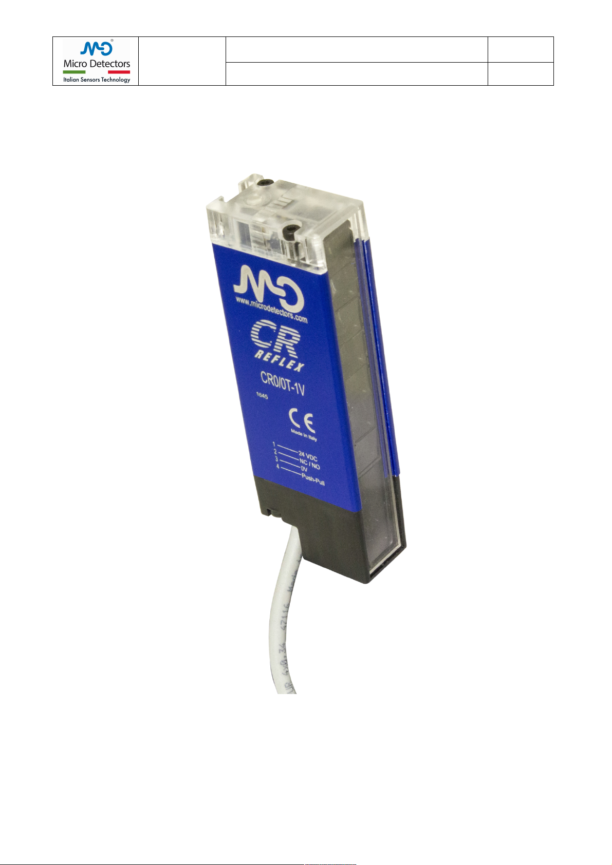
The housing is in aluminium painted in blue RAL5002, size 20x36mm, (20 mm refers to the front side). A groove on the back allows
connection with T-shaped components. The top side is in and the bottom side is in black PBT, the optical window is in PMMA.
Protection degree is IP67.
In all models of the series, CR0 have two LEDs indicators: Red and Green in combination, indicate the states of the sensor
(alignment, state optics and fault indication), they are arranged at the top of the curtain, the light is intense and diffused in all
directions, this ensures a great visibility in all conditions.
All models in the CR0 have an optic composed of a continuous array of 9x9mm lenses with a step of 10mm, CR0 have seven
lenses. The optical window has a height of 69mm; the total height of the curtain is 107mm.
Emitter and Receiver are alternate with the following sequence is: E1, R1, E2, R2, E3, R3, E4 with reference the cable side. This
allows to realize a continuous succession of six pairs of reflex elements; the emitted light is polarized and has a wave length of
617nm.
The working distance is 0.2...4.5m with reflector RL106Gand lower with smaller reflectors, the best detection capability is 6mm.
All models of CR0 series have a teach button (inductive teach could also be available) in the top of the curtain dedicated to the
activation of menu functions: two levels of Teach-in and Blanking.
The Teach_S(standard teach) select an excess gain equal to 2 times the threshold, the Teach_F (fine teach) select an excess gain
equal to 1.2 times the threshold; the latter should be used only if the system and the environment in which the product is used are
clean and with an high mechanical stability.
The sensor does not use automatic systems of signal tracking, but its repeatability is based on a sophisticated control of thermal drift.
The Blanking of the beams, allows gradually eliminate pairs of beams; the active couples (E+R) may range from a maximum of six to
a minimum of one.
This sensors has a standard output with M12 male flying connector (240 mm pigtail).
The CR0 models have four interface circuits which can be combined in different ways depending on the model and the number of
output cables:
a) Supply 15...30V
b) IO_Link output (C/Q), PNP/NPN/PUSH- PULL
c) Auxiliary output (Q): PNP/NPN/PUSH- PULL
d) Auxiliary input, output mode selection LIGHT/DARK (NC/NO) or more.
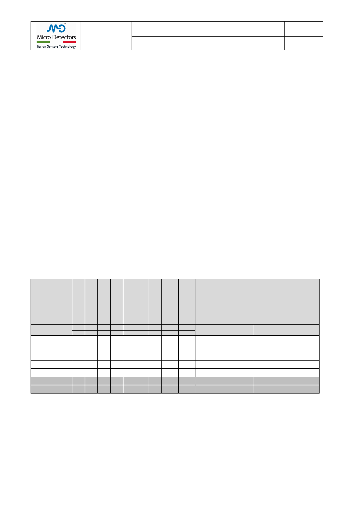
3.2 Available models
MODEL
OPTICAL PITCH
OPTICAL HEIGHT
BODY HEIGTH
OPTICS
SENSING
RANGE
RESPONSE
TIME
CONNECTOR
POLES
Interface
CODE ARTICLE
P
h
H
Sn
Tr
INPUTS
OUTPUTS
mm
mm
mm
N°
m
ms
No
CR0/0I-1V
10
69
109
7
0.2... 4.5
1.5
M12
4
None
b) IO_Link
CR0/0B-1V
10
69
109
7
0.2... 4.5
1.5
M12
5
d) NC/NO
b) PNP; c) NPN
CR0/0T-1V
10
69
109
7
0.2... 4.5
1.5
M12
4
d) NC/NO
b) Push-Pull
CR0/BP-1V
10
69
109
7
0.2... 4.5
1.5
M12
4
None
b) PNP-NO; c) PNP-NC
CR0/BN-1V
10
69
109
7
0.2... 4.5
1.5
M12
4
None
b) NPN-NO; c) NPN-NC
CR0/0P-1V
10
69
109
7
0.2... 4.5
1.5
M12
4
d) NC/NO
c) PNP
CR0/0N-1V
10
69
109
7
0.2... 4.5
1.5
M12
4
d) NC/NO
c) NPN
Tab.:1

!
M.D. Micro Detectors
Strada S. Caterina, 235
41122 Modena Italy
Tel. +39 059 420411
Fax +39 059 253973
www.microdetectors.com
CR0 SERIES
RETROREFLECTIVE AREA SENSOR
LANGUAGE
Installation and Operation Manual
ENGLISH
M.D. Micro Detectors
CAT8ECR1780101
5/16
!
!
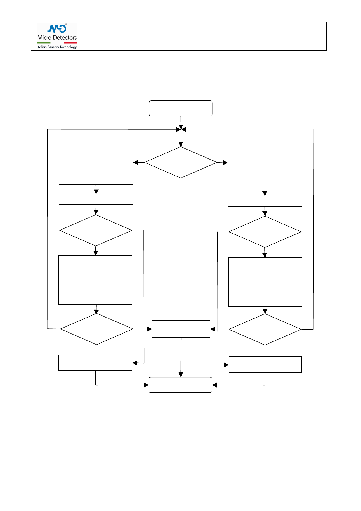
3.3 Functions description
3.3.1 Behavior at power-on
!
!
Power ON
All LEDs OFF!
Voltage <5V
5V<Votage <15V
!
Memory error
!
Green LED flashing
Red LED flashing
Flashing
!
See:
Restore factory setting
and
optic exclusion menu
Y
N
Y
Y
N
N
Normal operation
State
Green LED ON;
Red LED OFF.
Outputs state
as programmed.
Green LED ON; the Red LED
lights, with intensity inversely
proportional to the signal.
Outputs state as programmed.
Light
Dark
The Red LED lights;
Green LED flashing!
Non-recoverable
optical failure
Non-recoverable
optical failure
N
Y
!
M.D. Micro Detectors
Strada S. Caterina, 235
41122 Modena Italy
Tel. +39 059 420411
Fax +39 059 253973
www.microdetectors.com
CR0 SERIES
RETROREFLECTIVE AREA SENSOR
LANGUAGE
Installation and Operation Manual
ENGLISH
M.D. Micro Detectors
CAT8ECR1780101
6/16
!
!
3.3.2Teach in
!
!
Normal operation
Teach_in
Press the Teach button;
the Red LED lights;
the Green LED goes out;
Release the button
within 3s (before the Red
LED goes out and
the Green LED lights up).
The sensor starts a Teach_S
The alignment is right
G
F
Y
N
Press the Teach button;
The Red LED lights;
The Green LED goes out;
Release the button
3s elapsed (after the Red
LED turns OFF and
the Green LED lights up).
The Green LED flashes
proportional to the signal;
The Red LED flashes in
inverse proportion to the
alignment goodness.
Search for the best
alignment.
Fix the sensor
The sensor starts a Teach_F
The alignment is right
N
The Green LED flashes
proportional to the signal;
The Red LED flashes in
inverse proportion to the
alignment goodness.
Search for the best
alignment.
Fix the sensor
Y
Normal operation
Excess gain= 1.5
for current range
Excess gain= 1.2
for current range
Did you spend 2
minute?!
Did you spend 2
minute?
The previous set up is
taken!
Y
Y
N
N

!
M.D. Micro Detectors
Strada S. Caterina, 235
41122 Modena Italy
Tel. +39 059 420411
Fax +39 059 253973
www.microdetectors.com
CR0 SERIES
RETROREFLECTIVE AREA SENSOR
LANGUAGE
Installation and Operation Manual
ENGLISH
M.D. Micro Detectors
CAT8ECR1780101
7/16
!
!
3.3.3 Beams exclusion menu (blanking) and restore factory setting.
!
!
!
!
!
!
!
Power OFF
The Red LED lights;
Release Teach-in button.
The Red LED goes out.
Keep the Teach-in
button pressed
Power ON
Press the Teach button;
the Green LED lights;
Release the button
3s elapsed (after the Green
LED turns OFF and
the Red LED lights up).
Maximum ExG selected;
(Teach-in is recommended)
Beams exclusion menu:
All Red emitter (4) lights;
Emitters that contribute to a
single beam blink (E1, E4).
Emitters that contribute to a
couple of beams are steady.
Save
configuration ?
Y
N
N
Normal operation
Press the Teach button;
the Green LED lights;
Release the button
within 3s (before the Green
LED goes out and
the Red LED lights up).
A further beam has been
excluded
Is it the last beam?
Y
Restore factory
setting
With all optics
active
Normal operation
Press and leave the Teach-in button
pressed;
the Red LED lights up,
wait 3s for the
Green LED lights, Red LED goes out
wait 3s for the
Red LED lights, Green LED goes out
Release the Teach-in.
Red LED goes out
!
M.D. Micro Detectors
Strada S. Caterina, 235
41122 Modena Italy
Tel. +39 059 420411
Fax +39 059 253973
www.microdetectors.com
CR0 SERIES
RETROREFLECTIVE AREA SENSOR
LANGUAGE
Installation and Operation Manual
ENGLISH
M.D. Micro Detectors
CAT8ECR1780101
8/16
!
!
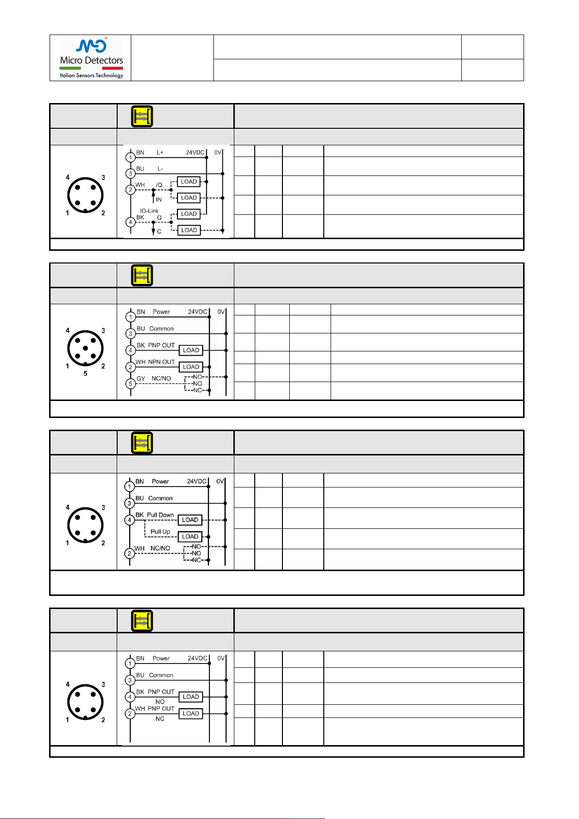
3.1 Electrical drawing
SERIE CR0
REFLEX
CURTAIN
CR0/0I MODEL
IO-Link interface
M12, 4 poles
Male connector
Wiring
Connector
Pin
Color
Signal
Description
1
BN
L+
Power supply input from 16 to 30V
2
WH
In/Q
Multifunction I / O
3
BU
L-
Supply voltage reference
4
BK
C/Q
IO-Link interface
NOTE:
Pin 2 is a multifuncion programmable I/O
Tab.:2
SERIE CR0
REFLEX
CURTAIN
CR0/0B MODEL
PNP and NPN outputs, NC/NO selectable
M12, 5 poles
Male connector
Wiring
Connector
Pin
Color
Signal
Description
1
BN
24VDC
Power supply input from 16 to 30V.
2
WH
NPN Out
Apply a load connected at the positive, maximum
current 100mA
3
BU
0V
Supply voltage reference
4
BK
PNP Out
Apply a load connected to the common, maximum
current 100mA.
5
GY or
YE/GR
NC/NO
Input for outputs logic selection.
NOTE:
The NC/NO input is read only when the sensor is switched ON. If it is left open or permanently wired to the common, it selects the output as
DARK ON. If it is connected to the positive, it selects the output as LIGHT ON. Enabling the button it is possible to execute the teach.
Tab.:3
SERIE CR0
REFLEX
CURTAIN
CR0/0T MODEL
Push Pull output, NC/NO selectable
M12, 4 poles
Male connector
Wiring
Connector
Pin
Color
Signal
Description
1
BN
24VDC
Power supply input from 16 to 30V.
2
WH
NC/NO
Input for outputs logic selection.
3
BU
0V
Supply voltage reference.
4
BK
Push Pull
Out
Apply a Pull up or a Pull down load
NOTE:
The NC/NO input is read only when the sensor is switched ON. If it is left open or permanently wired to the common the Push driver is Dark
switching and the Pull driver is Light switching. If it is connected to the positive the Push driver is Light switching and the Pull driver is Dark
switching.
Tab.:4
SERIE CR0
REFLEX
CURTAIN
CR0/BP MODEL
PNP outputs NO and NC
M12, 4 poles
Male connector
Wiring
Connector
Pin
Color
Signal
Description
1
BN
24VDC
Power supply input from 16 to 30V.
2
WH
PNP Out
NC
Apply a load connected to the common, maximum
current 100mA.
3
BU
0V
Supply voltage reference
4
BK
PNP Out
NO
Apply a load connected to the common, maximum
current 100mA.
NOTE:
Enabling the button it is possible to execute the teach.
Tab.:5

!
M.D. Micro Detectors
Strada S. Caterina, 235
41122 Modena Italy
Tel. +39 059 420411
Fax +39 059 253973
www.microdetectors.com
CR0 SERIES
RETROREFLECTIVE AREA SENSOR
LANGUAGE
Installation and Operation Manual
ENGLISH
M.D. Micro Detectors
CAT8ECR1780101
9/16
!
!
SERIE CR0
REFLEX
CURTAIN
CR0/BN MODEL
NPN outputs NO and NC
M12, 4 poles
Male connector
Wiring
Connector
Pin
Color
Signal
Description
1
BN
24VDC
Power supply input from 16 to 30V.
2
WH
NPN Out
NC
Apply a load connected to the positive, maximum
current 100mA.
3
BU
0V
Supply voltage reference
4
BK
NPN Out
NO
Apply a load connected to the positive, maximum
current 100mA.
NOTA:
Enabling the button it is possible to execute the teach.
Tab.:6
SERIE CR0
REFLEX
CURTAIN
CR0/0P MODEL
PNP output, NC/NO selectable
M12, 4 poles
Male connector
Wiring
Connector
Pin
Color
Signal
Description
1
BN
24VDC
Power supply input from 16 to 30V.
2
WH
NC/NO
Input for outputs logic selection.
3
BU
0V
Supply voltage reference.
4
BK
PNP Out
Apply a load connected to the common, maximum
current 100mA.
NOTE:
The NC/NO input is read only when the sensor is switched ON. If it is left open or permanently wired to the common, it selects the output as
DARK ON. If it is connected to the positive, it selects the output as LIGHT ON.
Tab.:7
SERIE CR0
REFLEX
CURTAIN
CR0/0N MODEL
NPN output, NC/NO selectable
M12, 4 poles
Male connector
Wiring
Connector
Pin
Color
Signal
Description
1
BN
24VDC
Power supply input from 16 to 30V.
2
WH
NC/NO
Input for outputs logic selection.
3
BU
0V
Supply voltage reference.
4
BK
NPN Out
Apply a load connected to the positive, maximum
current 100mA.
NOTE:
The NC/NO input is read only when the sensor is switched ON. If it is left open or permanently wired to the common, it selects the output as
DARK ON. If it is connected to the positive, it selects the output as LIGHT ON.
Tab.:8

!
M.D. Micro Detectors
Strada S. Caterina, 235
41122 Modena Italy
Tel. +39 059 420411
Fax +39 059 253973
www.microdetectors.com
CR0 SERIES
RETROREFLECTIVE AREA SENSOR
LANGUAGE
Installation and Operation Manual
ENGLISH
M.D. Micro Detectors
CAT8ECR1780101
10/16
!
4.0 TECHNICAL SPECIFICATIONS
OPTICAL BEHAVIOR
PARAMETERS
Min.
Nom.
Max.
NOTE
Standard detection range1
m
0
5.0
Depend on reflector type (see Tab.: 10)
Standard reflector range (excess gain≥1.5)1
m
0.20
5.0
Standard displacement between sensor and reflector (see Tab.: 10)
Reflector range with excess gain = 11
m
0.15
5.5
Min/Max displacement between sensor and reflector (see Tab.: 10)
Aperture angle
°
2.5
Detection capability
mm
6
Diameter of a testing rod normal to the area (see Tab.: 11)
Wavelength LEDs
nm
617
Red/Orange color, vertically polarized
Margin for a Teach_S
1.5
Ratio between taught Light level and Light threshold
Hysteresis for a Teach_S
%
15
Ratio between Light threshold level and Dark threshold
Margin for a Teach_F
1.2
Ratio between taught Light level and Light threshold
Hysteresis for Teach F
%
6
Ratio between Light threshold level and Dark threshold
Immunity for artificial light, direct
Klux
50
Incandescent lamp
Immunity for artificial light, direct
Klux
5
Fluorescent lamp
Tab.:9
NOTEs:
1)
It depends on the dimension and type of reflector, too close to the sensor the granularity of the reflector determine instability with
vibration. Fine granularity increase minimum, area and type determine maximum. The best active area of the reflector are 20x80mm.
The margin indicated refers to the factory setting; when the sensor is taught (G or F), it will have a specific margin, if available.
Tab.:10
RANGE WITH SPECIFIC REFLECTORS
Reflectors
ExG
1
ExG
≥1.5
ExG
1
Reflector
active
area
(mm)
Reflector
size
(mm)
RL106G
m
0.15
0.2...4.5
5.5
36 x 136
42 x 182
RL135
m
0.25
0.3...4
5
16 x 72
20 x 100
RL100DCR0
m
0.25
0.3...2.5
3
40 x 150
40 x 150
Tab.:11
DETECTION CAPABILITY
Range
(m)
Ø
Teach F
Teach G
Near
Far
Near
Far
0.5
mm
3
5
5
10
1
mm
2.5
4
5
14
1.5
mm
2.5
5
5
16
2
mm
2
6
5
18
2.5
mm
2
7
5
22
3
mm
2.5
10
5
30
4
mm
3
10
5
30

!
M.D. Micro Detectors
Strada S. Caterina, 235
41122 Modena Italy
Tel. +39 059 420411
Fax +39 059 253973
www.microdetectors.com
CR0 SERIES
RETROREFLECTIVE AREA SENSOR
LANGUAGE
Installation and Operation Manual
ENGLISH
M.D. Micro Detectors
CAT8ECR1780101
11/16
!
ELECTRICAL MECHANICAL BEHAVIOR
PARAMETERS
Min.
Nom.
Max.
NOTES
Power supply
Operatin voltage
V
16
24
30
From PELV power supply according to EN 60204-1 Chap.6.4
Ripple
V
1.2
Supply voltage must stay within the stated limits
No load supply current
mA
50
100
Maximum current with the minimum voltage range (constant power)
Digital Outputs
Output type (model 0I)
C/Q
IO-Link, COM3, 2ms cycle, 4 wires, pin 2 as output or input
Output type (model 0B)
1xPNP, 1xNPN
Completely protected, selectable NO or NC, 5 wires
Output type (model 0T)
1xPush-Pull
Completely protected, selectable NO o NC, 4 wires
Output type (model BP)
1xPNP NO; 1xPNP NC
Completely protected, 4 wires
Output type (model BN)
1xNPN NO, 1xNPN NC
Completely protected, 4 wires
Output type (model 0P)
1xPNP
Completely protected, selectable NO o NC, 4 wires
Output type (model 0N)
1xNPN
Completely protected, selectable NO o NC, 4 wires
Current
mA
100
Higher values are interpreted as overload or short circuit
Voltage drop @100mA
V
1.5
3
Reduction in output voltage compared to the supply voltage
Resistive load (at 24V)
Ω
280
Lower values are interpreted as short circuit
Leakage current, models0I, 0B, BP, BN
µA
100
Value at which the OFF state of the load must be guaranteed
Leakage current, models 0T, 0P, 0N
µA
10
Value at which the OFF state of the load must be guaranteed
Tolerated capacitive load
µF
0.7
Higher values can be interpreted as short circuit.
Switching time ON
µs
0.05
With load of 220/1000
Switching time OFF
µs
2
10
With load of 220/1000
Response times
Time delay before availability
ms
300
All outputs are in the OFF state during this time
Teach-in
s
1
Outputs response time
ms
1.2
All emission LEDs active (4 LEDs)
Switghing frequency
Hz
400
All emission LEDs active (4 LEDs)
Output response time (formula)
ms
((NLED*0.1)+0.2)*2
NLED: number of active LEDs (maximum 4, not in Blanking)
Input levels
Low level
V
0
0.8
Normally connected to common
Open level
V
1.3
1.9
2.35
Normally leaved open
High level
V
5.8
30
Normally connected to supply voltage
Integration time
ms
20
The input state must persist for at least this time
Input current for low level
µA
-250
520
Outgoing or incoming current
Input current for high level
mA
0.52
1.2
Incoming current
Teach-in time
Short push time
s
1
3
Long push time
s
8
Environmental parameters
Enclosure rating
IP67
Dust and water protection (immersion for 60 min. at a depth of 1m)
Working temperature
°C
-10
55
Without condensation
Storage temperature
°C
-25
70
To be respected also during transportation
Humidity
%
95%
Without condensation
Vibrations
Sec. IEC 60947-5-2
It complies with limits and conditions stated in the rule
Shock
Sec. IEC 60947-5-2
It complies with limits and conditions stated in the rule
Sensing range correction factors
Environmental factors
0.50 / 0.25
In presence of dust, fog, smoke (approximate values)
Connections
Cable sections
mm2
0.34
To be respected to guarantee the maximum indicated length
Total length of power cables
m
100
With cable of the indicated sections, standard models
Length of interconnect cables
m
20
Lenght of the connections: output, input, IO-Link
Size/Materials
Housing section
mm
20 (frontal) x 36
Painted aluminum, blue color RAL5002
Total height
mm
107
Fixing groove, for T shaped insert
mm
2/10/6.5
In the rear part of the sensor: depth/width/opening width
Width of the frontal window
mm
15mm
Active width: 9mm central, material: PMMA
Height of the frontal window
104mm
Active height: 69mm top
Number/Size of the lenses
7/ 9*9mm
Central part of the window, see Pict.: 1
Top closure
N°
1
Material: PC, transparent
Bottom closure
N°
1
Material: PBT + 30%GF, black colour
Closing screws
N°
2+2
M2, FE37 burnished
Connectors/Cables
Models 0I, 0T, BP, BN, 0P, 0N
1xM12, 4p, male
Pigtail length 240mm, PVC, Ø 4,7mm, 0,34mm2
Models 0B
1xM12, 5p, male
Pigtail length 240mm, PVC, Ø 4,7mm, 0,34mm2
Tab.:12

!
M.D. Micro Detectors
Strada S. Caterina, 235
41122 Modena Italy
Tel. +39 059 420411
Fax +39 059 253973
www.microdetectors.com
CR0 SERIES
RETROREFLECTIVE AREA SENSOR
LANGUAGE
Installation and Operation Manual
ENGLISH
M.D. Micro Detectors
CAT8ECR1780101
12/16
!
5.0 START-UP INSTRUCTIONS
5.1 Mechanical mounting of CR models
It is extremely important to fix the sensors and the reflectors to a rigid structure, not subject to deformation or to strong vibrations.
Choose the position of the sensor so as not to expose it to strong sources of natural or artificial light and to light interference with
other sensors in the visible emission.
Keep in mind that the devices are not suitable for outdoor installation, IP67 despite being declared, it is not guaranteed that the long
exposure to the weather does not cause water penetration and performance degradation.
Choose the most suitable reflector to the required detection capabilities and sensing range.
Mount the sensor with the optical axes as much as possible perpendicular to the reflector surface. The mutual distance depends on the
type of reflector and must be included in the field of specification. To secure the sensors to a support, use the corresponding inserts to
be applied in the rear groove and the brackets in the normal provisioning.
If the application is subject to vibrations, which anyway do not prevent the optical alignment, use damping supports.
Though used polarized light, the light beams can in part be deflected by reflective surfaces parallel and near to the beams, this can
lead to a missed detections of the interruption of direct path of the of the optical beam, or incorrect calibration values that may
generate unstable operation, so all reflective surfaces and reflective objects should maintain a minimum distance from the direct path
of the rays. This distance depend on the aperture angle of optics.
Keep in mind that even if a surface is black, if it is shiny, it can be highly reflective.
If you can’t eliminate or reduce the effect of a reflective surface, it is important that this effect remains stable or that
the system behaves in an acceptable and predictable manner.
Temporarily block the sensor and reflector so that they are aligned and parallel to each other.
5.2 Electrical installation
Use PELV power supplies, in compliance with Chap.6.4. of EN 60204-1.
If using a non-stabilized power supply, the transformer must have double insulation and adequate power, the secondary winding must
not exceed 18Vac. Use a bridge rectifier, a filtering capacitor with a minimum value of 1000F.
Connect the supply cables directly to the source and not downstream of other power or highly inductive devices.
Run the cables of the light curtains in dedicated raceways or where only signals run; do not use raceways already carrying power
cables.
Comply with the specification of the maximum length of the connection cables. Make sure that the part or parts of the metal structure
on which the sensors are installed are effectively connected to the same earth ground.
Before inserting the connector, check that the mains voltage and the supply voltage are within the required limits, apply the connector
and check again that the supply voltage has a correct nominal value and remains within the limits defined in all working conditions.
Check the limits in the two extreme conditions of minimum and maximum absorption of all devices connected to the same power
supply, especially if this is not a stabilized power supply.
!
Danger!
In order to carry out the following operations, a voltage supply to the sensor is needed. Before starting this phase,
make sure that the outputs’ switch cannot lead to any danger.
!
Make the minimum electrical connections for proper operation, connect the power cables, connected to the necessary
inputs devices; suitably connected the NC / NO input if it is available, this status is only acquired at power on.
5.3 Alignment of CR0 models
Applied the supply voltage, the Green LED must be switched on, if it is off or flashes the supply voltage is not sufficient.
Verify that the emission optics are active and therefore emit a red light, if necessary make a teach-in (even without visibility of the
reflector) with the purpose to activate the alignment function. If possible, observe the reflector from a point near the optical axis and
corrects the alignment so that the light stain completely illuminate the reflector, simultaneously or alternatively use the alignment
function of the Red and Green LED (reduce the red light to a minimum).
Fix the sensor and run now a Teach_F and check the status of the LEDs, if the Red LED is off and the Green on, the alignment was
acceptable and the Teach was successful. If both LEDs are still blinking it means that the alignment is incorrect, so try to get a better
alignment then run a second Teach S or F. After successfully aligned, permanently block the sensor and verify that the sensor detects
properly as expected. If possible, urging the structure, verify that the vibrations do not cause unstable operation.
If the LEDs show no recognizable behaviors check the error codes in Chapter 5.5
!
!
Indication
A correct optical alignment with a good signal margin prevents unstable functioning of the light curtains, reduces
optical interferences and reflection by shiny surfaces and guarantees better stability in general.
If the range is short, the graininess of the reflector can cause instability, check the behaviour of the system by shifting
the reflector, as an alternative use of reflective paper composed of micro prisms.
Please do not forget to reconnect all the cables and to control the correct functioning of the application.
!
!
!
!
!
!
!
!
!
!
!
!
!
M.D. Micro Detectors
Strada S. Caterina, 235
41122 Modena Italy
Tel. +39 059 420411
Fax +39 059 253973
www.microdetectors.com
CR0 SERIES
RETROREFLECTIVE AREA SENSOR
LANGUAGE
Installation and Operation Manual
ENGLISH
M.D. Micro Detectors
CAT8ECR1780101
13/16
!
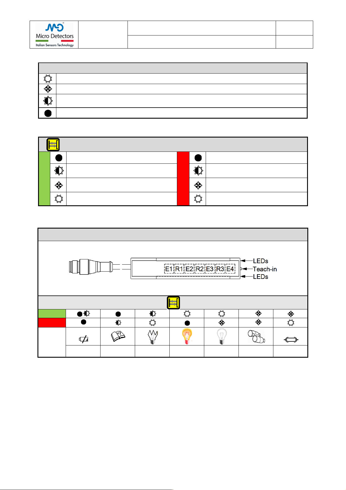
5.4 Display indications and diagnostics.
MEANINGS OF LEDs SIGNALLING MODES
!
Indication of full light and steady
!
Indication of low intensity or intermittently with fast periodic flashing
!
Indication of slow continuous flashing
!
Off
Tab.:13
LEDs INDICATIONS
GN
!
No power supply or below 5V.
Memory reading error.
RD
!
Light state.
No power supply.
!
Power supply below 16V.
Emission LEDs failed.
!
Memory reading error.
!
Alignment.
Outputs in short circuit
!
Alignment.
Some optics in Dark
!
Normal operation.
!
Many or all optics in the DARK
Fault or outputs in short circuit
Tab.:14
COMBINED INDICATIONS
GN
↑
RD
↓
STATUS
Power
Out
OFF or LOW
MEMORY
ERROR
FAULT
LIGHT
DARK
ALIGNEMENT
OVERLOAD
Tab.:15
!
!
!
!
!
!
!
M.D. Micro Detectors
Strada S. Caterina, 235
41122 Modena Italy
Tel. +39 059 420411
Fax +39 059 253973
www.microdetectors.com
CR0 SERIES
RETROREFLECTIVE AREA SENSOR
LANGUAGE
Installation and Operation Manual
ENGLISH
M.D. Micro Detectors
CAT8ECR1780101
14/16
!
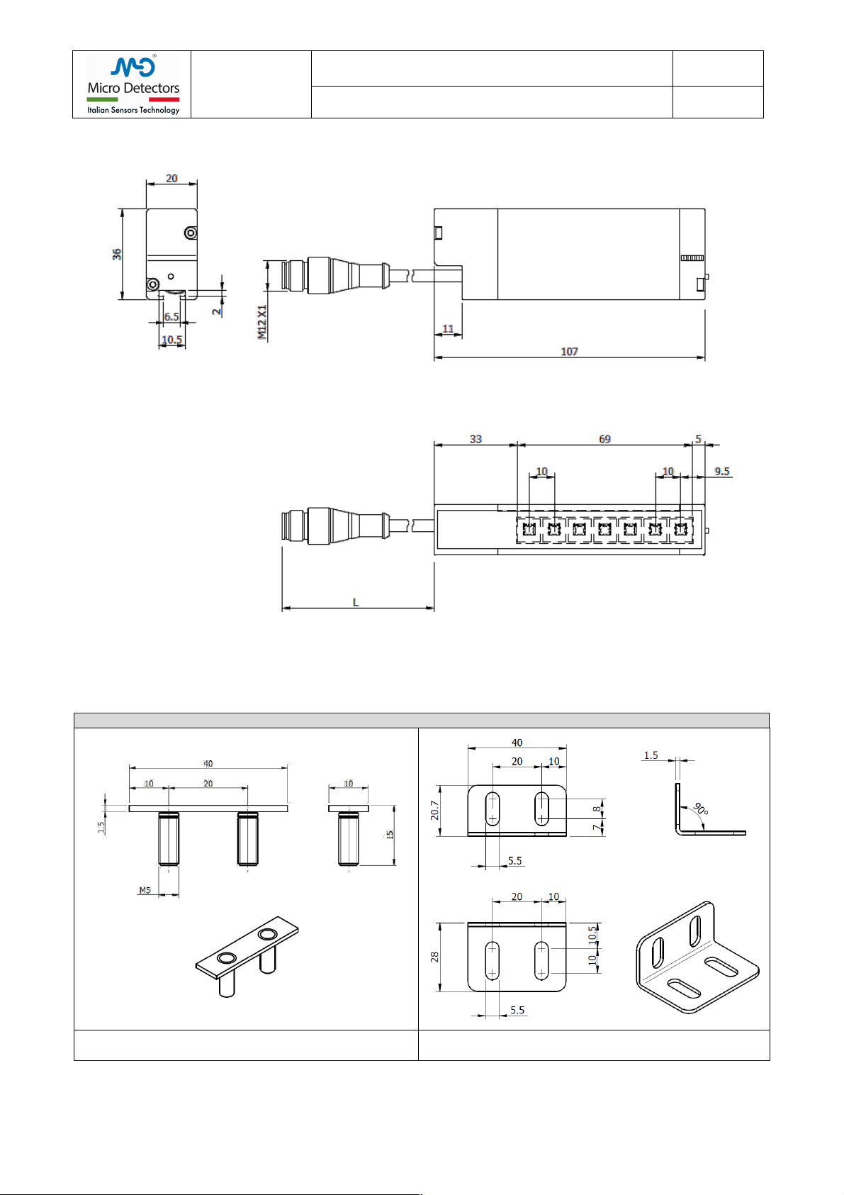
6.0 MECHANICAL DIMENSIONS OF LIGHT CURTAINS AND STANDARD ACCESSORIES
6.1 Mechanical dimensions of CR0/**-1V reflex curtains
!
Pict.: 1
Pigtail cable length L= 240mm
6.2 Standard Mounting accessories
One unit is supplied by type
Kit mounting accessories ST151
!
!
!
!
!
!
!
Pict.: 2
T-shaped insert, with two M5 nuts and two split washers.
Pict.: 3
L-shaped mounting bracket

!
M.D. Micro Detectors
Strada S. Caterina, 235
41122 Modena Italy
Tel. +39 059 420411
Fax +39 059 253973
www.microdetectors.com
CR0 SERIES
RETROREFLECTIVE AREA SENSOR
LANGUAGE
Installation and Operation Manual
ENGLISH
M.D. Micro Detectors
CAT8ECR1780101
15/16
!
7.0 INSTALLATION
Securing CR0 light curtains with accessories’ kit ST151
Place the T-shaped insert
Mount the L-shaped bracket on the
T-shaped insert
Secure light curtains to the wall
Pict.: 2
8.0 LIST OF AVAILABLE ACCESSORIES
M12 CONNECTORS, 4 POLES, WITH CABLE
CD12M/0B-020A1
M12 connector, straight, 4 poles, female, 2m PVC cable
CD12M/0B-050A1
M12 connector, straight, 4 poles, female, 5m PVC cable
CD12M/0B-100A1
M12 connector, straight, 4 poles, female, 10m PVC cable
M12 CONNECTORS, 4 POLES, WITH CABLE
CD12M/0B-050A5
M12 connector, straight, 4 poles, female, 5m PUR cable
CD12M/0B-100A5
M12 connector, straight, 4 poles, female, 10m PUR cable
M12 CONNECTORS, 5 POLES, WITH CABLE
CD12M/0H-050A5
M12 connector, straight, 5 poles, female, 5m PUR cable
CD12M/0H-100A5
M12 connector, straight, 5 poles, female, 10m PUR cable
STANDARD MOUNTING KIT FOR LIGHT CURTAINS
ST151
Kit with T-shaped insert with four M5 screws complete with nuts and washers and an L-shaped bracket
VIBRATION DAMPING SUPPORTS
ST 4V S
Kit of 4 vibration-damping supports
Tab.:16
9.0 PACKAGE CONTENT
Each package has the following content:
•A retroreflective area sensor.
•An accessories’ kits ST151 (T-shaped insert and L-shaped bracket)
•Reflector R106G
•Multilingual installation short manual.

!
M.D. Micro Detectors
Strada S. Caterina, 235
41122 Modena Italy
Tel. +39 059 420411
Fax +39 059 253973
www.microdetectors.com
CR0 SERIES
RETROREFLECTIVE AREA SENSOR
LANGUAGE
Installation and Operation Manual
ENGLISH
M.D. Micro Detectors
CAT8ECR1780101
16/16
!
10.0 CONTROL OF THE INSTALLED RETROREFLECTIVE AREA SENSOR
10.1 Purpose of controls.
The controls described here below are meant to ensure the functional and reliable performances required.
10.2 Preliminary controls before start-up
All devices must be correctly installed and well secured.
The maximum response time must be adequate to the application. Make sure that the sensor’s response time is compatible with the
specific application, detecting objects of minimum and maximum size, in different positions and, if possible, with even faster movements
compared to what the application allows.
Make sure that no optically interfering devices are in the visual field of the sensor. Make sure that other devices do not undergo
interferences by the emitted light.
Make sure that sensors are not exposed to any substance which might dirty or damage the optics.
Make sure that technical documentation is available for operators in charge of maintenance.
10.3 Controls device efficiency
State and efficiency of the device can be checked using a test stick, which must be detected in a way that is repetitive in time.
Make sure that there are no damages nor dirt on optical windows’ surface. Scratches and tarnished surfaces can negatively affect the
light curtain’s resolution.
If necessary, clean the optical surface with a humid antistatic cloth. Do not use any alcohol, nor solvents, nor abrasive substances.
Other manuals for CR0 Series
1
This manual suits for next models
7
Table of contents
Other Micro Detectors Accessories manuals


Popular Accessories manuals by other brands


Silver King
Silver King SKBB69 Technical manual and replacement parts list

Battery Tender
Battery Tender 030-1030-PS instruction manual

Xtant
Xtant XSC manual

SNAIGE
SNAIGE CD290 Series instruction manual

Braeburn
Braeburn 7490 Installer's guide

Electro-Sensors
Electro-Sensors Electry-Sentry 1 Installation & operation manual