MICRO-EPSILON Outdoor protective housing User manual

Operating Instructions
Outdoor Protective Housing for
thermoIMAGER TIM

MICRO-EPSILON
MESSTECHNIK
GmbH & Co. KG
Koenigbacher Str. 15
94496 Ortenburg / Germany
Tel. +49 (0) 8542 / 168-0
Fax +49 (0) 8542 / 168-90
e-mail [email protected]
www.micro-epsilon.com
Outdoor Protective Housing for thermoIMAGER TIM cameras

-Table of Contents 3-
Table of Contents
Table of Contents .............................................................................................................................................3
1General Information.................................................................................................................................5
1.1 Description ....................................................................................................................................... 5
1.2 Notes on CE Marking....................................................................................................................... 6
1.3 Unpacking, Included in Delivery....................................................................................................... 6
2Technical Data..........................................................................................................................................7
2.1 General Specifications ..................................................................................................................... 7
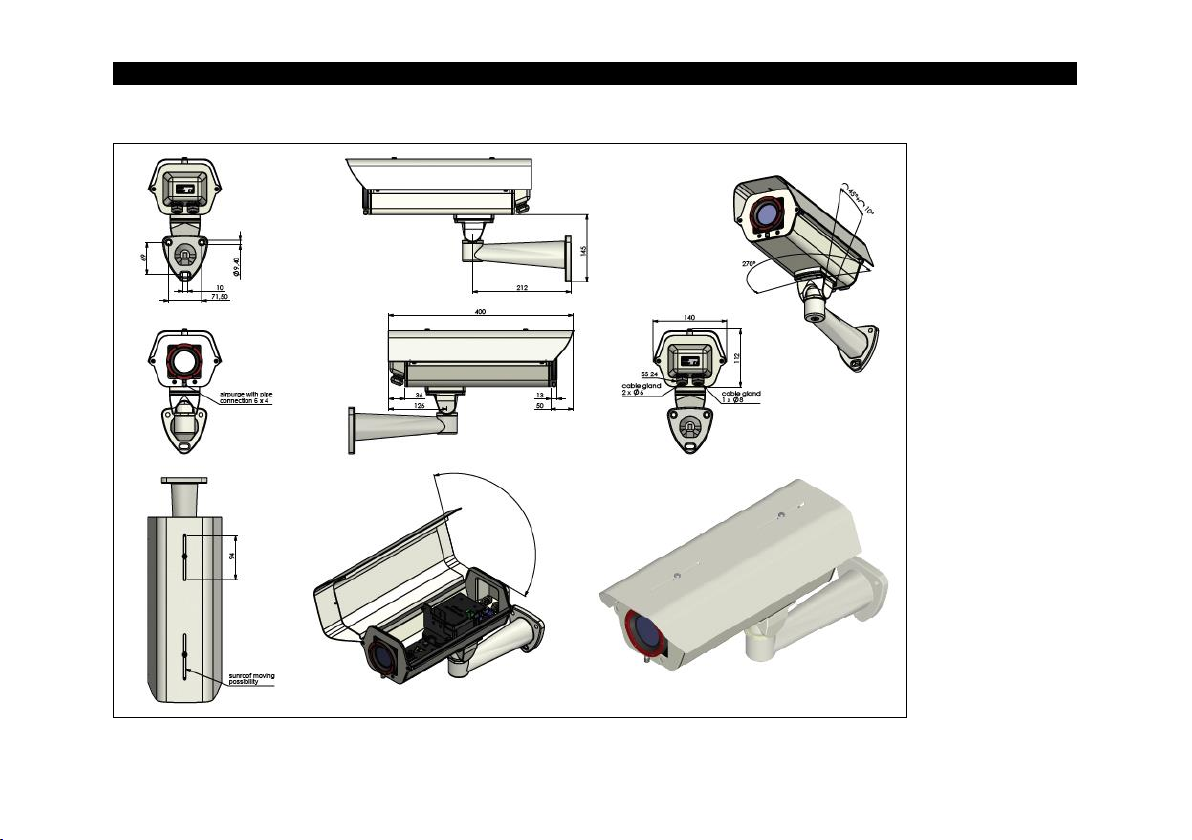
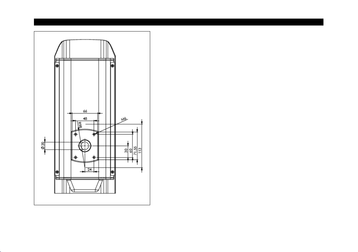
2.2 Dimensions....................................................................................................................................... 9
2.3 Electrical Connections.................................................................................................................... 11
2.4 Air Purge Collar.............................................................................................................................. 12
3Installation ..............................................................................................................................................13
3.1 Electrical Installation....................................................................................................................... 13
3.2 Mounting of the USB Server .......................................................................................................... 15

-Table of Contents 4-
3.3 Mounting of the TIM Camera.......................................................................................................... 17
3.4 Mounting of the thermometer TIM 8 and the thermoIMAGER TIM 40 Camera............................. 21
3.5 Mounting of thermoMETER CSL / thermoMETER CTL................................................................. 22
4Optional Accessoires ............................................................................................................................24
4.1 Industrial Process Interface (PIF)................................................................................................... 24
4.2 Wall Mount ..................................................................................................................................... 25
5Replacement of Protective Foil ............................................................................................................26
5.1 Disassembling Air Purge Collar ..................................................................................................... 26
5.2 Removing and Inserting the Protective Foil ................................................................................... 28
5.3 Cut the Protective Foil.................................................................................................................... 30
6Liability for Material Defects.................................................................................................................32

-General Information 5-
1 General Information
1.1 Description
Thank you for choosing the Outdoor protective housing.
The outdoor protective housing is an ideal complement for the TIM camera, the thermoMETER CSL, the
thermoMETER CTL and the USB server for applications with additional influences of different kinds. It
protects the devices among things like dirt, dust and moisture. The outdoor protective housing can be used
for any TIM camera (lenses up to 90 ° FOV). The integrated heating and the blower result in an extended
operating temperature.
Avoid abrupt changes of the ambient temperature.
Avoid mechanical violence –this may destroy the system (expiry of warranty).
If you have any problems or questions, please contact our service department.
Read the manual carefully before the initial start-up. The producer reserves the right to change
the herein described specifications in case of technical advance of the product.

-General Information 6-
1.2 Notes on CE Marking
The following apply to the Outdoor Protective Housing:
EU Directive 2014/30/EU
EU Directive 2011/65/EU, “RoHS“ category 11
Products which carry the CE mark satisfy the requirements of the EU directives cited and the relevant ap-
plicable harmonized European standards (EN). The measuring system is designed for use in industrial
environments.Die EU-Konformitätserklärung wird gemäß der EU-Richtlinie, Artikel 10, für die zuständige
Behörde zur Verfügung gehalten.
The EU Declaration of Conformity is available to the responsible authorities according to EU Directive,
article 10.
1.3 Unpacking, Included in Delivery
Protection housing with integrated heating incl. protection window or foil window and air purge collar
Operating Instructions

-Technical Data 7-
2 Technical Data
2.1 General Specifications
Temperature range
-40 °C … +50 °C
Heating
PTC heater (automatically starting at T < 15 °C) / fan for homogeneous
temperature distribution 1)
Power supply
24 V DC
Power
70 W
Protective window 2)
Germanium (Ge), zinc sulfide (ZnS), Borofloat or foil
Environmental rating
IP66
Air purge collar
Integrated
Air pressure
Absolute pressure 1.1 - 8 bar at 20 -100 l/min
Max. FOV
90 ° (HFOV)
Integrated additional
components
USB-Server Gigabit
Industrial Process interface (PIF)
Material
Aluminum
Weight
2 kg (with wall mount 2.5 kg)
FOV: Enlargement of the total measuring field at object level
HFOV: Horizontal enlargement of the total measuring field at object level

-Technical Data 8-
1) The fan is switched parallel to the heater. When the heater starts, the fan will also run. The heating is switched on
when the temperature falls below 15 °C (closing temperature) and switched off (opening temperature) at 25 °C (±5°C).
2) There is no protection window for the thermoMETER TIM 8 and the thermoIMAGER TIM 40.

-Technical Data 9-
2.2 Dimensions
Figure 1: Dimensions with wall mount, dimensions in mm, not to scale

-Technical Data 10-
Figure 2: Dimensions for wall mount, dimensions in mm, not to scale

-Technical Data 11-
2.3 Electrical Connections
Figure 3: Connection circuit board
Power supply
Industrial PIF
and USB server

-Technical Data 12-
2.4 Air Purge Collar
The lens must be kept clean at all times from dust, smoke, fumes and other contaminants in order to avoid
reading errors. These effects can be reduced by using an air purge collar. Make sure to use oil-free,
technically clean air only.
The needed amount of air (approx. 20 ... 100 l/ min.) depends on the application and the
installation conditions on-site.
Protective window
Description
Spectral range
Transmission 1)
Germanium
Protective window (50.8 x 3 mm/ Ge) for TIM QVGA-G7, TIM VGA-G7
7.9 µm
0.96
Protective window (50.8 x 3 mm/ Ge) for TIM 160, TIM QVGA, TIM QVGA-HD,
TIM 640
7.5-13 µm
0.92
Zinc sulfide
Protective window (50.8 x 3 mm/ ZnS) for TIM QVGA-G7, TIM VGA-G7
7.9 µm
0.93
Protective window (50.8 x 3 mm/ ZnS) for TIM 160, TIM QVGA, TIM QVGA-HD,
TIM 640
7.5-13 µm
0.91
Protective window (50.8 x 3 mm/ ZnS) for TIM 200, TIM 230 (appropriate for VIS
+ IR)
7.5-13 µm
0.91
Protective window (50.8 x 3 mm/ ZnS) for LT models of thermoMETER CTL, CSL
serie
7.5-13 µm
0.91
Borofloat
Protective window (50.8 x 3 mm/ Borofloat 33) for TIM M-1, TIM M-05
0.85-1.1 µm, 500-540 nm
0.92
1) The displayed values are standard values and can vary between different delivery units.

-Installation 13-
3 Installation
3.1 Electrical Installation
Loosen the two screws and open the outdoor protective housing, as shown in Figure 4.
Figure 4: Opening the housing

-Installation 14-
Inside the protective housing is the electronic circuit board, where all loads are connected (see Figure 3).
The heating element and the fan are already integrated and connected. To supply the outdoor protective
housing with voltage, you must connect a 24 V line. This is connected to the marked side of the board.
Observe the correct polarity and ensure that no voltage is present. The USB server and the industrial PIF are
connected to the board as shown and are supplied by 24 V.
To get the cables into the housing, you must loosen the two cable glands, as shown in Figure 6. On the left
side is a cable gland with 8 mm sealing insert and on the right is a cable gland with two 6 mm sealing inserts.
It is recommended to pull the Ethernet cable or the USB cable through the 8 mm sealing insert. The PIF
cable and the 24 V cable are passed through the two 6 mm sealing inserts.
Figure 5: Cable glands on the backside of the outdoor
protective housing
Cable gland 1
Cable gland 2
1 x 8 mm sealing insert
2 x 6 mm sealing insert
For Ethernet or USB
cable
For PIF cable and
24 V line
To get the Ethernet cable with a plug through the opening, you have to cut the rubber insert.

-Installation 15-
3.2 Mounting of the USB Server
Insert the USB server at a slanted angle to the designated disk (Figure 6). If necessary, remove the clip from
the USB server (Figure 7) and turn the USB server (Figure 6) until the clip is locked into the bracket
(Figure 8).
Figure 6: Insertion of the USB server into the provided board
Figure 7: USB server clip
Figure 8: USB server holding plate

-Installation 19-
Step 3: Mounting the TIM cameras
Figure 12: TIM 4xx/ 640/ 1M/ 05M
attachment
Figure 13: TIM 160 attachment
Figure 14: TIM 2xx attachment
Mount the TIM QVGA/ TIM QVGA-HD/ TIM 640/ TIM M-1/ TIM M-05 to the mounting plate using the supplied
1/4 x 3/8 UNC inch screw and a washer DIN125A-6,4 A2 (Figure 12).
Mount the TIM QVGA/ TIM QVGA-HD/ TIM 160 to the mounting plate using the supplied 1/4 x 3/8 UNC inch
screw and four washers DIN125A-6,4 A2 (Figure 13).
Mount the TIM 2xx to the mounting plate using the supplied 1/4 x 1 1/4 UNC inch screw, the distance sleeve
and one washer DIN125A-6,4 A2 (Figure 14).

-Installation 20-
After the camera is fully assembled, the mounting plate can be attached back to the outdoor protective
housing with the provided screw.
Figure 15: Fully assembled TIM camera on mounting
Figure 16: Fully assembled TIM camera in outdoor protective housing
Table of contents