MICRO-EPSILON boreCONTROL User manual

Measuring system for
internal wall inspection in bore holes
Instruction manual
boreCONTROL

MICRO-EPSILON
MESSTECHNIK
GmbH & Co. KG
Königbacher Straße 15
D-94496 Ortenburg
Tel. +49/8542/168-0
Fax +49/8542/168-90
email [email protected]
www.micro-epsilon.com
Certified according to DIN EN ISO 9001: 2008

boreCONTROL
Contents
1. Safety .......................................................................................................................................... 5
1.1 Symbols Used .................................................................................................................................. 5
1.2 Warnings........................................................................................................................................... 5
1.3 Notes on CE Identification................................................................................................................ 5
1.4 Proper Use........................................................................................................................................ 6
1.5 Proper Environment ......................................................................................................................... 6
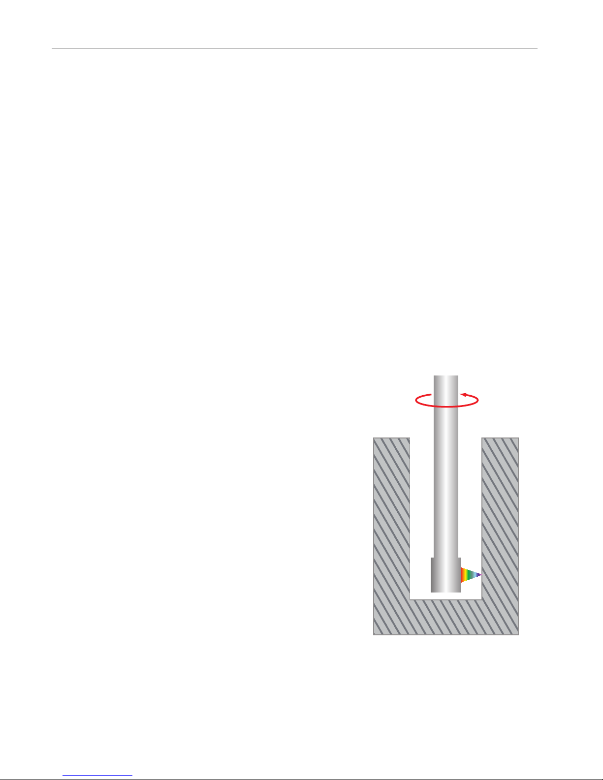
2. Functional Principle, Technical Data ......................................................................................... 6
2.1 Short Description.............................................................................................................................. 6
2.2 Measuring Setup .............................................................................................................................. 7
3. Delivery ....................................................................................................................................... 8
3.1 Supplied Items.................................................................................................................................. 8
3.2 Storage ............................................................................................................................................. 8
4. Mounting..................................................................................................................................... 8
4.1 Rotation Unit BCM2410.................................................................................................................... 8
4.2 Controller BCC2410 ......................................................................................................................... 9
4.3 IFC24x1........................................................................................................................................... 10
4.4 Electrical Connections BCC2410................................................................................................... 10
4.4.1 Power Supply ................................................................................................................................. 10
4.4.2 Rotation Unit BCM2410.................................................................................................................. 11
4.4.3 IFC 24x1.......................................................................................................................................... 11
4.4.4 RS232 ............................................................................................................................................. 11
4.5 Electrical Connections IFC24x1 ..................................................................................................... 12
4.5.1 Power Supply ................................................................................................................................. 12
4.5.2 Ethernet .......................................................................................................................................... 12
4.5.3 Rotation Unit ................................................................................................................................... 13
4.6 Mounting the Sensor Lance BCS241x-x ........................................................................................ 14
4.7 Dismounting the Sensor Lance BCS241x-x................................................................................... 15
5. Acquiring the Dark Signal........................................................................................................ 16
6. Warranty.................................................................................................................................... 17
7. Service, Repair ........................................................................................................................ 17
8. Decommissioning, Disposal ................................................................................................... 17
9. Declaration of Incorporation.................................................................................................... 18

boreCONTROL

Page 5
Safety
boreCONTROL
Safety1.
Knowledge of the operating instructions is a prerequisite for equipment operation.
Symbols Used1.1
The following symbols are used in the instruction manual.
CAUTION
Indicates a hazardous situation which, if not avoided, may result in
minor or moderate injury.
NOTICE
Indicates a situation which, if not avoided, may lead to property
damage.
Indicates a user action.
iIndicates a user tip.
Warnings1.2
Connect or disconnect controller components only, if the controller is off.
Danger of injury>
Damage to or destruction of the controller>
The power supply and the display/output device must be connected in accordance with
the safety regulations for electrical equipment.
Danger of injury>
Damage to or destruction of the controller>
The power supply may not exceed the specified limits.
Danger of injury>
Damage to or destruction of the controller>
Avoid shock and vibration to the sensor and controllers.
Damage to or destruction of the sensor and controllers>
Avoid exposure to aggressive materials (washing agent, penetrating liquids or similar) on
the sensor lance.
Damage to or destruction of the sensor>
Failure of the measuring device>
Notes on CE Identification1.3
The following applies to the measuring system boreCONTROL:
EMC regulation 2004/108/EC-
Machinery Directive 2006/42/EC-
Products which carry the CE mark satisfy the requirements of the EMC regulation
2004/108/EC ‘Electromagnetic Compatibility’ and the European standards (EN) listed
therein. The EC declaration of conformity is kept available according to EC regulation,
article 10 by the authorities responsible at
MICRO-EPSILON MESSTECHNIK GmbH & Co. KG
Koenigbacher Straße 15
D-94496 Ortenburg
The system is a not automatically operable device (component). An EC declaration of
conformity or CE identification is therefore not issued by Machinery Directive.
CAUTION
NOTICE

Page 6
Functional Principle, Technical Data
boreCONTROL
Proper Use1.4
The system is designed for industrial use in automated manufacturing and machine-
monitoring. It is used for internal wall inspection in bore holes, recesses, depressions,
notches and hollows
The system may only be operated within the limits specified in the technical data, see-
data sheet.
The system should only be used in such a way that in case of malfunction or failure-
personnel or machinery are not endangered.
Additional precautions for safety and damage prevention must be taken for safety--
related applications.
Proper Environment1.5
Protection class controller: IP 40-
Operating temperature: +10 to +40 °C (+50 to +104 °F)-
Storage temperature: -20 to +70 °C (-4 to +158 °F)-
Humidity: 5 - 95 % (non condensing)-
Ambient pressure: atmospheric pressure-
EMC: According to EN 61000-6-3: 2007-
EN 61000-6-2: 2005
Functional Principle, Technical Data2.
Short Description2.1
The rotating confocal miniature sensor mea-
sures the inner surface of rotational solids e.g.
diameter, roundness, concentricity, tapering
and straightness. The beam path is applied in
the radial direction.
Measured data conditioning is performed us-
ing a compact controller which enables data
acquisition of up to 30 kHz (standard 2 kHz).
Due to the absolute measuring principle, fluc-
tuating diameters in the measuring range in a
measuring process do not pose any problems.
A complex attached precision ball bearing sys-
tem with integrated optical coupling and servo
motor provides the necessary rotation stability.
Another compact controller controls the move-
ments of the rotation unit.
Measuring principle for internalFig. 1
wall inspection

Page 7
Functional Principle, Technical Data
boreCONTROL
Measuring Setup2.2
6
USB 3/4 USB 5/6
Digital I/O Analog I/O
Firewire / IEEE1394
1 2 3
USB 1/2
COM1
Power
IPC-4
VGA
LAN1 LAN2
DVI
Relais Remote
7
Sensor
810
SyncIn / TrigIn
GND
Shield
SyncOut
GND
Error 1
GND
Shield
Error 2
GND
HLL
24 VDC
GND
Shield
U out
GND U
Shield
I out
GND I
Power
Digital I/O
RS422Encoder
Analog Out
confocalDT
Intensity >max
Intensity <min
Intensity ok
Out of range
Midrange
In range
Power On
External light
source
Status In
Ethernet External
light sourceSensor
RS422
Encoder
Dark reference
STATUS
PS2020
230 VAC
PE
N L
PS2020
4
5
2
3
1
IFC
+24V DC GND RS232
boreCONTROL
9
1 Sensor controller IFC24x1
2 Optical fiber (Sensor cable) S2410-x
3 Data cable SC2410-03
4 Rotation unit BCM2410
5 Sensor lance with confocal sensor BCS2412-4,5/10
6 Power supply PS2020
7 boreSYSTEM with plug and play BC-IPC, optional
measurement software
8 Synchronization cable SC2410-0.5
9 Controller, boreCONTROL BCC2410
10 LAN cable

Page 8
Delivery
boreCONTROL
Delivery3.
Supplied Items3.1
1 Sensor controller IFC24x1
1 BCR2410 consisting of BCM2410 and controller BCC2410
1 Sensor lance BCS241x-x with fitting calibration ring
1 Optical fiber (sensor cable) S2410-x
1 Data cable SC2410-03
1 LAN cable
1 Synchronization cable SC2410-0.5
1 Serial cable RS232
1 CD with demo software and boreCONTROL-SDK
1 Disassembly aid
Optional Accessories, separate packed:
1 Power supply PS2020 1 boreSYSTEM
Remove the parts of the system carefully from the packaging and transport them in
such a way that they are not damaged.
Check for completeness and shipping damages immediately after unpacking. In
case of damage or missing parts, please contact the manufacturer or supplier.
Storage3.2
Storage temperature: 0 °C up to +75 °C
Relative humidity: 0 - 95 % (non-condensing)
Mounting4.
The sensors of the series BCS241x-x are optical sensors, which are used to measure in
μm-range.
iHandle optical sensors with care during mounting and operation.
Rotation Unit BCM24104.1
ø 3.3 (.13)
ø 8.0 (.31)
ø45
(1.77)
50/80 (1.97/3.15) 162 (6.38)
Mounting area
Mount the rotation unit with a mounting
adapter, see Fig. 3.
This type of sensor mounting offers maxi-
mum reliability because the rotation unit is
clamped around its cylindrical housing. It is
absolutely necessary in difficult installation
environments, e.g. on machines, produc-
tion plants etc.
Dimensional drawing rotation unit with sensor lance, dimensions in mm (inches)Fig. 2
CAUTION
Danger by detecting and
winding the hair, the clo-
thes. Wear a hair net and
tight clothing with rotary
rotation unit.
Legend:
mm
(inches)

Page 9
Mounting
boreCONTROL
A-A
A
A
M5
M5
ø 61
(2.40)
approx. 88.5 (3.48)
17
(.67)
10
(.39)
20 (.79)
16 (.63)
30 (1.18)
ø 45 (1.77)
Fig. 3 Dimensional drawing mounting adapter, dimensions in mm (inches), not to scale
Controller BCC24104.2
Keep the connectors free in mounted position.
Mount the controller on a DIN rail type TS35.
R5
84 (3.31)
76.15 (3.00)
83.7 (3.30)
120 (4.72)
+24V DC GND RS232
IFCSensor
boreCONTROL
Dimensional drawing BCC2410, dimensions in mm (inches), not to scaleFig. 4

Page 10
Mounting
boreCONTROL
IFC24x14.3
Keep the function keys, connectors and LEDs free in mounted position.
Mount the controller on a DIN rail type TS35.
218 (8.58)
120 (4.72)
(Feets can be removed)
76.2 (3.00)
81.2 (3.20)
Other cables:
less space
fastener
Sensor cable
R
30
appr.
63 (2.48)
DIN rail
appr. 75 (2.95)
Dimensional drawing IFC24x1Fig. 5
Electrical Connections BCC24104.4
Power Supply4.4.1
The plug-in terminal strip is designed for a conductor cross section of 0.25 mm² to 1.0
mm². The terminal strip is mounted on the controller with two screws and can be re-
moved for wiring or a fast controller change.
Connect the inputs “24 V” and “0 V” to a 24 V power supply.
MICRO-EPSILON recommends to use the optionally available power supply PS2020 for
the controller. Features: DIN rail mounting, input 230 VAC, output 24 VDC/2.5 A.
+24V DC GND RS232
IFCSensor
boreCONTROL
PS2020
230 VAC
PE
N L
Power supply of the boreCONTROL with a PS2020Fig. 6
Legend:
mm
(inches)

Page 11
Mounting
boreCONTROL
Rotation Unit BCM24104.4.2
Connect the controller (connector “Sensor“) with the rotation unit. Please use the
SC2410-03 cable.
+24V DC GND RS232
IFCSensor
boreCONTROL
Rotation unit connect to the boreCONTROLFig. 7
IFC 24x14.4.3
Connect the controller (connector “IFC“) with the IFC24x1. Use the SC2410-0,5
cable.
boreCONTROL
Sensor
+24V DC GND RS232
SyncIn / TrigIn
GND
Shield
SyncOut
GND
Error 1
GND
Shield
Error 2
GND
HLL
24 VDC
GND
Shield
U out
GND U
Shield
I out
GND I
Power
Digital I/O
RS422Encoder
Analog Out
confocalDT
Intensity >max
Intensity <min
Intensity ok
Out of range
Midrange
In range
Power On
External light
source
Status In
Ethernet External
light sourceSensor
RS422
Encoder
Dark reference
STATUS
IFC
Sensor controller connected to the boreCONTROLFig. 8
RS2324.4.4
Connect the controller (connector “RS232“) with the PC. Use a standard interface
cable.
PIN No.
9-pin Sub-D Assignment
+24V DC GND RS232
IFCSensor
boreCONTROL
USB3/4 USB5/6
DigitalI/O AnalogI/O
Firewire/ IEEE1394
1 2 3
USB1/2
COM1
Power
IPC-4
VGA
LAN1 LAN2
DVI
Relais Remote
2 TxD
3 RxD
5 GND
Via the RS232 interface, the instruc-
tions of the motor control are trans-
ferred to the rotation unit.
Baud rate: 9.6 kBaud. Data format:
8 data bits, no parity, one stop bit
(8,N,1).
The reference grounds (GND) of con-
troller and receiver (e.g. PC or PLC)
must be connected.

Page 12
Mounting
boreCONTROL
Electrical Connections IFC24x14.5
Power Supply4.5.1
Connect the inputs “24 VDC” and “GND” to a 24 V power supply.
MICRO-EPSILON recommends to use the optionally available power supply PS2020 for
the controller. Features: DIN rail mounting, input 230 VAC, output 24 VDC/2.5 A.
SyncIn / TrigIn
GND
Shield
SyncOut
GND
Error 1
GND
Shield
Error 2
GND
HLL
24 VDC
GND
Shield
U out
GND U
Shield
I out
GND I
Power
Digital I/O
RS422Encoder
Analog Out
confocalDT
Intensity >max
Intensity <min
Intensity ok
Out of range
Midrange
In range
Power On
External light
source
Status In
Ethernet External
light sourceSensor
RS422
Encoder
Dark reference
STATUS
PS2020
230 VAC
PE
N L
Power supply of the boreCONTROL with a PS2020Fig. 9
Ethernet4.5.2
Connect the controller (connector “Ethernet“) with the PC. Use a standard LAN
cable.
USB 3/4 USB 5/6
Digital I/O Analog I/O
Firewire / IEEE1394
1 2 3
USB 1/2
COM1
Power
IPC-4
VGA
LAN1 LAN2
DVI
Relais Remote
SyncIn / TrigIn
GND
Shield
SyncOut
GND
Error 1
GND
Shield
Error 2
GND
HLL
24 VDC
GND
Shield
U out
GND U
Shield
I out
GND I
Power
Digital I/O
RS422Encoder
Analog Out
confocalDT
Intensity >max
Intensity <min
Intensity ok
Out of range
Midrange
In range
Power On
External light
source
Status In
Ethernet External
light sourceSensor
RS422
Encoder
Dark reference
STATUS
Ethernet connection between sensor controller and boreSYSTEMFig. 10

Page 13
Mounting
boreCONTROL
Rotation Unit4.5.3
Connect the controller (connector “Sensor“) with the rotation unit. Use the
S2410-x cable.
SyncIn / TrigIn
GND
Shield
SyncOut
GND
Error 1
GND
Shield
Error 2
GND
HLL
24 VDC
GND
Shield
U out
GND U
Shield
I out
GND I
Power
Digital I/O
RS422Encoder
Analog Out
confocalDT
Intensity >max
Intensity <min
Intensity ok
Out of range
Midrange
In range
Power On
External light
source
Status In
Ethernet External
light sourceSensor
RS422
Encoder
Dark reference
STATUS
Connected light source on the rotation unitFig. 11

Page 14
Mounting
boreCONTROL
Mounting the Sensor Lance BCS241x-x4.6
The removable sensor lance allows fast change of the miniature confocal sensor. Subse-
quently, the sensor mounting is described.
Carefully remove the sensor lance from the packing.
Move the sensor into the rotation
unit.
Turn the lock ring 90 degrees to the
left.
Remove the disassembly aid in hori-
zontal direction.
Rotate the sensor until the marks on
the sensor and the rotation unit are
on opposite side.
The sensor lance snaps in place of the
rotation unit.
Now the sensor is mounted in the rota-
tion unit.
If you have finished the sensor change, measure the dark signal in the sensor, see
Chap. 5.

Page 15
Mounting
boreCONTROL
Dismounting the Sensor Lance BCS241x-x4.7
The removable sensor lance allows fast change of a miniature confocal sensor. Subse-
quently, the sensor dismounting is described.
Slide the disassembly aid in hori-
zontal direction on the sensor.
Lock ring
Sensor, confocal
Disassembly aid
Turn the lock ring 90 degrees to
the right.
Now the sensor is locked in the disas-
sembly aid.
Extract the disassembly aid with
the sensor vertically of the rota-
tion unit.
Carefully insert the disassembly
aid with sensor lance into the
packing.

Page 16
Acquiring the Dark Signal
boreCONTROL
5. Acquiring the Dark Signal
The dark signal of the sensor represents an intrinsic offset level generated by parasitic
reflections inside the controller, which must be taken into account for the controller to
be able to operate correctly. The level of the dark signal depends on the sampling rate.
The dark signal should be acquired at all sampling rates in order to be able to subtract
it while the controller is measuring. A dark signal acquisition is performed during adjust-
ment by the manufacturer, but must be repeated at regular intervals.
If you change the light intensity at the external light source or you change the sen-
sor, you have to repeat the dark signal measuring.
iAfter each sensor change the dark signal has to be measured for the first time.
The dark signal compensation is described in the software manual.

Page 17
Warranty
boreCONTROL
Warranty6.
All components of the device have been checked and tested for perfect function in the
factory. In the unlikely event that errors should occur despite our thorough quality con-
trol, this should be reported immediately to MICRO-EPSILON.
The warranty period lasts 12 months following the day of shipment. Defective parts, ex-
cept wear parts, will be repaired or replaced free of charge within this period if you return
the device free of cost to MICRO-EPSILON. This warranty does not apply to damage
resulting from abuse of the equipment and devices, from forceful handling or installation
of the devices or from repair or modifications performed by third parties.
No other claims, except as warranted, are accepted. The terms of the purchasing
contract apply in full. MICRO-EPSILON will specifically not be responsible for eventual
consequential damages. MICRO-EPSILON always strives to supply the customers with
the finest and most advanced equipment. Development and refinement is therefore per-
formed continuously and the right to design changes without prior notice is accordingly
reserved.
For translations in other languages, the data and statements in the German language
operation manual are to be taken as authoritative.
Service, Repair7.
In the case of a defect on the system, please
send the affected parts for repair or exchange.
In the case of faults whose causes are not
clearly recognisable, please always send the
complete measuring system.
MICRO-EPSILON Messtechnik
GmbH & Co. KG
Königbacher Str. 15
D-94496 Ortenburg
Tel. +49/8542/168-0
Fax: +49/8542/168-90
www.micro-epsilon.com
Decommissioning, Disposal8.
Disconnect all power supply and output cables on both controllers.
Disconnect all interface cables between both controllers and PC or PLC.
The boreCONTROL is produced according to the directive 2002/95/EC („RoHS“). The
disposal is done according to the legal regulations (see directive 2002/96/EC).

Declaration of Incorporation9.
Declaration of Incorporation according to the
EC Machinery Directive 2006/42/EC, Appendix II B
We hereby declare that the following partly completed machinery
Machine design: boreCONTROL
Type designation: BCM2410 / BCC2410
Article: 7111116 / 2424001
- meets - as far as the scope of supply makes it possible - the basic requirements of the
Machinery Directive 2006/42/EC and the EMC Directive 2004/108/EC.
Applied harmonized EN standards:
EN ISO 14121-1 | Safety of machinery - Risk assessment-
EN 55011: 2007 | Group 1 Class A - Electromagnetic disturbance characteristics --
Limits and methods of measurement
EN 61326-1: 2006 | EMC requirements - Part 1: General requirements-
We also declare that the special technical documentation for this partly completed ma-
chine has been created in accordance with Annex VII, part B, and commit ourselves to
forward this to the market surveillance authorities on request.
The commissioning of this partly completed machine is prohibited until the partly com-
pleted machine has been installed in a machine that meets the requirements of
EC Machinery Directive and for which an EC declaration of conformity according to An-
nex II A exists.
Ortenburg, 27 February 2012
Dipl.-Ing. (FH) Florian Ehrnböck
R&D Design Engineering
MICRO-EPSILON MESSTECHNIK
GmbH & Co. KG
Königbacher Straße 15
D-94496 Ortenburg, Germany
Tel.: 08542/168-0
Fax: 08542/168-90
www.micro-epsilon.com
Certified according to DIN EN ISO 9001: 2008


MICRO-EPSILON MESSTECHNIK GmbH & Co. KG
Königbacher Str. 15 · 94496 Ortenburg / Germany
Tel. +49 (0) 8542 / 168-0 · Fax +49 (0) 8542 / 168-90
*X9751231-B02*
X9751231-B021012HDR
Table of contents
Other MICRO-EPSILON Industrial Electrical manuals
Popular Industrial Electrical manuals by other brands

Murata
Murata GRM033R61E681KA01 Series Reference sheet

Murata
Murata GRM1885C1H222JA01 Series Reference sheet

Murata
Murata GJM1555C1H2R1BB01 Series Reference sheet

Murata
Murata GRM0225C1E6R4BA03 Series Reference sheet

Murata
Murata GRM32ER60G227ME05 Series Reference sheet

Murata
Murata GJM0335C1H2R9BB01 Series Reference sheet

VARISCO
VARISCO JE Series Instructions for the use and maintenance

Murata
Murata GRM219C80J106ME39 Series Reference sheet

Control Techniques
Control Techniques Unidrive Size 2 Installation sheet

Murata
Murata GRM0335C1H5R3DA01 Series Reference sheet

Murata
Murata GRM2195C1H103JA01 Series Reference sheet

Murata
Murata GRM0335C1H3R2CA01 Series Reference sheet