MICRO-EPSILON OT-3-GL User manual

MICRO-EPSILON Eltrotec GmbH
Manfred-Wörner-Straße 101 · 73037 Göppingen / Germany
Tel. +49 (0) 7161 / 98872-300 · Fax +49 (0) 7161 / 98872-303
for colorSENSOR
LT-1-LC-20
LT-3-HE
LT-3-LU
OT-3-MA
OT-3-GL
OT-3-HR
OT-3-LD
Instruction Manual
RS232 Ethernet Converter

RS232 Ethernet Converter for colorSENSOR
MICRO-EPSILON Eltrotec GmbH
Manfred-Wörner-Straße 101
73037 Göppingen / Germany
Tel. +49 (0) 7161 / 98872-300
Fax +49 (0) 7161 / 98872-303
e-mail [email protected]
www.micro-epsilon.com
Certied acc. to DIN EN ISO 9001: 2008

RS232 Ethernet Converter
Contents
1. Safety ........................................................................................................................................ 5
1.1 Symbols Used ................................................................................................................................................. 5
1.2 Warnings.......................................................................................................................................................... 5
1.3 Notes on CE Identification............................................................................................................................... 6
1.4 Proper Use....................................................................................................................................................... 6
1.5 Proper Environment......................................................................................................................................... 7
2. Functional Principle, Technical Data ....................................................................................... 7
2.1 Short Description............................................................................................................................................. 7
2.2 Structure of the System ................................................................................................................................... 8
2.3 Functions ......................................................................................................................................................... 8
2.4 Technical Data ................................................................................................................................................. 9
3. Delivery ................................................................................................................................... 10
3.1 Unpacking...................................................................................................................................................... 10
3.2 Storage .......................................................................................................................................................... 10
4. Mounting................................................................................................................................. 11
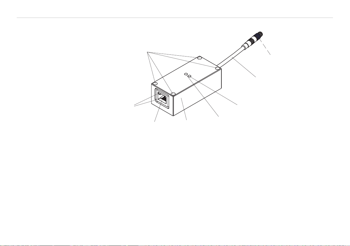
4.1 RS232 Ethernet Converter............................................................................................................................. 11
4.2 Mounting Steps.............................................................................................................................................. 12
4.3 Pin Assignment.............................................................................................................................................. 13
4.4 LEDs on Converter ........................................................................................................................................ 14
5. Warranty.................................................................................................................................. 15
6. Service, Repair ...................................................................................................................... 15
7. Decommissioning, Disposal ................................................................................................. 15
Appendix
A 1 Optional Accessories............................................................................................................. 16
A 2 Software ................................................................................................................................. 16

RS232 Ethernet Converter

Page 5
Safety
RS232 Ethernet Converter
1. Safety
The handling of the system assumes knowledge of the instruction manual.
1.1 Symbols Used
The following symbols are used in the instruction manual.
CAUTION Indicates a hazardous situation which, if not avoided, may result in death or serious
injuries.
NOTICE
Indicates a hazardous situation which, if not avoided, may result in minor or moderate
injuries.
Indicates a user action.
iIndicates a user tip.
1.2 Warnings
Connect the electrical components of the RS232 converter only when it is disconnected from the power sup-
ply.
> Damage to or destruction of the RS232 converter
Avoid shock and vibration to the RS232 converter.
> Damage to or destruction of the RS232 converter
Protect the cable against damage.
> Data loss
NOTICE

Page 6
Safety
RS232 Ethernet Converter
1.3 Notes on CE Identication
The following applies to the RS232 Ethernet converter: EMC regulation 2004/108/EC
Products which carry the CE mark satisfy the requirements of the EMC regulation 2004/108/EC ‘Electromag-
netic Compatibility’ and the European standards (EN) listed therein. The EC declaration of conformity is kept
available according to EC regulation, article 10 by the authorities responsible at
MICRO-EPSILON Eltrotec GmbH
Manfred-Wörner-Straße 101
73037 Göppingen / Germany
The RS232 Ethernet converter is designed for use in industrial and residential areas and satisfies the require-
ments of the standard
- EN 60947-5-2: 2007
The RS232 converter satisfies the requirements if they comply with the regulations described in the instruc-
tion manual for installation and operation.
1.4 Proper Use
The RS232 Ethernet converter allows sensors with serial interface to connect to a local network via Ethernet
bus.
- The system may only be operated within the limits specied in the technical data, see 2.4.
- Use the system in such a way that in case of malfunctions or failure personnel or machinery are not endan-
gered.
- Take additional precautions for safety and damage prevention for safety-related applications.

Page 7
Functional Principle, Technical Data
RS232 Ethernet Converter
1.5 Proper Environment
- Protection class: IP 50
- Operating temperature: -25 °C ... +65 °C (-13 ... +149 °F)
- Storage temperature: -25 °C ... +65 °C (-13 ... +149 °F)
- Humidity: 20 - 80 % relative humidity (non-condensing)
- Ambient pressure: Atmospheric pressure
- EMC: Acc. to EN 60947-5-2: 2007
2. Functional Principle, Technical Data
2.1 Short Description
The RS232 converter is used to expand the existing serial interfaces of many sensors to allow the integra-
tion into a local network or the Internet. This RS232 Ethernet converter thus enables the circumvention of the
length limitation of serial cables.
Further advantages:
1 Possibility of combining: Several sensors can be controlled via a network by only a PC.
2 Possibility of distribution: A sensor can be controlled over the entire network from different PC.
The adapter is based on the versatile XPortTM module, which unites high efficiency in a small dimension. The
range of features of this highly integrated Device servers contains likewise the possibility of depositing user
specific web pages. The wide range of setting options allows you to adjust the module to many user sce-
narios.

Page 8
Functional Principle, Technical Data
RS232 Ethernet Converter
2.2 Structure of the System
Aluminum
housing,
anodized in blue
Attachment options
RJ45 Ethernet
interface-
PUR cable
LED yellow:
Serial activity LED (TxD)
LED yellow:
Serial activity LED (RxD)
2x duo LED green/orange:
Ethernet activity and status LED
4-pin. connectorRundstecker
Binder series 707
2.3 Functions
- RJ45 Ethernet connector for connecting network cables (CAT5)
- Ethernet activity and status LED (2x duo LED green/orange)
- Serial activity and status LED (2x LED yellow)
- Power supply via colorSENSOR
- Reverse polarity via 4-pin. connector 707 M5 (CAB-M5-4P-St-ge; 2m-PVC; RJ45-Bu-Eth)

Page 9
Functional Principle, Technical Data
RS232 Ethernet Converter
2.4 Technical Data
Model RS232 Ethernet converter
CAB-M5-4P-St-ge; 2m-PVC; RJ45-Bu-Eth
Power supply +12 VDC ... +30 VDC
Current consumption max. 200 mA
Data rate 9600 Baud, 19200 Baud, 38400 Baud
Operating temperature -25 °C ... +65 °C (-13 ... +149 °F)
Storage temperature -25 °C ... +65 °C (-13 ... +149 °F)
Protection class IP 50
Housing material Aluminum, black anodized
Housing dimensions 70 mm x 32 mm x 25 mm
Electrical connection 4-pin. connector Binder series 707 M5
Cable length 2000 mm
Converter RS232/Ethernet
Elektromagnetic compatibility (EMC) EN 60947-5-2: 2007

Page 10
Delivery
RS232 Ethernet Converter
3. Delivery
3.1 Unpacking
1 RS232 Ethernet converter
1 Instruction manual
1 CD including “Deviceinstaller“
Check the delivery for completeness and shipping damage immediately after unpacking.
In case of damage or missing parts, please contact the manufacturer or supplier.
You will find optional accessories in appendix, see Chap. A 1.
3.2 Storage
Storage temperature: -25 - + 65 °C (-13 ... +149 °F)
Humidity: 20 up to 80 % relative humidity (non-condensing)

Page 11
Mounting
RS232 Ethernet Converter
4. Mounting
4.1 RS232 Ethernet Converter
70 (2.76)
25 (0.98)
3
(.12)
3 (.12)
ø 4.5 (.18 dia. (4x))
0.5 x 45° (.02 all around circumferential)
25 (0.98)
Fig. 1 Dimensional drawing CAB-M5-4P-St-ge; 2m-PVC; RJ45-Bu-Eth
Dimensions in mm, not to scale

Page 12
Mounting
RS232 Ethernet Converter
4.2 Mounting Steps
Connect a sensor of the colorSENSOR OT series 1 to the 4-pin connector Binder series 707 of RS232
Ethernet converter.
Now connect a LAN cable with RJ45 connector to the Ethernet port on the PC.
Now start the PC.
PC
RS232 Ethernet converter
CAB-M5-4P-St-ge; 2m-PVC; RJ45-Bu-Eth
colorSENSOR OT-3
1
series
RJ45 Ethernet interface
LAN cable with RJ45 connector
PUR cable with
4-pin. connector Binder series 707
Fig. 2 Connection diagram
1) Alternatively, the colorSENSOR
LT-1-LC-20, LT-3-HE or LT-3-LU

Page 13
Mounting
RS232 Ethernet Converter
4.3 Pin Assignment
Pin Assignment
1+24 VDC (+Ub, OUT)
2GND (0 V)
3RxD
4TxD
Fig. 3 Assignment 4-pin. connector
Binder series 707
View on solder pin side male cable connector

Page 14
Mounting
RS232 Ethernet Converter
4.4 LEDs on Converter
1
2
3
4
3
4
Fig. 4 Display elements on converter Fig. 5 View on Ethernet interface on converter
LED Color Designation Meaning
1RxD yellow RxD Serial activity LED / receive data
2TxD yellow TxD Serial activity LED / send data
342x duo LED green/orange - Ethernet activity and status LED

Page 15
Warranty
RS232 Ethernet Converter
5. Warranty
All components of the device have been checked and tested for perfect function in the factory. In the unlikely
event that errors should occur despite our thorough quality control, this should be reported immediately to
MICRO-EPSILON Eltrotec.
The warranty period lasts 12 months following the day of shipment. Defective parts, except wear parts, will be
repaired or replaced free of charge within this period if you return the device free of cost to MICRO-EPSILON
Eltrotec. This warranty does not apply to damage resulting from abuse of the equipment and devices, from
forceful handling or installation of the devices or from repair or modifications performed by third parties.
No other claims, except as warranted, are accepted. The terms of the purchasing contract apply in full.
MICRO-EPSILON Eltrotec will specifically not be responsible for eventual consequential damages. MICRO-
EPSILON Eltrotec always strives to supply the customers with the finest and most advanced equipment. De-
velopment and refinement is therefore performed continuously and the right to design changes without prior
notice is accordingly reserved. For translations in other languages, the data and statements in the German
language operation manual are to be taken as authoritative.
6. Service, Repair
In the event of a defect on the RS232 Ethernet
converter, please send us the RS232 Ethernet con-
verter for repair or exchange.
In the case of faults the cause of which is not clear-
ly identifiable, the whole RS232 Ethernet converter
must be sent back to
MICRO-EPSILON Eltrotec GmbH
Manfred-Wörner-Straße 101
73037 Göppingen / Germany
Tel: +49 (0) 7161 / 98872-300
Fax: +49 (0) 7161 / 98872-303
www.micro-epsilon.com
7. Decommissioning, Disposal
Disconnect all cables from the RS232 Ethernet converter.
The RS232 Ethernet converter is produced according to the direction 2011/65/EU, „RoHS“.
Do the disposal according to the legal regulations (see directive 2002/96/EC) EG).

Page 16
Appendix | Optional Accessories
RS232 Ethernet Converter
Appendix
A 1 Optional Accessories
Designation Description Article number
CAB-RJ45-Eth; 2m-PVC-Cat5e; RJ45-Eth Ethernet connection cable, 2 m long 11294232
CAB-RJ45-Eth; 5m-PVC-Cat5e; RJ45-Eth Ethernet connection cable, 5 m long 11293257
CAB-RJ45-Eth; 10m-PVC-Cat5e; RJ45-Eth Ethernet connection cable, 10 m long 11293702
CAB-RJ45-Eth; 20m-PVC-Cat5e; RJ45-Eth Ethernet connection cable, 20 m long 11234419
Connector cross Ethernet; 0.5 m Ethernet connector including crossed
Ethernet connection cable 0.5 m
11293227
A 2 Software
The configuration of the RS232 Ethernet converter takes places uniquely in connecting the RS232 Ethernet
converter to the sensor and the connection to the network.
Relevant settings, like the adjustment of the baud rate to those of the sensor and the assignment of the IP
address, can be made by the network administrator using the supplied “Deviceinstaller“ program with a com-
fortable user interface.
The RS232 Ethernet converter makes it possible to connect the sensor via the TCP/IP protocol.
The RS232 Ethernet converter is based on the Lantronix XPort module.
In order to parameterize the RS232 converter (assignment of IP address, setting of baud rate of 19200), the
free made available software (“DeviceInstaller“) of Lantronix®, Inc. can be loaded under
http://www.lantronix.com/support/downloads/?p=DEVICEINSTALLER
The DeviceInstaller is based on the „.NET„ framework from Microsoft.
A detailed instruction manual of the software “DeviceInstaller“ can be ordered by Lantronix ®, Inc.
The settings remain also after a hardware reset.

Page 17
Appendix | Software
RS232 Ethernet Converter
Fig. 6 Screen Download Deviceinstaller

MICRO-EPSILON Eltrotec GmbH
Manfred-Wörner-Straße 101 · 73037 Göppingen / Germany
Tel. +49 (0) 7161 / 98872-300 · Fax +49 (0) 7161 / 98872-303
X9751315-A011069SWE
*X9751315-A01*
This manual suits for next models
5
Table of contents
Other MICRO-EPSILON Media Converter manuals
Popular Media Converter manuals by other brands

Speaka Professional
Speaka Professional 1095853 operating instructions

Emil Scholz
Emil Scholz ESD-6300 user manual

Transition Networks
Transition Networks C/T1E1-CF-01 user guide

Rextron
Rextron MACU-091 user manual

DirectOut Technologies
DirectOut Technologies ANDIAMO 2.AD Hardware guide

Moxa Technologies
Moxa Technologies NPort DE-311 Hardware installation guide