Micro purge MP15 User manual

User's Guide
Part No. 95178 REV. # 11-9-01
CONTROL & POWER PACK
MODEL MP15
PATENT PENDING
COPYRIGHT 2001 QED ENVIRONMENTAL SYSTEMS
C
O
U
P.O. Box 3726 Ann Arbor, MI 48106-3726 USA 1-800-624-2026 FAX (734) 995-1170 info@qedenv.com www.qedenv.com
1133 Seventh Street Oakland CA 94607-2601 1-800-537-1767 FAX (510) 444-6789
QED ENVIRONMENTAL SYSTEMS
Ground Water Sampling Remediation, Leachate and Condensation Pumps Floating Layer Recovery Systems Air Strippers
The World Leader in Air Powered Pumps
For Remediation, Landfills and Ground Water Sampling


CONTENTS
Topic Page
Safety Warnings
CO2 Cylinder Safety and Handling
CO2 Cylinder Filling
Conventions / Diagrams
Introduction / Quick-Start
Turning the MP15 On
Opening Display
MicroPurge Mode
Using CPM
Sampling
Use with the MP30 Level Sensing Water Level Meter
ID Mode
User Time Set (MN) Mode
MP15 Battery
CO2 Cylinder Refilling
Troubleshooting
MP15 Specifications
QED Service Contacts
QED Warranty
Appendix 1 ID Data Table
Appendix 2 Purge Capacity
1
1
3
4
7
9
9
10
10
12
14
16
17
18
19
20
21
21
22
24
25

SAFETY WARNINGS
1
Safety Warnings
CAUTION: Use caution when working with compressed air or gas.
HIGH CONCENTRATIONS OF CARBON DIOXIDE CAN
CAUSE DROWSINESS, INJURY OR DEATH BYASPHYXIAT-
ION. STORE AND USE CYLINDERS INAWELL-VENTILATED
AREA. Compressed gas cylinders are under extreme pressure and can
discharge violently and be propelled by this discharge if not properly
restrained. DO NOT OPEN THE VALVE ON ANY COMPRESSED
GAS CYLINDER UNLESS IT HAS FIRST BEEN PROPERLY
ATTACHED TO THE CORRECT SYSTEM FITTINGS IN GOOD
CONDITION, WITH THE SEALINGWASHER IN PLACE (SEE
FIGURE x). COMPRESSED CARBON DIOXIDE CAN CREATE
EXTREME AND DAMAGING CHILLING OF HUMAN SKIN
SURFACEAND OTHER OBJECTS IF THEYARE SUBJECT TO
DIRECT DISCHARGE OF THE CYLINDER CONTENTS. DO
NOT TRANSPORT OR STOREA COMPRESSED CO2 CYLIN-
DER,OR OPERATE THE MP15 CONTROLLER IN THE PASS-
ENGER SPACE OFAVEHICLE, IN A CONFINED ROOM, OR
IN ANY CONFINED SPACE OR PIT. ALWAYS KEEPTHE CO2
CYLINDER VALVE CLOSED WHEN THE MP15 IS NOT BEING
OPERATED.
Do not over pressurize your controller. Failure to operate the controller
within the pressure limits could result in failure. Read all operating
instructions before operating the MP15 controller.
Warning. Do not disassemble the pneumatic pump while it is conn-
ected to a compressed gas source. Dangerous pressures could cause
injury.
.
CO2 Cylinder Safety and Handling
The MP15 MicroPurge basics Control & Power Pack includes an on-
board power source, a CO2 (carbon dioxide) cylinder, to operate bladder
-type sampling pumps. The 5 lb. capacity cylinder makes the MP15 very
versatile and portable. HOWEVER, AS WITH ANY COMPRESSED

SAFETY WARNINGS
GAS CYLINDER, IT MUST BE TREATED WITH CARE TO
AVOID INJURY OR DEATH.
The CO2 (carbon dioxide) cylinder is highly pressurized, and dam-
age to the outlet valve could result in sudden discharge of the highly
pressurized contents, potentially propelling the cylinder with suffi-
cient force to cause injury or damage.
Carbon dioxide gas can cause drowsiness or asphyxiation in high
concentrations and confined spaces.
Sudden discharge of large amounts of carbon dioxide can create ex-
tremely low temperatures on any surfaces it is discharged onto, IN-
CLUDING HUMAN SKIN, WHICH COULD BE FROZEN OR
DAMAGED AS A RESULT!
Make sure the CO2 cylinder is always handled with care, protected
from impact during transport and handling, and has the valve closed at
all times except when properly connected to the MP15 and in use. Keep
the cylinder valve closed at all other times. Make sure that the MP15 is
never operated in a confined space (such as the passenger compartment
of a vehicle), building, or a pit or well in which the heavier-than-air car-
bon dioxide can collect. Under some conditions of usage, condensation
or frost may develop on the exterior of the cylinder due to the cooling
effect of gas expansion.
The MP15 should always be used in an upright, vertical position, so
that gaseous CO2 exits from the top of the cylinder for use in the MP15,
rather than the liquid CO2 present in the bottom of the cylinder. Dis-
charge of liquid CO2 from a non-vertical cylinder will cause excess
usage of CO2 and may cause malfunction of the MP15
2

CYLINDER FILLING
CO2 CYLINDER FILLING
The aluminum CO2 cylinder supplied with the MP15 can be refilled at
many different facilities,
and can be supplemented with steel, pre-filled standard 5 lb. CO2 cyl-
inders which are also widely available. The original cylinder provided
with the MP15 is aluminum for lighter weight, but the heavier, more
common steel cylinders have the same dimensions and will function
identically in the MP15.
Facilities which can typically refill the CO2 cylinder for the MP15 inc-
lude the following: fire extinguisher service businesses, beverage sys-
tem supply firms, welding supply shops, and industrial gas supply out-
lets. It is recommended that a phone call be made first to verify avail-
ability and whether that facility can refill your own cylinder while you
wait. Some firms can only exchange pre-filled cylinders for empty
ones, which will commonly mean that you will receive a heavier, steel
cylinder in place of the original aluminum. Fire extinguisher service
and beverage system supply shops are often better prepared to fill cyl-
inders on demand. When the aluminum cylinder cannot be refilled, it
is recommended that a standard steel cylinder or cylinders be rented
from the facility then returned for credit after use. Use care during
transport of all cylinders to avoid damage to the valve or fittings.
Follow all safety instructions noted on the cylinder.
3

Diagrams and Conventions used in the Text
MP15 Overview Diagram
CO Regulator2
ON/OFF Switch Control Port
CO Valve2
Throttle
Gauge
Auxiliary Gas
Supply Fitting
Quick-Connect for Pump
Compressed Gas Supply
Fitting
4
DIAGRAMS / CONVENTIONS

DIAGRAMS / CONVENTIONS
MP15 Control Keys:
5
MODE
I I
CPM Button (also scroll for
item selects)
UP Button, faster pumping
(also increase item)
DOWN Button, slower
pumping (also decrease
item)
CYCLE Button
MODE Button (also battery
check)
PAUSE Button (also
manual sample)
MicroPurge Basics Controller
MP Micro Purge
ID ID Time Set MN Manual Time Set
LVL LevelShutoff
CYCLE
I I
MODE
CPM/Value Flow/Value Flow/Value
Hold/Sample
/Cycle
Start/Stop ID/MN/MP/
Battery
Mode CPM
ID
Time Refill
Discharge
00.1
103
10.0
MP CPM4 >05.0
DD
EE
CYCLE
In MP Mode
Cycle Per Minute
key - Changes
cycle per minute Scrolls cursor
Faster key -
Speeds up flow
Slower key -
Slows down
flow
Pause key -
Pauses flow for
sampling
Mode key -Selects
the operation
mode. Also battery
check
Cycle key -Selects
Start and Stop of
pump cycling
Changes a value
at the cursor
location
Changes a value
at the cursor
location
In Other Modes

DIAGRAMS / CONVENTIONS
6
MP15 Display:
00.1
MP CPM4 >05.0
103 10.0 Discharge time
setting in
seconds
Indicates if
pump is
Refilling or
Discharging
Cycles per
minute setting
The mode the
controller is in
Refill time
setting in
seconds
Time
remaining
in the cycle ID for time
settings

INTRODUCTION/QUICK START
7
Introduction / Quick start
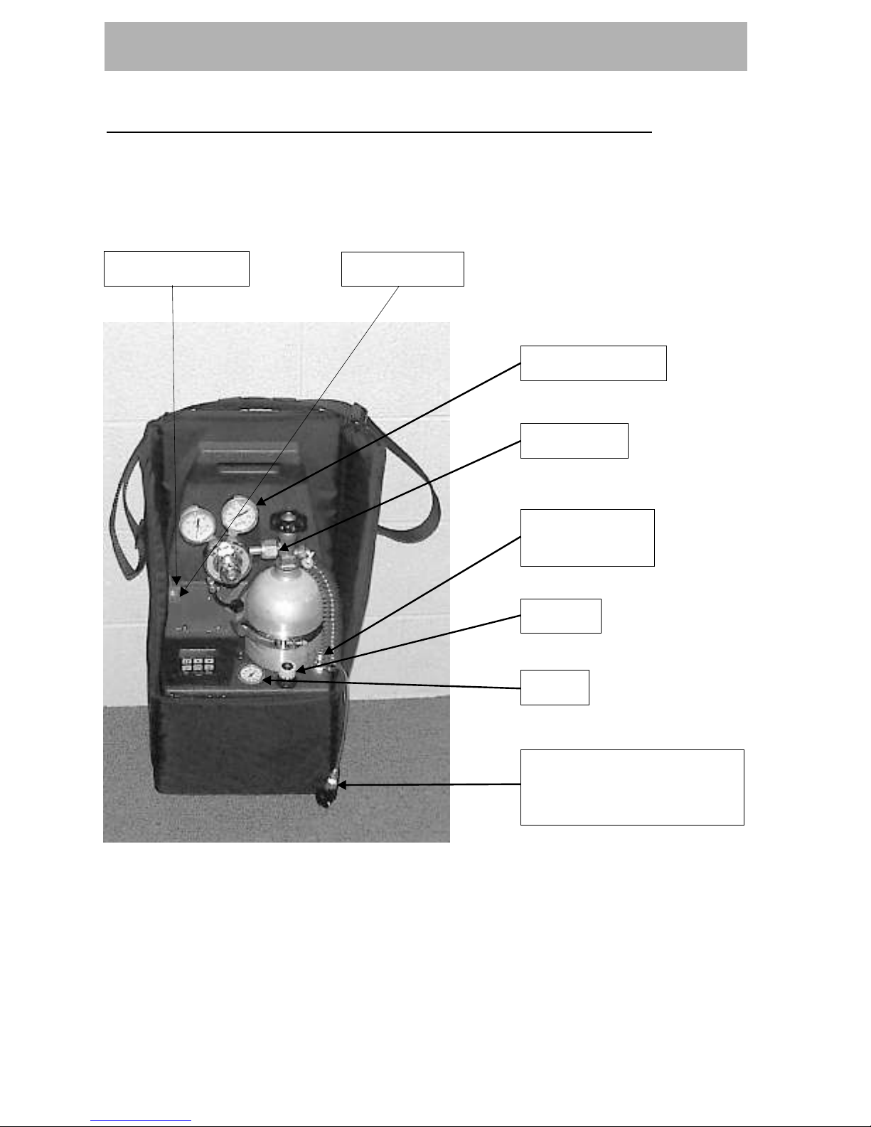
Introduction: The MP15 Micro Purge Basics Controller is used to
operate QED Well Wizard bladder sampling pumps to purge and sample
ground water. The MP15, with its self-contained CO2 cylinder (or
another compressed gas source connected to the bypass supply fitting)
is taken portably from well to well. The MP15 has specific design fea-
TM
tures to make MicroPurge sampling easier. These features include:
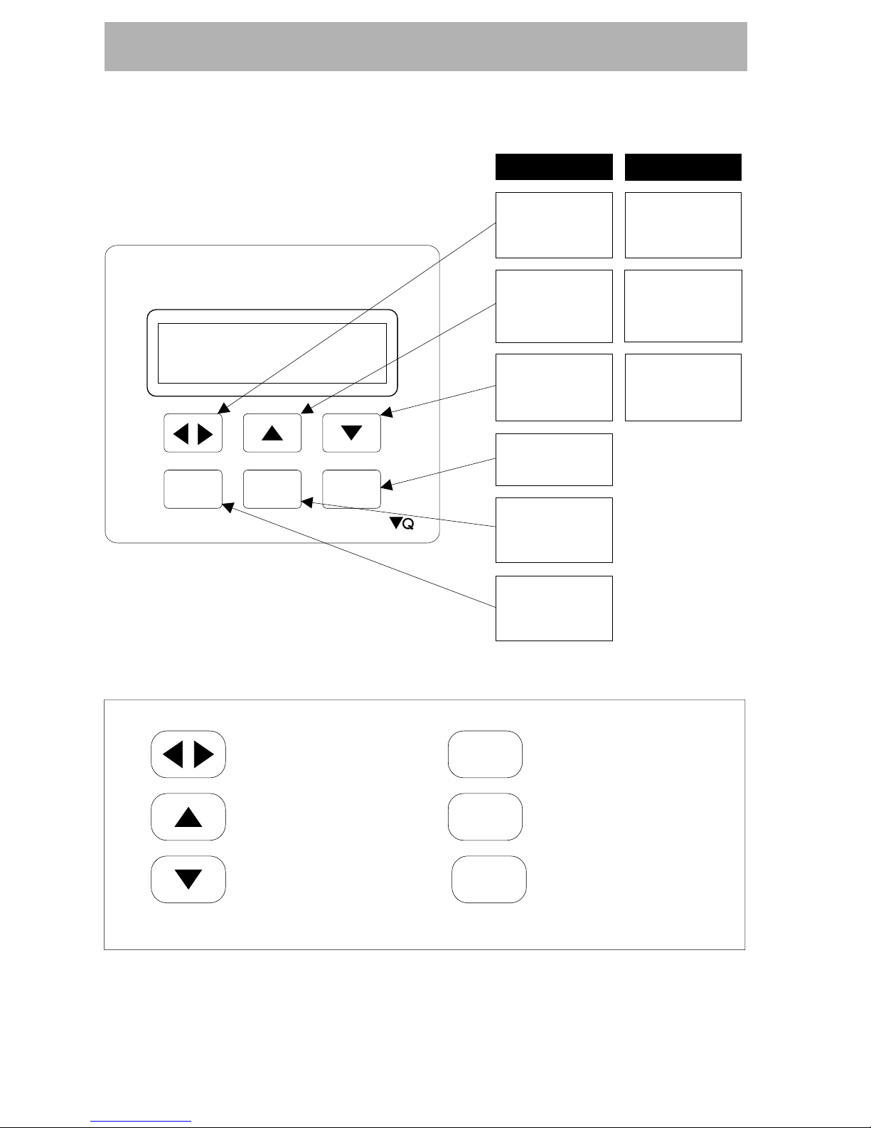
MicroPurge Mode Operation Simple Increase / Decrease keys
allow you to easily set the flow rate you need for each well.
ID Time Set Mode Operation Quickly recalls pre-determined set-
tings for each well by specifying a 3-digit ID.
Level Delay Interface The controller plugs into the optional MP30
MicroPurge Drawdown / Water Level Meter to provide direct feed-
back of well drawdown and to pause pump operation until the level
recovers.
The optional MP30 MicroPurge Drawdown / Water Level Meter plugs
into the MP15 to provide water level feedback. The MP30 uses a stan-
dard conductivity probe to detect the ground water surface and a marked
tape allowing the user to measure the depth. When the meter is set in
MicroPurge mode, the probe is lowered a specific distance below the
static water level and fixed in this position. During well sampling if the
water level drops below the user-set probe position, the MP15 is paused
which prevents further drawdown by the pump. Once the level recovers
the MP15 begins pump operation again, starting in the pump refill cycle.
Use of the MP15 with the MP30 is detailed later in this manual.
Insert Batteries: Remove the battery cover on the top of the MP15.
Insert 3, AA alkaline batteries into the battery holder and carefully rep-
lace the holder in the carrier. Replace the battery cover and tighten the
4 screws. Batteries should last for about 6-8 weeks of typical full-time
field use. If the MP15 will be stored longer than 3 months, the alkaline
batteries should be removed to prevent leakage.

INTRODUCTION/QUICK START
Quick Start: Open the CO valve and supply up to 125 psi compressed
air or gas to the controller. Turn the controller throttle until the gauge
reads the approximate depth of the sample pump. Follow instructions on
the battery panel:
Move Red ON/OFF toggle switch up to turn power ON.
Select desired Cycles Per Minute (CPM) with (default value is 4
CPM, lower CPM for deeper wells, higher CPM possible with shallow
wells).
Turn throttle to set depth on gauge to 10-20 feet deeper than the pump
location in the well.
Cycle
I I
Press to START pumping.
When water discharge begins, adjust throttle until a slow, steady flow-
stream is achieved.
Press keys to set the desired purge flow rate.
To collect samples, continue purge flow, or use key to directly
control sample flow and pause.
8
CO Regulator2
Gasket Inside
Connector Nut
CO Tank Nut2
2

9
Operation
Turning the MP15 Display On - The MP15 is powered on by moving
the Red ON/OFF toggle switch (located above the control port) up to
the ON position. When the Red power toggle switch is moved upward
the MP15 displays an opening screen for 5 seconds, after which it dis-
plays the default MicroPurge screen. At this point the MP15 is in
MicroPurge mode (MP) but not cycling the pump. This initial state
allows the user to adjust time and throttle settings before the pump starts
to operate. Pressing the Cycle key begins pump cycling. Times and
modes may be adjusted while the pump is cycling or before. Pressing the
Cycle key a second time will stop pump cycling. Note: All user-entered
time settings are lost when the MP15 is turned off. Also, the MP15 does
not automatically power down so make sure the Red power toggle is
turned Off (down position) during storage.
Opening Display - The opening display is shown for 5 seconds and
displays the controller name, the version number and the battery voltage,
as shown in Figure 1. Figure 1 shows that the battery is GOOD, that the
battery voltage is 4.20 volts and that the software version in the cont-
roller is 1.0. Battery voltage must be greater than 3.6 volts for the unit
to operate. If the unit fails to cycle replace the 3-AA batteries with fresh
cells. The opening screen is displayed for 5 seconds, if you wish to by
pass the opening screen, hitting any key, such as the CPM key will bring
you to the default MP display.
Figure 1 Opening Screen
OPERATION
MicroPurge Basics Controller
MP Micro Purge
ID ID Time Set MN Manual Time Set
LVL LevelShutoff
CYCLE
I I
MODE
CPM/Value Flow/Value Flow/Value
Hold/Sample
/Cycle
Start/Stop ID/MN/MP/
Battery
Mode CPM
ID
Time Refill
Discharge
QED
MP15
V1.0
BAT GOOD 4.20
DD
EE

MicroPurge Mode Most MP15 users will leave the controller in the
default MicroPurge (MP) mode. See Figure 2 for an example of the
MP15 in MP mode. MP mode lets you to use the UP and DOWN keys
to directly increase and decrease pump flow rates. The MP15 has a
broad range of other CPM settings to ensure the availability of a time
setting that will match your specific conditions. ( MP mode also disp-
lays an ID, with a value of 1 to 165 that matches the flow settings
(CPM ) and refill and discharge times you have set). This ID should be
noted alongside the well identification (QED provides custom weather-
proof ID badges for purchasers of our MP series of well caps) for quick
setting of the optimal controller settings on the next visit by using the
MP15 in ID mode.
Figure 2 MP15 MicroPurge Mode
Using CPM The MP15 introduces a revolutionary, simpler way to con-
trol bladder pump flow rate and achieve the low-flow method used by
experts. Up/down arrow keys are used to adjust pump flow even at very
low rates, with excellent control and repeatability.
.
10
OPERATION
With previous bladder pump controllers, a leading low-flow technique
called for selecting the number of pump cycles per minute, then adjust-
ing the bladder pump discharge and refill times to achieve the desired
volume per cycle. These adjustments were inter-related, complex, and
varied by operator. The new MicroPurge Mode (MP) of the MP15
builds in a "cycles per minute", or CPM, method of flow control.
MicroPurge Basics Controller
MP Micro Purge
ID ID Time Set MN Manual Time Set
LVL LevelShutoff
CYCLE
I I
MODE
CPM/Value Flow/Value Flow/Value
Hold/Sample
/Cycle
Start/Stop ID/MN/MP/
Battery
Mode CPM
ID
Time Refill
Discharge
00.1
103
10.0
MP CPM4 >05.0
DD
EE

With this method, the number of complete pump cycles per minute is
fixed, within a range of 1 to 6; 4 CPM is the default value which ap-
pears at startup. Each time the up/down arrow keys are pressed, the
pump refill and discharge times are both automatically adjusted to
maintain the selected CPM value. Each adjustment increases or de-
creases the volume pumped per cycle, and the per-minute flow rate is
the volume per cycle X the CPM value.
OPERATION
11
For example, with a 4 CPM setting, 60 ml volume per cycle equates to
4 X 60 = 240 ml/min flow rate. A single press of the Flow up-arrow
key could change the volume per cycle to 80 ml, for example, resulting
in a new, increased flow rate of 4 X 80 = 320 ml/min. And the MP15
assigns a unique identification value to each setting, the ID value, which
can be directly set during later sampling events.
"MP" displayed in the lower left corner of the display indicates Micro-
Purge mode. The default CPM setting of 4 cycles per minute is a good
starting point for wells with depths from 25-100ft. MicroPurge mode
starts at a time setting of 10 seconds refill and 5 seconds discharge,
close to optimal for many wells. This startup settings corresponds to a
4 cycles per minute setting (CPM4) and an ID setting of 103.
Using the CPM key will change the CPM setting on the controller. The
range of CPM settings is CPM1 through CPM6. CPM changes like this
each time you hit the CPM key: 4 5 6 1 2 3 4 5, etc. The UP and
DOWN keys change the flow rate directly, by altering the refill and dis-
charge times within a CPM setting. Note: changes in settings that are
entered while the controller is cycling are reflected on the next cycle
change (so a long refill time of 15 seconds will time out before a new
refill time becomes valid).
Here is an example of the use of the UP (faster) key:
Refill Discharge ID
(sec) (sec)
Key Press
---
1
2
3
10.0
9.5
9.0
8.5
5.0
5.5
6.0
6.5
103
104
105
106

OPERATION
Each of the 165 possible ID settings corresponds to a unique ID that is
associated with CPM, refill and discharge time values. For typical us-
age, only the UP/DOWN arrow keys are required to set flow, and the ID
number is provided for easy, direct return to past settings. Appendix 1
lists all possible ID settings and the default refill and discharge time
settings for each CPM. Appendix 1 also shows how the refill and dis-
charge time will change within a CPM setting as you press the UP or
DOWN keys.
12
Sample Collection The PAUSE key ( ) is used to freeze the
controller action to allow the user time to collect a sample or carry out
other steps that might be difficult if the controller continued to auto-
matically cycle and cause the pump to produce water. While the cont-
roller is cycling, pressing the PAUSE key causes the controller to imm-
ediately enter the Hold state. Drive air is vented from the pump (this is
the pump refill cycle) and the pump fills and waits. Pressing the PAUSE
key a second time causes the controller to immediately enter the Sample
state. Drive air is directed to the pump causing the pump to discharge
its volume of liquid. Bladder pumps typically hold 400-500ml of liquid,
so use of the Hold and Sample states allow the full volume of the pump
to be discharged into a sample container. Pressing PAUSE once again
returns the MP15 to its normal Automatic Cycling state. During Hold
and Sample a HELD is displayed to remind you that the controller is in
a paused state. Figure 3 shows an example of the MP15 in MP mode,
but HELD in the Sample state. Note: Pressing the Cycle key also freezes
controller cycling. However, using the Cycle key rather than the Pause
key causes the startup screen to be displayed upon restart. Use of the
Pause key is recommended for typical operation.
I I
Figure 3 MP15 Held State (MP mode)
MicroPurge Basics Controller
MP Micro Purge
ID ID Time Set MN Manual Time Set
LVL LevelShutoff
CYCLE
I I
MODE
CPM/Value Flow/Value Flow/Value
Hold/Sample
/Cycle
Start/Stop ID/MN/MP/
Battery
Mode CPM
ID
Time Refill
Discharge
HELD
103
10.0
MP CPM4 >05.0
DD
EE

OPERATION
Warning: in the HELD SAMPLE state the pump, tubing and hoses are
all under pressure. DO NOT attempt to disconnect or disassemble any
part of the system when it is under pressure. The system is under pres-
sure if the pressure gauge shows a value greater than 0 and the RED
Discharge Cycle Indicator is showing.
Flow Throttle Use The flow throttle is used during sampling to regu-
late the pressure applied to the pump. Turning the throttle clockwise in-
creases the pressure and counterclockwise decreases the pressure. The
pressure gauge shows the approximate pressure applied to the pump
and reads in units of Feet-H O. This allows easy adjustment of the
2
throttle giving pressures that will produce gentle, non-turbulent flow
(normally 10-20 Feet- H O deeper than pump depth). For traditional,
2
high volume purging pressure may be increased with the throttle to
maximize pump flow during well purging.
Use with the MP30 Automatic Drawdown Control The MP15 may
optionally be used with the MP30 MicroPurge Drawdown / Water Level
Meter. See Figure 4 for an example of the MP15 in MP mode with the
controller in a level paused state enacted by an MP30 meter.
Figure 4 MP15 Level Paused State (MP mode)
13
MicroPurge Basics Controller
MP Micro Purge
ID ID Time Set MN Manual Time Set
LVL LevelShutoff
CYCLE
I I
MODE
CPM/Value Flow/Value Flow/Value
Hold/Sample
/Cycle
Start/Stop ID/MN/MP/
Battery
Mode CPM
ID
Time Refill
Discharge
LVL
10.0
MP CPM4 >05.0
DD
EE

OPERATION
Figure 5 MP15 MP30 Use
Figure 6 MP15 MP30 Use
14
MP30 Drawdown
Meter
MP15 MP30
Maximum Point
of Drawdown
Normal
Static
Level
MicroPurge Basics Controller
MP Micro Purge
ID ID Time Set MN Manual Time Set
LVL LevelShutoff
CYCLE
I I
MODE
CPM/Value Flow/Value Flow/Value
Hold/Sample
/Cycle
Start/Stop ID/MN/MP/
Battery
Mode CPM
ID
Time Refill
Discharge
00.1
103
10.0
MP CPM4 >05.0
DD
EE
CONTROLLER
MP15
MicroPurge Mode Quick Guide
3 AA BATTERIES INSIDE
MODEL
1. Turn power switch ON.
2. Select desired Cycles Per Minute (CPM) with
the key (default value is 4 CPM).
3. Turn throttle to set depth on gauge to 10-20
feet deeper than the pump location in the well.
4. Press CYCLE to START pumping.
5. When water discharge begins, adjust throttle
until a slow, steady flowstream is achieved.
6. Press keys to set the desired purge
flow rate..
7. Use key to directly control sample flow
and pause.
II
O
U
EEDD
asics
OFF
ON
ON/OFF (Red) Toggle Switch
Control Port

15
OPERATION
The MP15 and MP30 are connected with a cable (see Figures 5 and 6).
The MP30 is switched into "DRAWDOWN CONTROL" mode and the water
level probe is lowered to the desired maximum drawdown level. Limit-
ing the maximum drawdown depth limits the differential head driving
flow into the well and the velocity of the water flowing into the well
from the surrounding formation important in MicroPurge sampling.
The MP15 and MP30 work together to automatically adjust the pump
operation so as to maintain drawdown at the set level. When the water
level drops below the probe, the MP30 sends a signal to the MP15 to
pause pumping. Both the MP15 and the MP30 give visual signals (and
the MP30 emits an audio signal) that pump operation has stopped be-
cause of too much drawdown. Once the level recovers, the MP30 sig-
nals the MP10 to resume pump operation. The MP15 resumes by start-
ing in the refill leg of the pump cycle.
The normal operating mode for using the MP30 with the MP15 is:
1. Use the MP30 in standard WLM mode to determine the static water
level in the well
2. Decide what the maximum drawdown for that well is during samp-
ling
3. Lower the probe to the maximum drawdown level
4. Switch the MP30 into Drawdown Control mode
5. Begin pumping with the MP15
6. Observe the interactions between the two devices, if the MP30 is fre-
quently pausing the MP15, it may be appropriate to slow the flow
down (using the DOWN key in MP mode) to better match pump flow
to well recharge.
When switched into "DRAWDOWN CONTROL" mode, the MP30 has a
flashing red light and an optional (can be switched off by the user)
audio alarm to indicate when the probe is in the dry state. A submerged
probe in all modes is indicated by a solid green light. When the MP15
is paused by the MP30 the MP15 display indicates this as shown in
Figure 4.

OPERATION
Figure 7 MP15 ID Set Mode
16
MicroPurge Basics Controller
MP Micro Purge
ID ID Time Set MN Manual Time Set
LVL LevelShutoff
CYCLE
I I
MODE
CPM/Value Flow/Value Flow/Value
Hold/Sample
/Cycle
Start/Stop ID/MN/MP/
Battery
Mode CPM
ID
Time Refill
Discharge
00.1
103
10.0
MP CPM4 >05.0
DD
EE
If the MP30 is signaling the MP15 too frequently, the operator can slow
down the pump flow rate by using the DOWN key (effectively increas-
ing the pump refill time period). MP30 probe position may also be
varied to provide a buffer zone for your draw-down limit and gauge
rate of pumping effect on water level in the well.
If the selected maximum drawdown level is being reached even with
the lowest desirable pump flow rate more drawdown may be required
to attain equilibration, or a passive sampling approach may be required.
In passive sampling, used where well recovery is extremely slow, sam-
ples are taken after just a few pump strokes sufficient to purge the pump
and tubing volumes.
Additional information on the MP30 is given in the MP30 O&M
manual
ID Mode Figure 6 shows an example of the MP15 in ID time set mode.
Once you use the MP10 in MP mode and found proper settings for your
wells, subsequent sampling events are speeded along by using the con-
troller in ID mode. Once the controller is turned on, a single press of
the MODE key places the controller in ID time set mode (the default
initial mode is MP mode). This mode allows the user to enter a 3-digit
ID, which then is translated into the correct flow settings (CPM and
refill / discharge time settings) for that well.

OPERATION
Figure 8 MP15 User Set Mode (MN mode)
17
MicroPurge Basics Controller
MP Micro Purge
ID ID Time Set MN Manual Time Set
LVL LevelShutoff
CYCLE
I I
MODE
CPM/Value Flow/Value Flow/Value
Hold/Sample
/Cycle
Start/Stop ID/MN/MP/
Battery
Mode CPM
ID
Time Refill
Discharge
00.1
10.0
MN >05.0
DD
EE
In this mode the CPM and UP, DOWN keys function differently. The
CPM key becomes a key used to scroll between the one's and the ten's
digits of the ID. The UP and DOWN keys are used to change the ID
number (the MP15 has IDs that range from 1-165) up or down in value.
Sampling in ID mode is the same as explained, above, for MP mode.
Appendix 1 lists all possible ID settings and the default refill and dis-
charge time settings for each CPM. Appendix 1 also shows how the re-
fill and discharge time will change within a CPM setting as you press
the UP or DOWN keys. As you change IDs you will see the CPM
change and the refill and discharge time setting change. Note: changes
in time settings that are entered while the controller is cycling are ref-
lected on the next cycle change (so a long refill time of 15 seconds will
time out before a new refill time becomes valid).
User Set Mode A final controller mode, User Set mode (MN on the
display), is useful for manually setting refill and discharge times on the
controller as in traditional controllers (like previous model QED pump
controllers). An example of the MP15 in User Set mode is shown in
Figure 7. User set mode is also used when the wells being sampled are
at extreme depths or there are other conditions where one of the 165
possible preset times of ID and MP modes will not match your needs.
MN mode is entered when the MODE key is pressed twice from the
default MP mode. As shown in Figure 7, the display indicates MN
mode in the lower left corner and CPM and ID are not displayed.
Table of contents