National Luna DC40 User manual

Power Pack DC40

1
Index
3
3
4
5
6
7
8
9
9
10
10
11
12
14
17
15
Changing Battery Type
Connecting External Battery Chargers
Introduction
Connecting DC power sources
Ignition Over-ride
Safety Information
Features
Wiring Diagram
Preparing for Installation
Installing Battery
Connecting Solar Panels
Remote Monitor
Remote Monitor Status Messages
Specifications
Warranty
System Operation

2

Introduction
3
ŸEnsure the Power Pack DC40 is secured in mobile applications.
ŸDo not alter or modify the Power Pack DC40 under any circumstances.
ŸDo not attempt to charge a non-rechargeable or battery other than 12V.
ŸUnauthorized disassembly, repairs or modifications will void any warranty.
ŸNever attempt to charge a damaged or leaking battery.
ŸThe Power Pack DC40 is used for charging 12V lead-acid and automotive Lithium batteries only.
ŸDo not use for any purpose other than indicated in this manual.
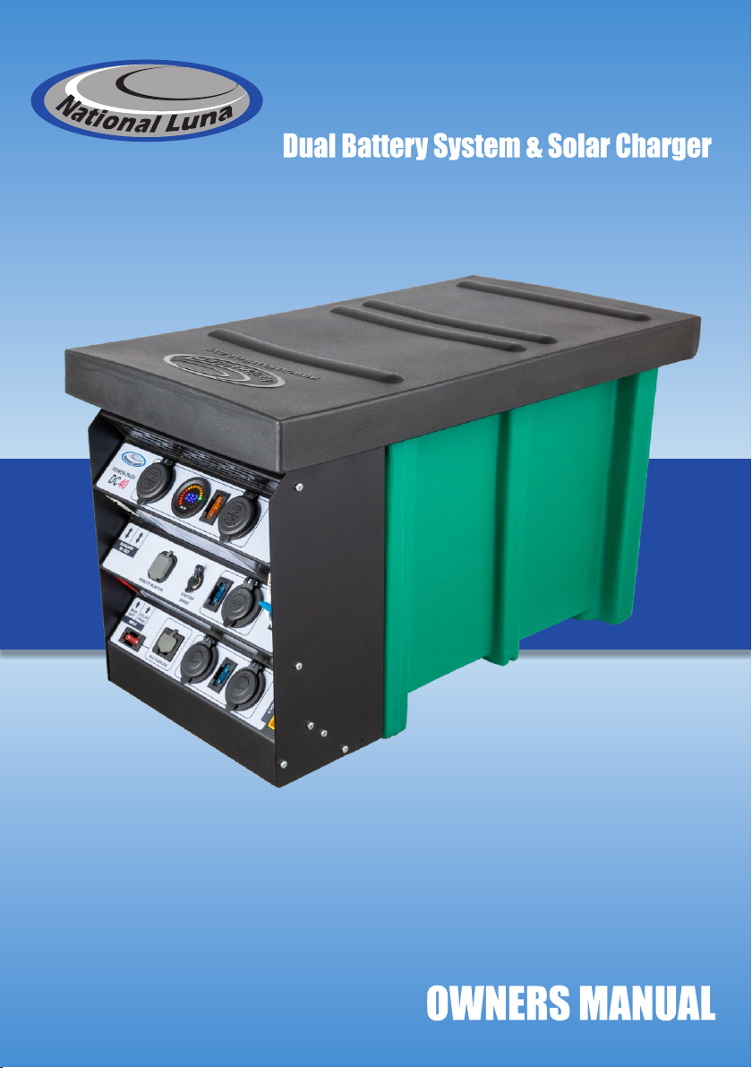
ŸDisconnect any existing batteries.
ŸEnsure all connections are secure and cables are installed in a safe manner.
ŸAvoid open flames in the vicinity of the battery.
ŸInstall the supplied in-line fuse as indicated in the installation instructions.
ŸAttempts to use the Power Pack DC40 for purposes other than indicated in this manual will void the
warranty.
ŸBefore installation, read the instructions carefully.
ŸUse the correct cabling size and fuses in accordance with the installation instructions.
This combination results in a self-contained split-charge system that is at-home in the vehicle or in camp
and can be used to power fridges, lights, pumps and other 12V appliances.
The Power Pack DC40 can be charged from a vehicle alternator, solar panels or external chargers making
it versatile for a variety of applications.
The Power Pack DC40 supports 12V lead-acid (wet, calcium, Gel, AGM) as well as lithium batteries.
Two dual-port USB modules with fast charge allows several smart devices such as smart-phones, tablets,
GPS, cameras and other USB-devices to be powered up to 18W on each port.
to fridges and other small appliances. These connectors can also be used with external battery chargers
as an alternative to the built-in dedicated charge port.
The National Luna Power Pack DC40 blends the convenience of a portable battery system and the
performance of a DC-DC battery charger with MPPT solar regulator.
The primary charge input supports 12V and 24V vehicle systems and will provide up to 40A of current to
the auxiliary battery using an optimized 6-stage charge algorithm.
Heavy-duty connectors can be used for connecting a variety of accessories from inverters (600W max)
A built-in 40A MPPT solar regulator circuit supports solar panels up to 42V and provides up to 40A (600W)
charge current to the battery.
Supported battery types (set to AGM by default) :
ŸLithium-ion, LiFePO4
Temperature Compensation & battery protection :
ŸLead-acid (Calcium, Flooded, AGM, Gel, VRLA)
ŸThe battery charge profile takes into account battery temperature with a sensor (located inside the
battery compartment) for safe charging under various conditions.
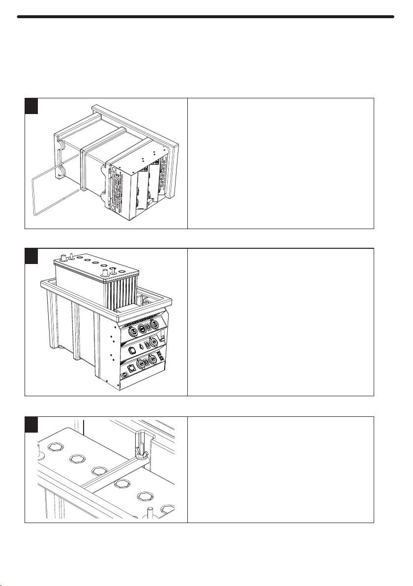
Max battery size :
Ÿ330mm x 180mm x 280mm (L x W x H)
SAFETY INFORMATION :

Features
4
USB Charge Modules
Battery Gauge
Main Switch
50A Heavy-duty
IN/OUT connectors
SOLAR PANEL input
Remote Monitor port
IGNITION sense port
MAIN BATT input
External Charger input
Charger input fuse
Hella-type DC Socket
Direct DC Input
12V DC Sockets
Fuses
Control Panel
Sliding Lid
Battery Compartment

5
Wiring diagram - Typical Installation
NOTICE - Importance of correct cable type and connection quality.
To vehicle
MAIN battery
DC source
11V - 32V
Fuse
Fuse
SOLAR Panels
SOLAR
MAIN
BATT
DC IN
50A
+
+
-
-
The Power Pack DC40 input current can be expected to reach 50A under normal conditions.
Poor connections result in high voltage loss, lowering system performance.
Follow these guidelines during installation :
Special care must be taken to ensure that the cable, connectors and power source are rated for this
current.
- If more than one system is installed, avoid the use of shared cabling.
2
- A cable thickness of 16mm (5 AWG) is recommended.
- Ensure all cable terminals are crimped with appropriate tools.
- Use the correct size of terminal and ensure they are clean and free of corrosion.
- Always use the supplied fuses or replace with the same type and value of fuse.

MAIN
BATT
SOLAR
PANEL
INPUT
If a standard solar panel is used, it can be connected to the input marked "SOLAR PANEL".
Before installing a battery into the Power Pack DC40, select the correct battery type.
(Instructions on page 7)
Make sure all connections are secure and terminated correctly with appropriate tools.
For applications where the Power Pack DC40 is installed in a vehicle, locate the Power Pack such that
the input cables are not restricted or under strain. The Power Pack should also be secured to prevent
movement.
The input cables must be terminated with a RED 50A coupler matching the input on the Power Pack
DC40 marked "MAIN BATT".
Once the battery type is selected, a battery can be installed into the Power Pack DC40 and the RED
input cable connected (Fig 2).
2
Use 16mm cables for the input from the vehicle main battery and install the supplied 50A in-line fuse
close to the main battery on the positive cable (Fig 1).
Connect the supply from the main
battery (alternator) to the RED input
on the Power Pack DC40.
Ensure terminals are crimped securely.
Install the fuse on the positive cable
close to the main battery.
Fig 1 Fig 2
6
Preparing for Installation

Changing battery type
7
This is best done before the battery is inserted into the Power Pack DC40.
For safety, the battery type cannot be changed if the auxiliary battery is already connected.
The battery type should be chosen before the auxiliary battery is installed.
A power source can be connected to the MAIN BATT, SOLAR PANEL or DC INPUT to power the system
and change the battery type.
Wet
AGM / Gel
Ca+
Li-ion Used for automotive Lithium-ion or
LiFePO4 batteries.
Used for regular automotive starting
and flooded high-cycle batteries.
Used for flooded deep-cycle, calcium
and maintenance-free batteries.
Used for all types of AGM and Gel
batteries.
Left side Right side
1
34
2
The cover can now hinge open.
Remove screws from the left, right and bottom as indicated.
The cover can now be opened fully to expose the
internal DC-DC system.
With the cover slightly open, unplug the remote
monitor cable.
Connect power to the MAIN BATT or SOLAR input.
The DC-DC system will now activate and show the
current battery selection.
Remove the cover of the internal DC-DC system by
loosening two screws on top.
- The auxiliary battery can now be installed.
Once the preferred battery type is selected, disconnect
the power source.
- Replace the cover of the DC-DC system.
- Re-connect the remote monitor plug and close the cover.
- Re-install the screws that were removed earlier.
Battery Types
5
6
The AGM battery type
is the default factory
setting.
To change this, press
the "Battery" button
until the desired type is
highlighted.
DC-DC Battery Charger
Battery
Float
Li-ion Wet
Ca+ AGM/Gel
Charge
OK /

8
Installing Battery
It is best to lay the Power Pack on its side or end to do this.
To hold a battery securely in the Power Pack, install the U-bolt and hold-down bracket.
Note : Select the battery type before installing the auxiliary battery. See page 7.
Return the Power Pack to the
upright position.
Insert the U-bolt through the holes
drilled into the bottom of the
Power Pack.
Remove the Power Pack sliding lid
and insert the auxiliary battery into
the battery compartment.
Attach the hold-down bracket,
washers and wing-nuts.
Connect the positive (RED) and
negative (BLACK) cables to the
battery terminals.
Make sure the connections are
clean and tight
Take care not to over-tighten the
screws.
1
2
3

9
Connecting Solar Panels
Connecting additional DC power sources
Fuses for DC power sources
The Power Pack supports the direct connection of
solar panels up to 42V through the heavy-duty connector
marked "SOLAR PANEL".
Note that if the solar panels have internal or in-line
regulators, connect them to one of the AUXILIARY
IN/OUT connectors instead.
To utilise the full 40A output capability of the Power Pack
DC40, the DC source should have a rating of 600W or
more with a voltage between 11V and 32V.
* Do not connect battery chargers to this input.
The DC input on the Power Pack DC40 is designed as
an alternative input that can be used with DC power
sources such as AC-DC power supplies, wind turbines,
hydro-electric and generators with DC output.
The fuse current rating should be more than the maximum expected source current but not more than
50A.
When using an external DC power source, install a fuse close to the power source on the positive cable.
DC Power Supply
11V - 32V +
-
FUSE
DC IN
DC INPUT

10
Ignition over-ride (optional accessory)
CAUTION
Insert the charger quick-connector into the charge port
labeled "NL5 CHARGER" until it clicks securely.
This port can support up to 10A charge current.
The Power Pack has a charge port specifically for use
with National Luna Intelligent Battery Chargers.
Make sure the main breaker switch is in the ON position
during charge.
In order to connect other brands of chargers to this input,
a quick-connector cable is available separately.
Larger-power inverters should be connected directly to
the battery terminals.
When using chargers or inverters connected to the
AUXILIARY IN/OUT plugs, the main switch must be ON.
In order to use higher-power battery chargers with
currents greater than 10A or other brands of chargers, it
is recommended to connect to one of the AUXILIARY
IN/OUT plugs. These plugs have a 50A continuous
rating.
AC Inverters can be connected to the AUXILIARY
IN/OUT plugs for powers up to 600W.
Plug the larger end into a socket that provides a positive
voltage only when the ignition of the vehicle is ON.
The IGNITION SENSE port allows the Power Pack to support
vehicles where the charge voltage drops very low or is very
erratic.
This may be the case in some vehicles with "Smart
Alternators".
Plug the small end of the over-ride cable into the
IGNITION SENSE port.
Only use the IGNITION SENSE feature if the vehicle alternator voltage is below 13.2V under normal
conditions.
Connecting the IGNITION over-ride to a permanent 12V source may result in excessive discharge of
the MAIN battery.
IGNITION
SENSE
NL5 CHARGER
Connecting external Battery Chargers
High-current Chargers and Inverters

System operation
11
If the Power Pack DC40 is not in use then it is best to turn this
switch OFF. This will completely isolate the auxiliary battery.
In order to charge or supply power to accessories connected to any
of the plugs & sockets, the main switch on the Power Pack DC40
must be in the ON position.
Charger fuse
If any of the fuses need replacement, be sure to
replace it with the correct value :
Bottom group
Middle group
Each of the modules and sockets are grouped
with a fuse for safety.
The groups are surrounded by a line on each of
the levels of the control panel.
Top group
Fuses
Main Isolator Switch
Multiple charge input sources can be connected simultaneously. The Power Pack DC40 will give priority to
the MAIN BATT source first then SOLAR and then DC input. Switching between these sources will be
automatic.
If the IGNITION SENSE input is used, the Power Pack DC40 will charge with input voltage above 12.0V
and stop when voltage drops below 11.5V. (MAIN BATT input)
The Power Pack DC40 will start to charge the auxiliary battery once voltage on the MAIN BATT input
exceeds 13.2V or a valid voltage is provided on the SOLAR or DC inputs.
It will stop charge once voltage drops below 12.6V after a short delay.
If a solar panel is connected and exposed to sunlight, the Power Pack DC40 will charge with the maximum
power possible from the panel under the present conditions. Voltage from the panel must be between 9V
and 42V.
Top group
(5A)
Middle group
(15A)
Bottom group
(15A)
Charger fuse
(10A)
NL5 CHARGER
MAIN
BATT
SOLAR
PANEL
INPUT
5A
15A
15A
10A
:
:
:
:
POWER PACK
DC 40
DC INPUT
REMOTE MONITOR
IGNITION
SENSE
AUXILIARY
IN / OUT

Remote Monitor - (Optional accessory)
12
Connecting the Remote Monitor
Information such as Main and Auxiliary battery voltages,
charge mode, charge current, battery type, battery
temperature and error conditions are displayed in a
choice of 3 user-selectable display modes.
In addition to the selectable screen modes, the user is
able to increase or decrease the screen brightness and
choose to turn the display on or off.
The screen will turn off automatically when the system
is idle. It will turn on automatically when the next charge
cycle starts.
on a high-contrast LCD screen.
The Remote Monitor can be plugged into the Power
Pack DC40 and provides status about the system
It can fit in one direction only.
This connector can fit both ways.
Connect the flat end of the data cable to the Remote
Monitor. (fig 2).
Locate the Remote Monitor in a convenient location
using the supplied mounting fixture.
Press the plug until it clicks securely.
Connect the square end of the supplied data cable to
the Power Pack remote port as indicated (fig 1).
Lift the dirt cover on the Remote Monitor port.
Fig 2
Power
Screen mode
Brightness UP
Brightness DOWN
Fig 1
REMOTE MONITOR

Remote monitor operation
13
If SOLAR or DC is the active charge source, the displayed voltage
represents the voltage of that source.
Display mode 1 - This mode focuses on the auxiliary battery with the
majority of the screen used to show the auxiliary battery voltage and
If there are no active charge cycles, “STBY” is displayed.
The input source (ALT, SOLAR or DC) as well as charge current is
displayed during a charge cycle.
battery temperature.
The display will turn off automatically after a short delay if there is no active charge cycle.
The remote monitor can be turned ON or OFF by pressing the POWER button.
The display brightness can be increased or decreased by pressing the UP or DOWN buttons.
If there is no active charge cycle, “STANDBY” is displayed.
During a charge cycle, the input source (ALT, SOLAR or DC) is displayed
with the actual charge current.
Display mode 2 - In this mode, the status of the main and auxiliary
batteries are represented as graphical bar-graphs.
The actual voltages are shown for the respective batteries.
If there are no active charge cycles, “STBY” is displayed.
Display mode 3 - This mode shows voltages of the respective main and
auxiliary batteries as well as charger mode, charge current, battery type
and battery temperature.
The remote monitor has 3 display modes that represent the status of the charging system in different
ways.
Press the MODE button to cycle through the different display options.

Remote monitor STATUS messages
14
The following symbols or messages may appear on any of the 3 display modes :
The remote monitor will respond and indicate various error conditions that may occur under normal
operation. These warnings should be investigated to prevent damage to the batteries or the Power Pack.
The remote monitor will show the charge status during an active charge cycle.
During the normal bulk and absorption charge stage, the charge current will be shown as well as the
input source.
During the Analysis stage, “TEST” will be shown. This stage helps to detect a defective battery.
During the Float stage, “FLOAT” is shown.
Warning Messages
Ensure the applied voltages are within specification. Refer to specifications on page 15.
Charge will stop until the system temperature recovers to a safe level.
This error will also be displayed if the Power Pack internal circuit temperature is above 115°C.
If this symbol and voltage display are flashing, the battery is not holding charge and should be
tested.
Check fuses and connections to both batteries. Ensure the main switch is ON when in use.
REVERSE POLARITY - The connections to the auxiliary battery have been reversed.
OVER TEMPERATURE PROTECTION - The detected auxiliary battery temperature is above 60°C.
Charging is stopped to prevent damage to the battery.
LOW BATTERY or NO BATTERY - This symbol is displayed when either the Main or Auxiliary battery
voltage is lower than 11.4V or there is no connection to one of the batteries.
OVER VOLTAGE PROTECTION - The voltage applied to the SOLAR or ALT inputs is too high.
BAD BATTERY - The Power Pack has detected that the AUX battery is not able to be charged safely.
Test the battery and replace if necessary.
OVER CURRENT PROTECTION - The detected charge current is higher than specification.
Inspect the installation for cable faults or short-circuits.
Check the battery connections.
OVP -
OTP -
OCP -
REV -
BAD -
Please check cable The plug to the remote monitor may not be inserted correctly. Ensure it is fully inserted.

Specifications
15
Charge Algorithm
Voltage
Diagnosis Recovery Bulk Absorption Analysis Float
Current
Step 1 2 3 4 5 6
Battery Temperature Compensation
High temperature
Low temperature
Battery temperature protection
Device Protection
Reverse Polarity
Over Voltage
Over Current
Bad Battery Detect
-17mV per °C above 30°C
+17mV per °C below 21°C
60°C
Over Temperature
Battery Types Bulk Voltage Float Voltage
AGM / Gel 14.4V 13.6V
Standard Wet 14.6V 13.6V
Calcium 14.8V 13.6V
Lithium Ion / LiFePO4 14.4V 13.6V
USB charge output (each port) 5V-3A, 9V-2A, 12V-1.5A
Input Voltage Range
MAIN BATT / DC inputs
SOLAR PANEL Input
Input priority
Solar Regulator
DC Input
Type
Voltage range
Rated Current
Turn OFF
Rated Power
Over- Voltage
12V Alternator Input
Turn ON
Turn OFF
Over-Voltage
24V Alternator Input
Turn ON
Turn OFF
Over-Voltage
Ignition Over-ride (12V / 24V)
Turn ON
Turn OFF
Over-Voltage
Output
Voltage
Current
Power
Operating Temperature
Standby Current (switch ON)
Dimensions
Remote Display
9V - 42V
MAIN - SOLAR - DC
11V - 32V
13.2V
12.6V
MPPT
11V - 32V
600W
32V
40A
< 11V
14.8V - 16V
-20°C to 85°C
11.5V 23V
15.5V - 16V 31V - 32V
3V -14.8V
40A
600W
<50mA
26.4V
23.2V
29.6V - 31V
12.0V 24V
Optional
498mm x 280mm x 306mm
Battery Gauge display range 10.7V - 14.7V

16
Maximum Battery Size
280 mm
145 mm
306 mm
330 mm
290 mm
460 mm
180 mm
498 mm 280 mm
- - - mm

17
National Luna warrants this product to be free from defects in materials and / or workmanship under normal use and
service to the original purchaser subject to the following :
This National Luna Warranty supersedes any other advertised Guarantee or Warranty provided with this appliance by
any wholesaler or retailer.
1. At any time within THREE YEARS from the date of purchase by the original purchaser, National Luna will at its
discretion replace or repair without cost to the owner, through an authorised service agent, any part found to be
defective by National Luna.
2. Where parts are replaced by an authorised service agent, the labour costs for the work done will be for the owner’s
account.
3. This warranty does not apply to accessories or items where the length of life depends on the amount of use and care
this appliance.
6. National Luna shall not be responsible for any damages of any kind resulting from incorrect voltages or faults with
given.
malfunctioning of this appliance.
9. National Luna will not accept any responsibility for the consequential loss or damage caused by, or due to the
12. National Luna reserves the right to refuse repair or service under warranty if the original proof of purchase cannot be
13. Removal of serial numbers may render the warranty void.
10. National Luna shall not be held responsible for any injuries to persons caused by the incorrect or negligent usage of
4. This warranty is valid in South Africa only.
8. Warranty returns to the factory for repairs - in the event where the unit has been shipped to the factory for repairs,
produced.
5. National Luna may consider a warranty void if modifications have been made to this product which may cause
7. National Luna shall not be responsible for damage to the product caused by negligent use, storage of hazardous
transport costs will be for the owners account.
any work is performed.
undesirable or hazardous operation or may be the cause of the malfunction of this product.
chemicals, use of corrosive substances, fire, flood, civil-disturbances, lightning or any other natural phenomenon.
11. Repair work to be done in terms of this warranty must be referred to National Luna for written authorisation before
regards to power supply which fall outside of the appliance operating specifications.
National Luna Limited Warranty - South Africa Only

National Luna Limited Warranty - International
country other than South Africa.
(at their cost) in line with the various countries’ conditions of sale.
2. Cross-border customs and duties apply. A National Luna manufactured product that is returned to the factory in South
1. National Luna has a world wide distributor network. These distributors import products and carry the warranty
Africa will have the South African warranty applied. However, all transport costs incurred will be for the purchaser’s
account.
Any labour and parts required for repairs would incur costs in foreign currency and be for the owner’s account.
The standard National Luna Warranty in South Africa cannot be applied outside the South African borders for practical
reasons.
3. It is important to note that a private purchase of this product in South Africa and exported will not carry a warranty.
4. In the event of a National Luna product being fitted as standard equipment in caravans and trailers and subsequently
being exported from South Africa, the warranty must be carried by the persons responsible for the importing into a
5. It is recommended that National Luna products be purchased from the authorised importer in a particular country who
carries the applicable warranty and back-up service.
18

19
Replaceable Modules
The lower group can accommodate the following 29mm
modules :
The Power Pack DC40 is designed to allow some of the
plugs & sockets to be replaced with other compatible
modules within the 29mm range.
Replacing modules requires that the Power Pack DC40 cover be
removed and the wiring be manipulated.
This should only be done by qualified persons.
Dual USB charger
(Engel plug compatible)
Screw-in DC socket
Hella-type socket
Cigarette-lighter socket
(factory fitted)
12V DC socket
(factory fitted)
CAUTION
Table of contents
Other National Luna Power Pack manuals