MicroAir Avionics T2000ADSB User manual

T2000ADSB TRANSPONDER
USER MANUAL
Microair Avionics Pty Ltd
ACN 646 664 459
601 Curtin Ave East
Pinkenba QLD 4008
Australia
Phone: +61 7 4160 8200
Email: support@microair.aero
sales@microair.aero
Web: www.microair.aero

T2000ADSB Transponder
User Manual
T2000ADSB User Manual 01R2
Page 2 of 24
24th March 2023
About This Document
Microair Avionics has developed the T2000ADSB transponder to provide for aircraft surveillance requirements of ATCRBS
Mode 3A/C with ADS-B.
This is a controlled document, and may not be copied, amended, or distributed without the prior consent of Microair Avionics Pty
Ltd.
© Microair Avionics Pty Ltd
DOCUMENT REVISION STATUS
Revision
Date
Change
1R1
6/02/23
Initial Draft
1R2
24/03/23
Minor corrections, Programming section moved to Installation Manual.

T2000ADSB Transponder
User Manual
T2000ADSB User Manual 01R2
Page 3 of 24
24th March 2023
TABLE OF CONTENTS
1.0 INTRODUCTION.............................................................................................4
1.1 ATCRBS CODES.....................................................................................................................4
1.2 MODE 3A/C .............................................................................................................................5
1.3 MODE ADSB ...........................................................................................................................6
2.0 T2000ADSB DISPLAY.....................................................................................7
2.1 LAYOUT ..................................................................................................................................7
2.2 DISPLAY FUNCTION.............................................................................................................8
3.0 CONTROL FUNCTIONS ................................................................................9
3.1 SELECTMODE KNOB............................................................................................................9
3.2 CODE SELECT KNOB..........................................................................................................10
3.3 INFORMATION SELECT KEY............................................................................................11
3.3.1 PA - PRESSURE ALTITUDE............................................................................................................................ 11
3.3.2 UT - TIME UTC................................................................................................................................................. 11
3.3.3 TR - TRACK. ..................................................................................................................................................... 12
3.3.4 X - LATITUDE (WHERE X = N OR S)............................................................................................................. 12
3.3.5 X - LONGITUDE (WHERE X = E OR W)........................................................................................................ 12
3.3.6 GA - GPS ALTITUDE. ...................................................................................................................................... 12
3.4 MODE KEY............................................................................................................................13
3.4.1 ASSIGNED (ALTITUDE).................................................................................................................................. 14
3.4.2 QNH (BAROMETRIC PRESSURE).................................................................................................................. 15
3.4.3 BACKLIGHTING .............................................................................................................................................. 16
3.4.4 FLIGHT ID......................................................................................................................................................... 16
3.4.5 BUFFER ALT..................................................................................................................................................... 17
3.5 ENTER KEY...........................................................................................................................18
3.6 TOGGLE KEY .......................................................................................................................18
3.7 VFR –HOT KEY ...................................................................................................................19
3.8 ID KEY...................................................................................................................................19
4.0 ERROR MESSAGES......................................................................................20
5.0 FREQUENTLY ASKED QUESTIONS:.......................................................21
6.0 LIMITED WARRANTY ................................................................................23

T2000ADSB Transponder
User Manual
T2000ADSB User Manual 01R2
Page 4 of 24
24th March 2023
1.0 INTRODUCTION
The T2000ADSB has been designed to operate seamlessly in two different modes, to satisfy aircraft surveillance
requirements:
➢ATCRBS Mode 3A/C
➢ADS-B
Both mode of operation will operate simultaneously. ADS-B operates at all time power is applied and the data
required for a message is available. ATCRBS operates when the aircraft is airborne.
The ADS-B messages are derived from an inbuilt GPS source. The T2000ADSB also has an inbuilt altimeter but is
designed to operate with any TSO-c88a compliant altimeter or encoder, depending on user preference.
1.1 ATCRBS Codes
Aircraft operating in controlled airspace will be allocatged a unique 4 digit code. Aircraft operating outside but in
close proximity to controlled airspace may be allocated a code but would generally squawk that countries VFR code
(1200 in most countries).
There are also several special codes, which are used to identify aircraft in special situations. These include:
1200
Civil VFR Flights OCTA not participating in Radar
Information Service (RIS). General Aviation Code (US and
other countries)
7000
VFR General Aviation Code (Europe)
7500
Unlawful Interference Code
7600
Radio Communications Failure
7700
Emergency Code
IMPORTANT NOTE
ALWAYS check the standby code, BEFORE transferring it to the ACTIVE
position.
Code 2100 is a test code that can be used by qualified personnel to test the transponder to ATC.
The user should check the Civil Aviation Rules/Regulations to determine the VFR General Aviation transponder
code for their country.
The ADS-B message includes information, which describes the aircraft’s “status”. The aircraft’s status is determined
by the currently selected mode A ID code.
Example: Code 7500 is selected Aircraft status = UNLAWFUL INTERFERENCE
Code 7600 is selected Aircraft status = NO COMMUNICATION
Code 7700 is selected Aircraft status = EMERGENCY
For all other mode A codes the aircraft status will be NO EMERGENCY.
T2000ADSB Transponder
User Manual
T2000ADSB User Manual 01R2
Page 5 of 24
24th March 2023
1.2 Mode 3A/C
The Microair T2000ADSB Transponder is compliant to RTCA/DO-144, and will operate in the environment of a
Radar Beacon System. This system interrogates the transponder, which in turn replies with identity code and altitude
information. The radar system consists of a network of ground stations, which sweep the horizon like conventional
radar. When the transponder in the aircraft detects the radar sweep (is illuminated), the transponder replies with a
burst transmission giving its identity code and altitude.
The system presents the replies from all transponders in range of the ground stations on a single display screen. This
allows ATC to easily locate, identify, and see the altitude of all traffic in their airspace.
A transponder’s reply is termed a squawk. Hence the current code being used by the transponder is termed the
squawk code. At times of high airspace activity, ATC may wish to uniquely identify an individual aircraft with a
request to squawk ident. When the pilot uses the ident control on the transponder, a distinctive indication appears on
the ATC display. The ident control should not be used unless ATC requests it.
ATC will issue a code to an aircraft requesting entry into its controlled airspace. This code is normally unique for
each aircraft, each time that aircraft passes through the airspace. The code is 4 digits long, and each digit can range
from 0-7.
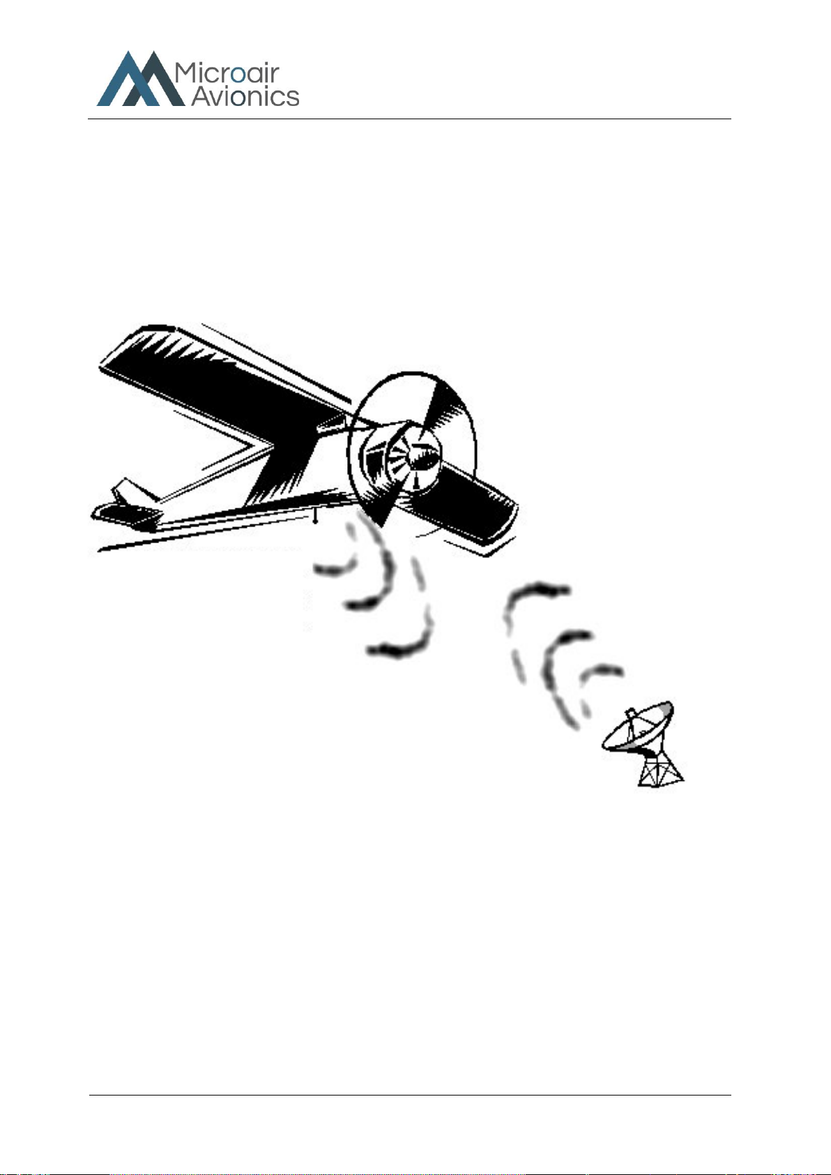
The aircraft’s transponder
receives the ground station
signal asking it to transmit. The
transponder “replies” with the
code, and if operating in mode
C, the encoder altitude.
Ground stations sweep the sky with a signal, which
asks the transponder in the aircraft to transmit its
code and altitude.

T2000ADSB Transponder
User Manual
T2000ADSB User Manual 01R2
Page 6 of 24
24th March 2023
1.3 Mode ADSB
The Microair T200ADSB is compliant with RTCA/DO-260, and will transmit ADSB squitter messages
containing the aircraft’s position (from and GPS source), identity, altitude, and status (eg normal, no comm.,
emergency, etc).
The feature which makes ADS-B transponders different to Mode A/C or Mode S types is they are not
dependent on radar to interrogate them. The ADS-B transponder will issue a series messages called extended
squitters. These messages are sent at a rate of approximately 6 messages per second. The position information
in these messages is sourced from a compliant GPS receiver that in addition to position and velocity also
provides integrity. Integrity is a measure of the quality of the satellite data available to the receiver in that
location at that time. The GPS receiver must be capable of calculating the integrity as a value to be sent in the
squitter message. If the integrity falls below a certain level the position data cannot be used by ATC.
Other aircraft may be equipped with ADS-B receivers (ADSB in), which can receiver and decode ADS-B
extended squitter messages. This information can then be displayed in the cockpit to give the crew an accurate
indication of the traffic situation around them.
The ADS-B message data for the aircraft status is linked to the mode A code. If the pilot selects a mode A
code to indicate an abnormal situation (eg 7600 = No Communications), the aircraft status data will change to
reflect this.
Aircraft emits a squitter
messages giving ID,
position, altitude, and
status several times per
second
Some aircraft are also equipped to
receiver ADS-B squitter
messages. This information can be
display in the cockpit to show the
position of other traffic
ATC receives all ADS-B
squitter messages, which are
then displayed to controllers
T2000ADSB Transponder
User Manual
T2000ADSB User Manual 01R2
Page 7 of 24
24th March 2023
2.0 T2000ADSB DISPLAY
2.1 Layout
The Microair T2000ADSB is a 57mm diameter face version to fit the standard 2 ¼ inch instrument hole. The
mounting is by 4 x M4 machine screws, located through the panel and screwed into threaded holes in each corner of
the transponder’s front face.
IMPORTANT NOTE
Use only the factory supplied screws or M4 x 12mm machine screws. Do
NOT oversize the holes, or use over-length screws. These actions may
damage internal components of the transponder.
Microair T2000ADSB SFL
Refer to the T2000ADSB Installation manual for full details on how to install your transponder.
T2000ADSB Transponder
User Manual
T2000ADSB User Manual 01R2
Page 8 of 24
24th March 2023
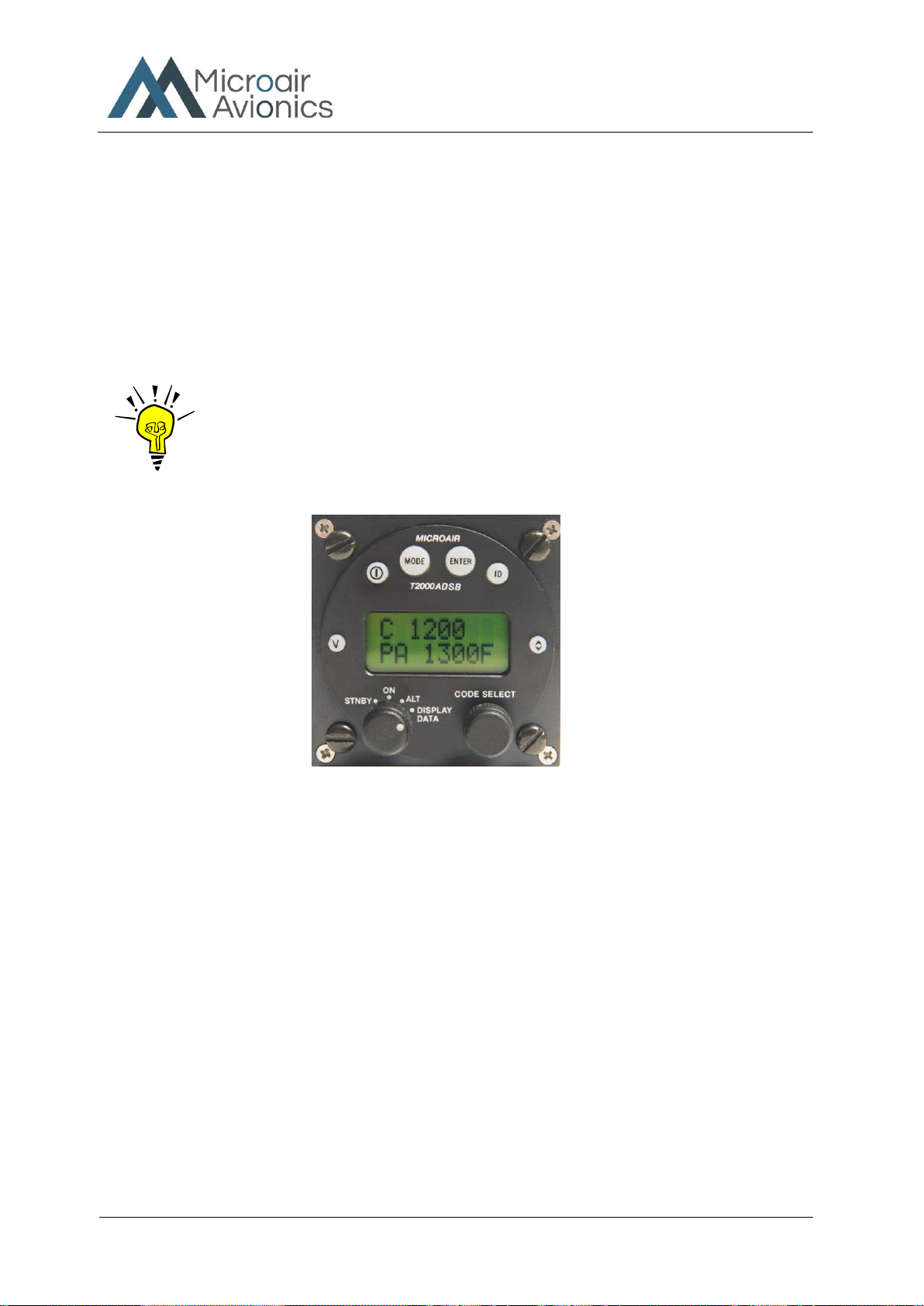
2.2 Display Function
The T2000ADSB has a dual line display of 8 characters each, with the active code on the top line, and the standby
code on the bottom. With the SELECTMODE knob set to either the ON or ALT positions, the active code is
displayed on the top line, and the standby code is displayed on the bottom line.
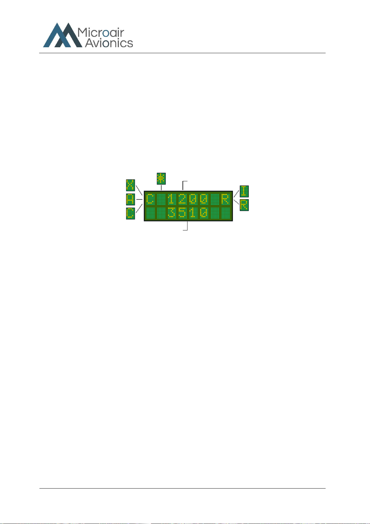
In the top left corner the operational mode character (X, A, or Ccharacter) is displayed. Next to it is the ADS-B
annunciator (*character) which remains on when the ADS-B squitter has transmitted. At the top right is the Mode
A/C annunciator (Rcharacter) which flashes with every transponder reply transmitted. If the ID key is pressed to
activate the ident function, the R character is replaced with an I character while the ident function is operating.
With the SELECTMODE knob in the ALT DISPLAY position, the active code is displayed on the top line, and
the various position, velocity and time (PVT) information is displayed on the bottom line. Refer section 3.3 below.
Standby Code
Never Transmitted
X - STANDBY
Neither code or altitude are sent
A - MODE 3A
Transmit ON –Only ID code sent
C - MODE C
Transmit ON –ID Code and altitude sent
Icharacter
Squawk Ident operation
Rcharacter (flashing)
Mode A/C annunicater
Active Code
The transmitted ID code
* character ADSB annunciator

T2000ADSB Transponder
User Manual
T2000ADSB User Manual 01R2
Page 9 of 24
24th March 2023
3.0 CONTROL FUNCTIONS
This section describes the transponder control keys and their functions. Many of the control keys have more than
one function, and some keys access multi-option menus, which can be scrolled.
3.1 SELECTMODE KNOB
The SELECTMODE knob allows the user to switch the
transponder between the 4 operating modes.
STANDBY
In standby the transponder is powered up, but will not transmit in any mode A/C replies. ADSB is
active.
On the active display line the letter X appears on the left hand side.
ON
The T2000ADSB will reply to Mode Ainterrogations with the active ID code displayed on the top
line. The T2000ADSB will also reply to mode Cinterrogations, sending framing pulses only, in
accordance with mode 3requirements.
On the active display line the letter Aappears on the left hand side.
ALT
Will reply to Mode Aand Cinterrogations, with the mode Cencoder information. In the absence of a
valid encoder input, only the Cframing pulse will be sent.
On the active display line the letter Cappears on the left hand side.
ALT DISPLAY
The standby code is replaced with the data display option selected by pressing the (I) info button.
On the active display line the letter Cappears on the left hand side.
CONTROL
DESCRIPTION
1
INFO SELECT Key
2
MODE Key
3
ENTER Key
4
IDENT Key
5
TOGGLE Key
6
CODE SELECT Knob
7
SELECTMODE Knob
8
VFR Key
Selectmode Knob
T2000ADSB Transponder
User Manual
T2000ADSB User Manual 01R2
Page 10 of 24
24th March 2023
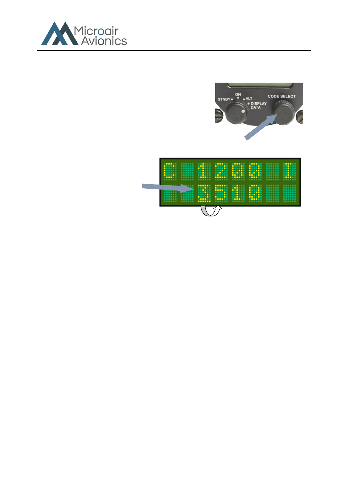
3.2 CODE SELECT Knob
The CODE SELECT knob can be rotated clockwise to scroll
upwards, and counter-clockwise to scroll downwards. Each digit of
the code is adjusted separately. The adjust function starts with the left
hand digit, and is moved across to the next digit by pushing the
CODE SELECT knob inwards. After 10 seconds of inactivity the
cursor will revert to the left hand digit.
Press the CODE SELECT knob inwards to move the
cursor to the next digit.
Code Select
To increase the digit value, rotate the
CODE SELECT knob clockwise. To
reduce the digit value, rotate anticlockwise.
Only values from 0-7 can be selected.

T2000ADSB Transponder
User Manual
T2000ADSB User Manual 01R2
Page 11 of 24
24th March 2023
3.3 INFORMATION SELECT KEY
The Information Select key is used to cycle through a number of
different T2000ADSB information screens as shown below. Note
that the Information Select button only displays data when the
Code Select Knob is turned to the ALT DISPLAY setting.
3.3.1 PA - PRESSURE ALTITUDE
Pressure Altitude (altitude with reference to 1013Mb) OR Q - Altitude with reference to the set QNH in
either Feet or Meters
If the altitude units are set to feet the altitude is followed by the F character. If the altitude units are in metres,
the altitude is followed by the M character. If no QNH or BARO value has been entered (default 1013mB or
29.92HG), the raw encoder output is displayed as “pressure altitude”, and the characters PA appear at the
lower left. If a QNH / BARO value has been set, the Q character appears at the lower left.
3.3.2 UT - TIME UTC
Displays UTC time. LT (Local Time) is functionality that will arrive soon.
Info Select Key
PA Pressure Altitude as sent
from the altitude encoder.
FFeet
Altitude units are in Feet
QAltitude is adjusted for
QNH or barometric pressure
from the mode menu
Displayed Altitude
Altitude generated by Encoder, and may be
adjusted for barometric pressure (QNH)

T2000ADSB Transponder
User Manual
T2000ADSB User Manual 01R2
Page 12 of 24
24th March 2023
3.3.3 TR - TRACK.
This screen shows the GPS derived true track and GPS derived ground speed in KTS.
3.3.4 X - LATITUDE (WHERE X = N OR S).
This screen shows the GPS derived latitude as DD.DDD i.e. S27.3250 or N54.2814
3.3.5 X - LONGITUDE (WHERE X = E OR W).
This screen shows the GPS derived longitude DDD.DDD i.e. E153.083 or W007.125
3.3.6 GA - GPS ALTITUDE.
GPS Altitude is derived as the Height above WGS-84 ellipsoid.

T2000ADSB Transponder
User Manual
T2000ADSB User Manual 01R2
Page 13 of 24
24th March 2023
3.4 MODE KEY
Press the MODE key to access the MODE MENU. The
first item of the MODE MENU is displayed. Step
through the MODE MENU by pressing the MODE key.
After the last menu item the T2000ADSB returns to the
operational display currently in use
The MODE MENU is designed to allow the operator fast easy access to functions and parameters, which may need
to be adjusted in flight.
MODE MENU
Assigned Altitude
QNH
Backlighting
Flight ID
Buffer Altitude
back to Operational Mode
Mode Key
USE MODE KEY TO STEP
THROUGH OPTIONS
OR
USE THE Toggle KEY TO
RETURN TO THE
OPERATIONAL DISPLAY

T2000ADSB Transponder
User Manual
T2000ADSB User Manual 01R2
Page 14 of 24
24th March 2023
3.4.1 ASSIGNED (ALTITUDE)
The user can input an assigned altitude given by ATC. When used with
the altitude buffer value, an audio alert and display indicator advises
when the aircraft has climbed or descended, from the assigned altitude.
Press MODE key (1 time)
To select Assigned option
Press CODE SELECT knob
Change increment display value between thousands of feet and
hundreds of feet
Rotate CODE SELECT knob
Increment displayed value.
Press ENTER key
To set default value. The default is 0.
Press ENTER or toggle key
To save and display returns to current operational display
When entering an altitude…
Press the CODE SELECT knob to Change increment display value
between thousands of feet and hundreds of feet.
Rotate the CODE SELECT knob to increase or decrease the height
value.
Press the ENTER key to return the ASSIGNED ALTITUDE to the default value of 0,
OR
Press the Toggle key to save the height value, and return to the operational display.
If Assigned is set to 0, the altitude alert function is disabled. The assigned altitude function is only active when the
SELECTMODE knob is set to DISP ALT.
T2000ADSB Transponder
User Manual
T2000ADSB User Manual 01R2
Page 15 of 24
24th March 2023
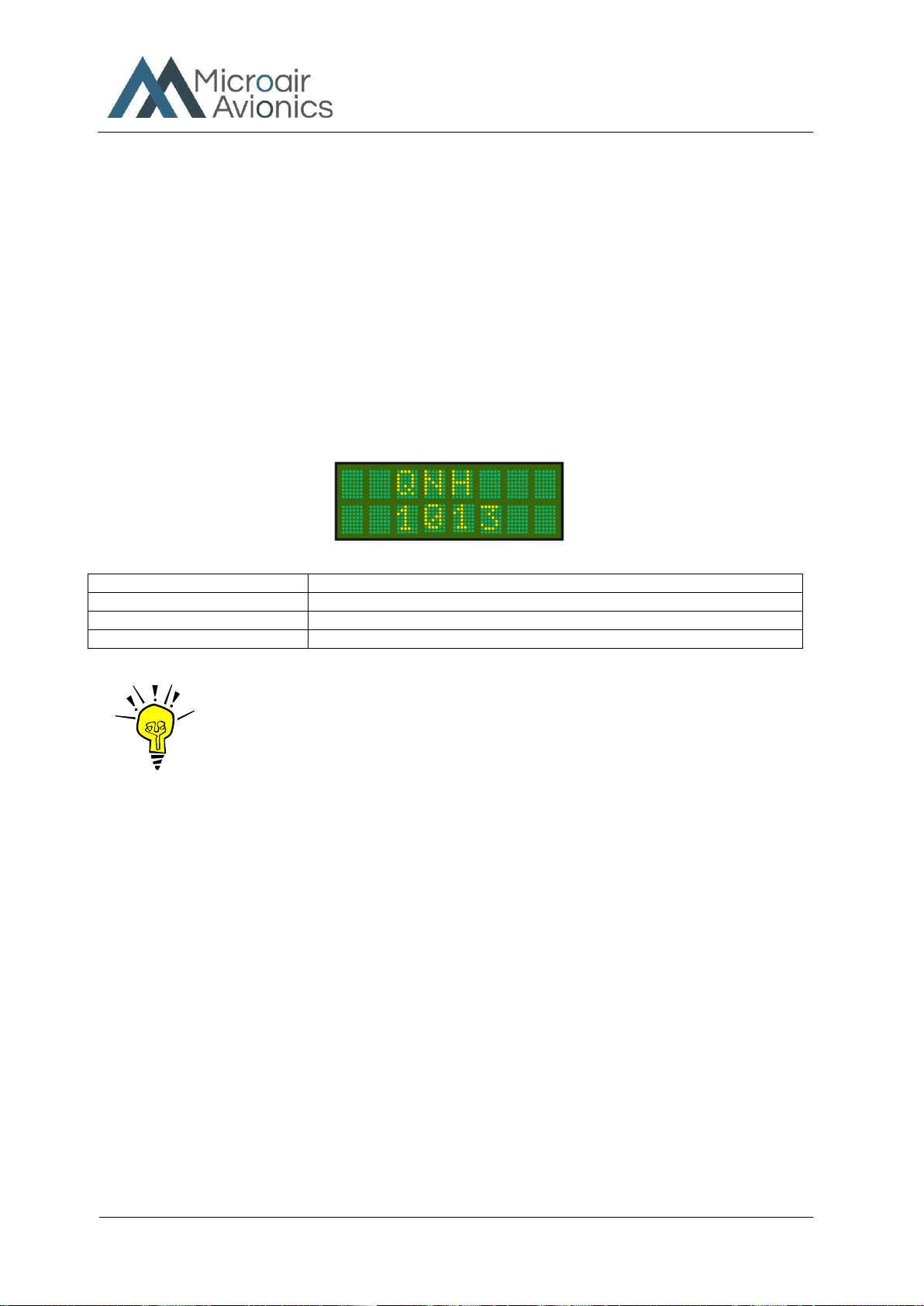
3.4.2 QNH (BAROMETRIC PRESSURE)
The altitude encoder outputs a pressure altitude relative to a fixed pressure of 1013mb (29.92inHg) and this is the
altitude always reported in the Mode C reply and ADS-B extended squitter messages. The aircraft’s altimeter
however is normally adjusted for actual surface pressure before take off and during flight. This means the encoder
altitude may not be the same as the altimeter reading.
The QNH can be entered here to allow the T2000ADSB to compensate the displayed altitude for surface pressure,
and hence read the same as the aircraft’s altimeter. The default QNH is 1013mb (or 29.92 if inHg selected, see
programming mode below). If the QNH is set to 1013mb, the altitude displayed will default to the unadjusted
pressure altitude direct from the encoder. If the QNH is set to a discrete value (normally provided by ATC), the
displayed encoder pressure altitude will be adjusted for the QNH value. The pilot can select any barometric
pressure over the range 900 –1100mB (or 27.00 - 31.99inHg).
Press MODE key (once)
To select QNH option
Rotate CODE SELECT knob
Scroll QNH value up or down to the desired value. The default is 1013
Press ENTER key
To set default value.
Press toggle key
Display returns to current operational display
IMPORTANT NOTE
The T2000ADSB will only transmit the encoder pressure altitude. The
adjusted QNH altitude is NEVER transmitted, even when it is selected
for display.
T2000ADSB Transponder
User Manual
T2000ADSB User Manual 01R2
Page 16 of 24
24th March 2023
3.4.3 BACKLIGHTING
The T2000ADSB LCD display backlight has 11 levels available from 0 –100%. The level set is remembered and
set once the self test is completed during the net power up. Off to its brightest level:
Press MODE key (5 times)
To select BACKLITE option
Rotate CODE SELECT knob
Rotate the code select clockwise to increase the backlight brightness (up to
100%) and counter clockwise to decrease the brightness (down to 0%) in
10% increments.
Press toggle key
Setting is saved & the display returns to current operational display
For battery operators, Microair Avionics recommends that the backlighting be set off to save power.
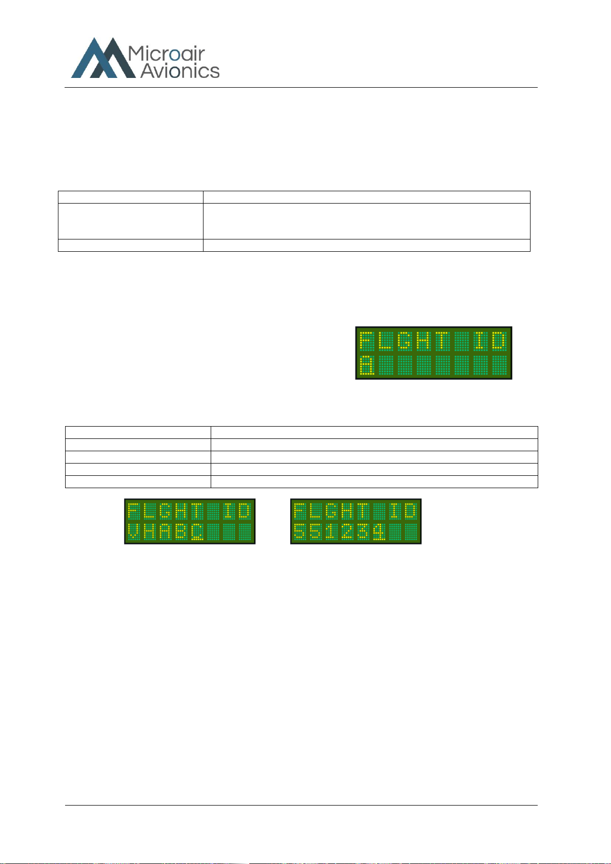
3.4.4 FLIGHT ID
For most sport and general aviation aircraft the Flight ID will be
the aircraft’s registration or call sign and is not likely to be
changed. Once the flight ID is inputted, it is saved into memory,
and will be recalled when the transponder is next turned on. The
Flight ID defaults to the A/C ID from the PROGRAM MODE
menu.
If the Flight ID is not entered, the ADS-B message will transmit “null” values in the Aircraft Identification message.
Press MODE key (6 times)
To select FLT ID option
Rotate CODE SELECT knob
Scroll lower line to select desired character. The default ID is the aircraft ID.
Press CODE SELECT knob
Moves cursor to the next character.
Press ENTER key
To set default value. Default value is blank.
Press toggle key
Display returns to current operational display
There are rules governing the correct makeup of the flight ID, to ensure the ADS-B message is formatted correctly.
In most cases the flight ID will be the aircraft’s registration. The default value of the flight ID is the aircraft ID that
is inputted in the PROGRAM MODE menu
The flight ID can have a maximum of 8 characters and can consists of capital letters A-Z and the numbers 0-9 with
spaces in the trailing unused positions (spaces are not allowed in within the Flight or Aircraft IDs.

T2000ADSB Transponder
User Manual
T2000ADSB User Manual 01R2
Page 17 of 24
24th March 2023
3.4.5 BUFFER ALT
The user can input a buffer altitude, above and below the assigned
altitude, to define a height band in which to fly. When the aircraft
exceeds the upper or lower limit, an indicator alert message will be
displayed. The alert message advises the pilot of how far, above or
below the assigned altitude the aircraft is. If audio output is connected to
the aircrafts audio system, an audio tone is heard as well.
Press MODE key (3 times)
To select Buffer Alt option
Rotate CODE SELECT knob
Select the buffer altitude in 50' increments in the range 0 to 2000'
Press ENTER key
Save and move to the next item
Press Toggle key
Save and Display returns to current operational display
If the aircraft climbs or descends outside the altitude buffer limits, a Hi / Lo warning is displayed on the lower line.
With the Assigned altitude set at 3500 feet, and the
Buffer Alt set at 200 feet, the display alerts will
occur over 3700 feet and under 3300 feet.
The alert tone is heard as the aircraft passes out of the
buffer zone.
No alert will be displayed while the aircraft remains
inside the 3700-3300 buffer.
ASSIGNED ALTITUDE
ALTITUDE BUFFER
ALTITUDE BUFFER
T2000ADSB advises the pilot that the aircraft is 500 feet
above the Assigned altitude. An audio warning tone is
heard.
T2000ADSB advises the pilot that the aircraft is 500 feet
below the Assigned altitude. An audio warning tone is
heard.

T2000ADSB Transponder
User Manual
T2000ADSB User Manual 01R2
Page 18 of 24
24th March 2023
3.5 ENTER KEY
The ENTER key is a confirmation key used to confirm information the user has inputted. After pressing the
ENTER key, the display will typically give the message SAVED,for a short period.
The ENTER key is also used to quick-set a parameter to a default value.
The ENTER key is also used to acknowledge alerts and error messages. When an alert or error message appears on
the lower line of the display, the pilot can press the ENTER key to acknowledge the alert / message. The display
will then revert to the previous operational display.
Some alerts or error messages, if the alert or error situation continues, will after a preset time display again on the
lower line, to remind the pilot that the alert / error still exists.
3.6 TOGGLE KEY
This key acts as a toggle switch, exchanging the active and standby codes.
When the transponder is operating in ALT DISPLAY the bottom line displays the
encoder altitude instead of the standby code. The standby code is stored in memory.
To toggle the active and standby codes in this mode, push the toggle key once to
display the standby code on the bottom line. The standby code is displayed for 10
seconds. Push the toggle key again to exchange the active and standby codes. Once
the codes have been exchanged, the display will revert back after 10 seconds, to
displaying the altitude on the bottom line.
In all modes of operation, only the active code is transmitted.
The toggle key is also used to return to the operational screen from the MODE and PROGRAM MODE menus.
Enter Key
Toggle Key
T2000ADSB Transponder
User Manual
T2000ADSB User Manual 01R2
Page 19 of 24
24th March 2023
3.7 VFR –HOT KEY
To bring the stored VFR code to the standby line press the ENTER key then the VFR
key.
The VFR key will default the standby code immediately to the stored VFR code.
Typically this code will be 1200 for a General Aviation aircraft. The VFR key calls the
value set in the VFR option of the PROGRAM MODE menu.
To transfer the VFR code to the active position, press the toggle key. If no code is
entered, after 10 seconds idle the standby position will revert back to the original VFR
code.
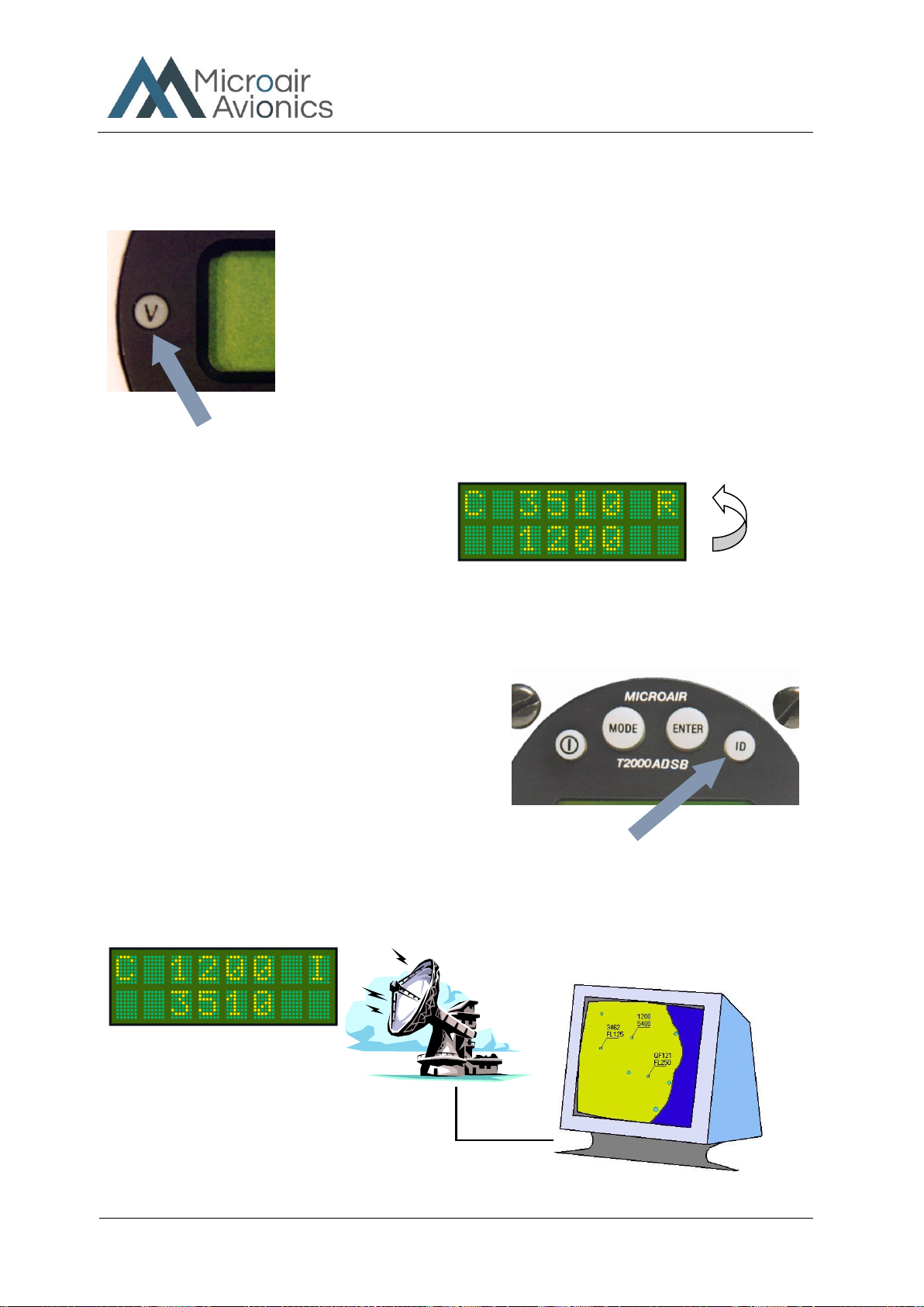
3.8 ID KEY
To initiate the Ident function press the ENTER key then the ID
key. The ident function will operate for approx 18 seconds.
The ID key (Ident) when pressed, adds additional code
information to the transmission for ATC. The code will flash
on the ATC display as a means of uniquely identifying the
aircraft’s code from any other.
The ID key only needs to be pressed briefly to activate the ident function.
Ident data is also added to the ADS-B message to ensure that the ident function is transmitted in all modes.
.
VFR Key
Ident Key
I character replaces the R, while the
IDENT function is in operation
Press VFR key to bring the stored
VFR code to the standby line. In this
case VFR = 1200
To make the VFR code the
active code, press the toggle key
to bring VFR to the top line

T2000ADSB Transponder
User Manual
T2000ADSB User Manual 01R2
Page 20 of 24
24th March 2023
4.0 ERROR MESSAGES
The T2000ADSB monitors a number of internal and external functions, and will display warnings if potential
problems are detected.
This message is displayed if the altitude encoder cannot be
detected. The pilot can acknowledge the message by pressing
the ENTER key. If the fault remains the error message will
display again in 5 minutes. The T2000ADSB will remain in
mode A.
This message is displayed if the GPS cannot be detected.
Other manuals for T2000ADSB
1
Table of contents
Other MicroAir Avionics Marine Radio manuals


Popular Marine Radio manuals by other brands

Navico
Navico Simrad RS90S user manual

L3 comminications
L3 comminications ProTec Installation and operation manual

Axis
Axis MA1202 owner's manual

Aeroflex
Aeroflex ATC-5000NG Getting started manual

EcoxGear
EcoxGear SOUNDEXTREME SEI-SEMRNGGE user guide

Cobra Marine
Cobra Marine MARINE MR F80B-D Manual del propietario


