MicroAire 5025 User manual

REF 5025 / REF 5020
Electric Instrument Control Console
Instructions for Use

1IM-5025 REV E
The following additional languages are available online at www.microaire.com/resources:
Dansk (Danish)
Danske oversættelser af denne brugsanvisning er tilgængelig online på www.microaire.com/resources.
Nederlands (Dutch)
Nederlandse vertalingen van deze handleiding zijn online beschikbaar op www.microaire.com/resources.
Suomalainen (Finnish)
Suomen käännökset tämän käyttöohjeen löytyvät osoitteesta www.microaire.com/resources.
Française (French)
Des traductions françaises de ce manuel d’instructions sont disponibles en ligne à
www.microaire.com/resources.
Deutsch (German)
Deutsch Übersetzungen dieser Bedienungsanleitung sind online verfügbar unter
www.microaire.com/resources.
Italiano (Italian)
Traduzioni italiane di questo manuale sono disponibili online all’indirizzo www.microaire.com/resources.
Português (Portuguese)
Tradução para português deste manual de instruções estão disponíveis online em
www.microaire.com/resources.
Español (Spanish)
Traducciones al español de este manual de instrucciones están disponibles en línea en
www.microaire.com/resources.
Svenska (Swedish)
Svenska översättningar av denna bruksanvisning nns tillgängliga online på www.microaire.com/resources.
Türk (Turkish)
Bu kullanım kılavuzu Türkçe tercümeleri sitesinde online olarak mevcuttur www.microaire.com/resources.
中文(Chinese)
本 明 的中文 本可在网上 www.microaire.com/resources.
Русский (Russian)
Русские переводы этого руководства можно ознакомиться на сайте www.microaire.com/resources.
Português do Brasil (Brazilian)
As traduções dinamarquesas deste manual estão disponíveis on-line em www.microaire.com/resources.
日本語 (Japanese)
このマニュアルのデンマーク語の翻訳は、www.microaire.com/resources
からオンラインで入手できます。.
Instrument Manual Translation Information

2IM-5025 REV E
Table of Contents
Instrument Manual Translation Information
Symbol Denition
Intended Use
Compatible Instruments
Warning, Caution and Note Denitions
System Setup
REF 5020 / REF 5025 Instrument Control Console Features
Connecting the Instruments
Loading Irrigation tubing
Tube holder repositioning
Connecting Foot Pedal Control
REF 5020 / REF 5025 Operation
Technical Description
Cleaning and Sterilization Guidelines
Environmental Parameters
Troubleshooting Guidelines
Maintenance Information
Proper Shipping, Storage and Handling
Essential Performance Statement
Electromagnetic Compatibility (EMC)
Warranty, Service, Repair and Disposal
1
3-5
5
5
5-7
8-12
8
9
10
11
11-12
13-22
23-24
24
24
25
26
26
26
26-28
29-30
3IM-5025 REV E
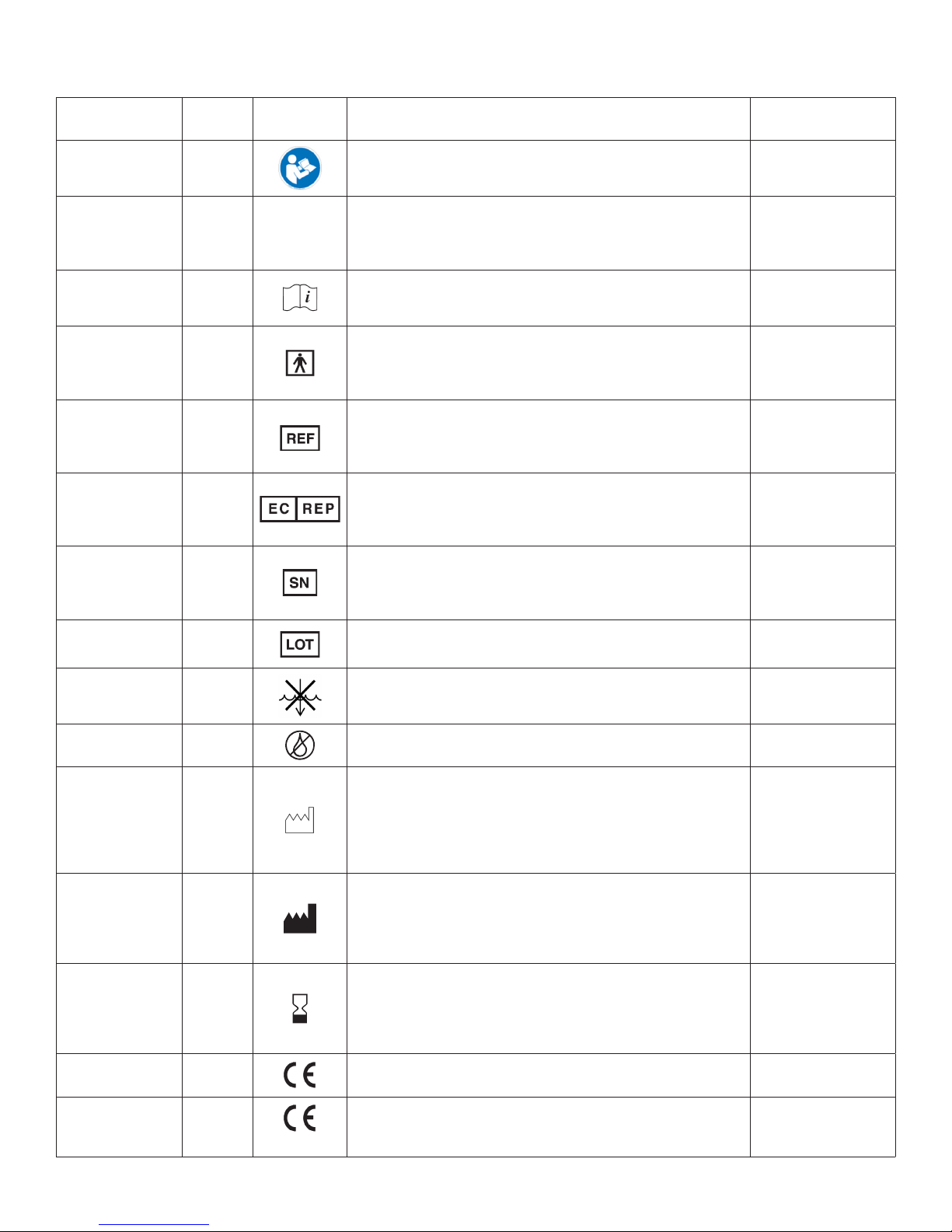
Symbol Denition
Name Ref#
(ISO 7000)2Symbol Description Use Standard
Refer to Instruction
Manual / Booklet
ISO-7010
M002
• Indicates a MANDATORY action for the user to consult the In-
structions For Use (IFU).
• Symbol must be blue, as shown.
IEC 60601-1:20051
Caution 0434A /
0434B CIndicates the need for the user to consult the Instructions For Use
(IFU) for important cautionary information such as
warnings and precautions that cannot, for a variety of reasons, be
presented on the device itself.
ISO 15223-1:20121
Consult
Instructions For
Use (IFU)
1641
Indicates the need for the user to consult the Instructions For Use
(IFU). Not required in conjunction with the Caution
symbol, if applicable.
ISO 15223-1:20121
Type BF
Applied Part 5333
Indicates a medical device complying with the specied require-
ments of IEC 60601-1 to provide a higher degree of protection
against electric shock than that provided by
Type B Applied Parts.
IEC 60601-1:2005
REF (Catalog #) 2493
• Indicates the manufacturer’s catalog number so that the medical
device can be identied.
• Per EN980:2008, the REF symbol may be used without
surrounding box.
ISO 15223-1:20121
Authorized
Representative
in the European
Community
N/A
Indicates the authorized representative in the European
Community. This symbol shall be accompanied by the name and
address of the authorized representative, adjacent to the symbol.
ISO 15223-1:20121
Serial # 2498
• Indicates the manufacturer’s serial number so that a
specic medical device can be identied.
• Per EN980:2008, the SN symbol may be used without
surrounding box.
ISO 15223-1:20121
Lot / Batch Code 2492 Indicates the manufacturer’s batch code so that the batch or lot
can be identied. ISO 15223-1:20121
Do Not Immerse in
any Liquid 5995 Indicates a medical device that is not to be immersed in any liquid. IEC 60335-2-15
Do Not Lubricate N/A Indicates a medical device that is not to be lubricated. N/A
Date of
Manufacture 2497
• Indicates the date when the medical device was
manufactured. The date is expressed as YYYY-MM (e.g. 2015-11)
or YYYY-MM-DD (e.g. 2015-11-29).
• If the symbol is lled (see Manufacturer symbol), both
the date of manufacture and the name/address of the manufac-
turer may be combined in one symbol.
ISO 15223-1:20121
Manufacturer 3082
• Indicates the medical device manufacturer. This symbol shall be
accompanied by the name and address of the manufacturer. The
date of manufacture may be combined with this symbol.
• When using MicroAire as the manufacturer, use the MicroAire
LLC symbol.
ISO 15223-1:20121
Use-By Date 2607
Indicates the date after which the medical device is not to be used.
This symbol shall be accompanied by a date to indicate that the
medical device should not be used after the end of the month
shown. The date is expressed as YYYY-MM (e.g. 2015-11) or YYYY-
MM-DD (e.g. 2015-11-29).
ISO 15223-1:20121
CE Mark for EU
Class I Products N/A European Conformity Mark Council Directive
93/42/EEC
CE Mark for EU
Class IIa and Higher
Products
N/A 0086
2013
European Conformity Mark
0086 = Notied Body Number
2013 = Year of CE Approval
Council Directive
93/42/EEC

4IM-5025 REV E
Name Ref#
(ISO 7000)2Symbol Description Use Standard
Humidity Limitation 2620
Indicates the range of humidity to which the medical device can
be safely exposed. The humidity limitations shall be indicated
adjacent to the upper and lower horizontal lines.
ISO 15223-1:20121
Atmospheric
Pressure
Limitation
2621
Indicates the range of atmospheric pressure to which the medical
device can be safely exposed. The atmospheric pressure
limitations shall be indicated adjacent to the upper and lower
horizontal lines.
ISO 15223-1:20121
Temperature
Limitation 0632 >Indicates the temperature limits to which the medical device
can be safely exposed. The upper and lower limits to temperature
shall be indicated adjacent to the upper and lower
horizontal lines.
ISO 15223-1:20121
Do Not Expose to
Stray Magnetic Fields N/A Indicates a medical device that is not to be exposed to stray
magnetic elds. N/A
N/A N/A Potential Equalization Terminal N/A
N/A N/A Do not allow ngers to contact moving parts. N/A
Prescription N/A Caution: Federal Law (U.S.A.) restricts this device to sale by or on
the order of a physician (or properly licensed practitioner).
FDA
Title 21, Chapter 1,
Subchapter H,
Part 801.15(F)
Dispose of per
WEEE Directive
2012/19/EU
N/A
Indicates a medical device that is not to be disposed of as
unsorted municipal waste. Medical device is to be disposed of
per WEEE Directive 2012/19/EU.
Council Directive
2012/19/EU
Dispose of per
WEEE Directive
2012/19/EU
N/A
Indicates a medical device that is not to be disposed of as
unsorted municipal waste. Medical device is to be disposed of
per WEEE Directive 2012/19/EU. This symbol is used in place of
the above symbol if the product entered the market after 13
August, 2005.
Council Directive
2012/19/EU
(Symbol: European
Standard EN 50419)
UL symbol N/A
E494242
MEDICAL-GENERAL MEDICAL EQUIPMENT AS TO ELECTRIC
SHOCK, FIRE, AND MECHANICAL HAZARDS ONLY. IN
ACCORDANCE WITH ANSI/AAMI ES 60601-1 (2005) + A1
(2012) + CAN/CSA C22.2 No. 60601-1 (2014) | Control
Number: E494242
UL
Irrigation Pump N/A Indicates Irrigation Pump Function N/A
Irrigation Pause/Run N/A /pIrrigation Pump Pause/Run (Normal Run) N/A
Surgical Instrument N/A Indicates Surgical Instrument Function N/A
Normal Run 5107B pRun Direction (Run in Forward or Reverse as Indicated) N/A
Standby 5009 X Switches Unit In and Out of Standby Mode N/A
Instrument
Speed Adjustment N/A Press to Adjust Instrument Speed (Variable in Steps) N/A
Irrigation Flow
Adjustment N/A Press to Adjust Irrigation Flow Rate (Variable in Steps) N/A
Direction of Rotation 0941 RIndicates Direction of Rotation N/A
Foot Control N/A Indicates Foot Control Related Function N/A

5IM-5025 REV E
PRODUCT CATALOG NUMBER (REF) DESCRIPTION
INSTRUCTIONS FOR USE WITH
COMPLETE LIST OF ACCESSORIES
AND TYPE BF APPLIED PARTS
REF PAL-650 PAL Powered Handpiece IM-PAL-650
REF 5006-PAL PAL Instrument Cable IM-PAL-650
REF 5000E Series 5000 Electric Motor Module, Throttle-less IM-5000E
REF 5000ET Series 5000 Electric Motor Module, With Throttle IM-5000E
REF 5641 Series 5000 SmartDriver DUO®e Dual Trigger Electric IM-5641
REF 5995U Series 5000 Solo™ Driver Handpiece IM-5995U
REF 5006-5000 Series 5000 Instrument Cable IM-5000E, IM-5641, IM-5995U
REF 5401 Series 5000 Electric Foot Pedal IM-5025
REF 5025-5401 Series 5000 Foot Pedal Cable IM-5025
REF 1000ET Series 1000 Electric Motor Module, With Throttle IM-1000 (IEC 60601-1 2nd Edition)
REF 5006-1000 Series 1000 Instrument Cable IM-1000
Instruments and their accessories are sold separately. Contact your MicroAire® Sales representative or MicroAire® Customer Service
at 1-800-722-0822 for a complete list of accessories and instruments available. Outside the USA, contact your nearest MicroAire
authorized distributor.
Compatible Instruments
DEFINITIONS: WARNING – CAUTION – NOTE
Please read this manual and follow its instructions carefully. The words WARNING, CAUTION and NOTE carry special meanings and
should be carefully reviewed.
WARNING: Used to indicate that the safety of the patient and hospital personnel could be involved.
CAUTION: Used to indicate special procedures or precautions that must be followed to avoid damaging the system
and instruments.
NOTE: Used to indicate the easiest means of carrying out techniques.
GENERAL WARNINGS
WARNING: Upon receipt and before each use, you should inspect the system and its components for visible damage.
Do not use if there is apparent damage to any component. Perform recommended maintenance as indicated in
the Instructions for Use. Failure to comply may result in healthcare professional and/or patient injury.
The MicroAire REF 5025 or REF 5020 Electric Instrument Control Console (“the Console”) is an electronic control system designed
to drive small power instrumentation in a wide variety of surgical applications. Intended users are surgeons, physician’s assistants,
orthopaedic operating room nurses and circulating nurses.
Indications for use and contraindications will be provided in the IFU for the instruments that are powered by the REF 5020 and REF
5025. See the Compatible Instruments section below.
Intended Use
Name Ref#
(ISO 7000)2Symbol Description Use Standard
Tube Holder
Adjustment N/A Irrigation Pump Tube Holder Adjustment for Large and Small Size
Irrigation Tubing N/A
CSA Mark N/A Canadian Standards Association Mark for Canada and U.S. CSA
USB Port N/A Universal Serial Bus Port USB 2.0
1 ISO 15223-1:2012 –“Medical devices – Symbols to be used with medical device labels, labelling and information to be supplied – Part 1: General requirements”
2 ISO 7000/IEC 60417 –“Graphical symbols for use on equipment – Registered symbols”

6IM-5025 REV E
WARNING: The healthcare provider performing any procedure is responsible for determining whether this is the appropriate
equipment/instrument for the specic procedure that is being performed for each patient. As the manufacturer,
MicroAire does not recommend surgical procedures or oer any guidance in such procedures.
WARNING: Only trained and experienced healthcare providers/professionals should use this medical equipment. Before
using any system component or any component that is compatible with this system read and understand the
Instructions for Use. Pay special attention to the WARNING information and familiarize yourself with the system
components prior to use. Failure to comply may result in patient and/or healthcare professional injury.
WARNING: Consult and Follow the appropriate Instructions for Use for the instrument to be used. See the table under
Compatible Instruments.
WARNING: Do not use this equipment or components in the presence of ammable anesthetic mixture with air or with
oxygen or nitrous oxide.
WARNING: AC mains disconnect must be achieved by removing cord from wall outlet. Ensure that the Console is positioned
so that the power cord can be unplugged.
WARNING: Use personal protective equipment as required. Failure to comply may result in patient and/or healthcare
professional injury.
WARNING: Cleaning and Sterilization of all system components used inside the sterile eld are required before each use.
See MicroAire’s Cleaning and Sterilization Procedures in the appropriate instrument Instructions for Use.
WARNING: Use only MicroAire approved accessories. Use of unapproved accessories may result in increased
electromagnetic emissions or decreased immunity of the system and will void the warranty. Do not modify
any accessory. Failure to comply may result in patient and/or healthcare professional injury.
WARNING: Do not place instruments, components or handpieces on the patient. Failure to comply may result in
patient injury.
WARNING: Do not place handpieces near or on magnetic pads or trays. Magnetic elds can create throttle
output of a Foot Pedal or handpiece switch and may cause the instrument or component to operate
inadvertently. Failure to comply may result in patient and/or healthcare professional injury.
WARNING: Do not allow ngers to contact moving parts.
WARNING: This product does not comply with the ATEX directive and must
not be used with explosive atmospheres.
WARNING: Irrigation must be used when cutting bone in order to ensure that the temperature at the cutting
accessory does not exceed 41°C / 105.8°F.
WARNING: Use only with a medically approved type SJT or equivalent three wire (protective earth) grounded
power cord rated for 125V or 250V AC, 10A, constructed with 18/3 AWG wires and an IEC 320 appliance
connector.
WARNING: DO NOT modify the ground connection or any portion of the Console power cord. Failure to comply
may result in healthcare professional injury.
WARNING: Grounding reliability can only be achieved when the equipment is connected to an equipment
receptacle marked as “Hospital Grade”.
WARNING: Anyone who connects additional equipment to the contact closure connector congures a medical
system, and is therefore responsible that the system complies with the requirements of clause 16 of
ANSI/AAMI/IEC ES60601-1:2005 + Am1 (2012).
WARNING: The USB port is to be used only for diagnostics and/or software upgrade by MicroAire approved
technicians only. The USB port must not be connected to any cable or device while in operation.
WARNING: If the Console reboots due to instrument overload or loss of electrical power, the Irrigation Pump
will be disabled when the Console restarts. The Irrigation Pump must be re-enabled via the
touchscreen before resuming use of the instrument. Failure to comply may result in patient injury.
WARNING: Do not use this equipment in the presence of ammable anesthetics.
WARNING: Modication of this equipment is not allowed.
WARNING: Electric Shock. Do not remove cover. Refer servicing to authorized MicroAire personnel only.
WARNING: Take special precautions with electromagnetic compatibility (EMC) when using the MicroAire Electric Instrument
Console. Ensure that the Console is installed and placed into service according to the EMC information contained
in the Instructions for Use.

7IM-5025 REV E
WARNING: The 5020/5025 Electric Instrument Control Console and associated instruments have been tested for use in the
vicinity of High Frequency Electrosurgical/ Electrocoagulation equipment. Use of such equipment in close
proximity to the MicroAire instruments or instrument cables may cause unintended interruptions or unintended
motion of durations up to 1 second. Place MicroAire Instruments on a safe surface when not in use. Do not place
MicroAire Instruments on the patient when not in use. Avoid entwining HF surgical cables with MicroAire
Instrument Cables.
WARNING: Portable RF communications equipment should be used no closer than 30 cm (12 inches) away from any part of
the 5020/5025 Console, its associated cables or the handpieces it is controlling. Otherwise degradation of the
performance of the PAL-650 or series 5000 instruments could result.
WARNING: Use of the 5020/5025 Console adjacent to or stacked with other equipment should be avoided because it could
result in improper operation. If such use is necessary, the 5020/5025 and the adjacent equipment should be
observed to verify that they are operating normally.
WARNING: The following items should be periodically inspected for signs of damage and repaired or replaced as needed to
ensure continued safety with regard to electromagnetic disturbances over the life of the system:
• 5020/5025 Electric Instrument Control Console:
- Proper Fit of the top cover to the chassis.
- Damage to the LCD Display
- Test that the Protective Earth Connection meets ES60601-1 requirements.
• Inspect the 5006-PAL instrument cables for signs of physical damage to the cable.
WARNING: The 5020 & PAL-650 Liposuction handpiece and the 5025 & Series 5000 Instrument System are suitable for use in
hospitals and surgery centers. These systems should not be used near Magnetic Resonance Imaging equipment.
CAUTION: Federal Law (U.S.A.) restricts this device to sale by or on the order of a physician (or properly licensed
practitioner).
CAUTION: Do not thread or twist the push/pull connectors on the cable(s) during installation or removal.
CAUTION: When connecting or disconnecting a cable(s) to the front of the Console, always hold the cable by its
connector. Failure to comply may result in damage to the cable or Console.
CAUTION: Cables that are connected to the front of the Console have keyed, push/pull type connectors that lock
into place. Do not force a connector into a Console port. Each connector and port has an alignment
mark to indicate proper cable orientation.
CAUTION: DO NOT sterilize the 5020/5025 Console or its power cord, or the 5401 Foot Pedal
- They may be wiped down with a germicidal cleaner. Take precautions to avoid allowing any moisture
inside of any Console opening and power cord.
CAUTION: DO NOT use aerosol sprays of any kind directly on the screen display of the Console. Clean by wiping
with a soft, damp cloth and drying with a soft dry cloth.
NOTE: When the Instrument Slider Bar is being adjusted, the number shows the desired maximum speed.
When the instrument is in use (rotating), it will show the commanded speed of the instrument as a
percentage of its rated speed.
NOTE: If the Console screen is touched in more than one place at the same time, an unintended button
activation may occur. Please make sure the settings are adjusted as required before operating the
accessories/ instruments.
NOTE: The Instrument Direction icon only changes direction of the pencil grip instruments. For all other instruments
this icon serves as an indicator to the user of which direction the instrument is currently running. Pressing the
direction icon when these instruments are connected results in an error tone and will not change the direction
of that instrument.
NOTE: Connection of the Potential Equalization Connector is not required for compliance with IEC 60601-1
or IEC 60601-1-2.
NOTE: The emissions characteristics of this product make it suitable for use in industrial areas and hospitals (CISPR 11
Class A). If it is used in a residential environment (for which CISPR 11 Class B is normally required) this equipment
might not oer adequate protection to radio frequency communication services. The user might be required to
take mitigation measures, such as relocating or re-orienting the equipment.
NOTE: Repairs or alterations to MicroAire® products made by anyone other than MicroAire® or an Authorized
MicroAire® Repair Facility will void that product’s warranty, and the customer will be responsible for any costs
related to returning the product to working condition.
NOTE: The Irrigation Pump is not intended for use with the PAL-650.

8IM-5025 REV E
Standby Button
Blinking when in
stand by , must press
and hold to power up
Foot Pedal Connector
(Not used with PAL-650) Handpiece connectors
Allows connection and running of
handpieces simultaneously
USB Serial Port
Communication port
used for software
upgrade(s)
Irrigation Pump
(Not used with PAL-650)
Color Touch Screen
Touch screen to control settings
FIGURE 1
Power Receptacle
Connect Console power
cord and connect to
facility power outlet
Irrigation Bag Pole-Mounting Bracket
(Not used with PAL-650)
Contact Closure
Used for control of MicroAire-
compatible suction pumps
Potential Equalization Connector
Used for common ground among
multiple instruments in procedure
FIGURE 2
REF 5020 / REF 5025 Instrument Control Console Features
Sytem Setup

9IM-5025 REV E
WARNING: Do not place instruments, components or handpieces on the patient. Failure to comply may result in
patient injury.
WARNING: Do not place handpieces near or on magnetic pads or trays. Magnetic elds can create throttle
output of a Foot Pedal or handpiece switch and may cause the instrument or component to operate
inadvertently. Failure to comply may result in patient and/or healthcare professional injury.
1. Place the Console on a sturdy, at surface near a hospital-grade outlet.
2. Install the power cord plug into the power receptacle on the Console.
3. Install the other end of the power cord into a hospital wall outlet.
4. Wait for the Console to initialize, then press and hold the blinking standby button to turn on the Console.
5. If using a Foot Pedal, plug the Foot Pedal cable into the port marked with a Foot Pedal symbol. Align
the marks and gently push the connectors together. Once correctly plugged in, the blue led light around the
connector will light up. Only one Foot Pedal may be connected to the Console at a time, but can be selected to
operate either of the Foot Pedal-compatible instruments.
6. Plug the handpiece cable(s) into the Console port(s) marked with a HANDPIECE symbol. Align the marks and
gently push the connectors together. Once correctly plugged in, the blue led light around the connector will
light up. Two handpieces may be connected to the Console and operated simultaneously.
7. Plug the other end of the handpiece cable(s) into the instrument(s). See Instructions For Use supplied with
each handpiece for connection information.
8. Attach the cutting accessory to the handpiece(s). See the Instructions for Use supplied with each handpiece
or attachment for cutting accessory installation information.
9. If required, install the irrigation tubing into the Console Irrigation Pump by following the instructions in the
“Irrigation Settings”section in the Instructions for Use manual.
Instrument Duty Cycles
• The REF 5020 & REF 5025 Electric Instrument Control Consoles are designed for Continuous Operation. Each
Instrument has its own Duty Cycle.
• The REF PAL-650 has an operating duty cycle of 2 hours ON, 2 hours OFF.
• The REF 5000E, 5000ET, 5641 and 5995-U instruments have an operating duty cycle of 1 minute ON, 1 minute
OFF, for 6 cycles maximum.
• The REF 1000E and 1000ET instruments are designed to operate for 1 minute of continuous use and should be
allowed to cool to room temperature. (IEC 60601-1 2nd Edition)
WARNING: Irrigation must be used when cutting bone in order to ensure that the temperature at the cutting
accessory does not exceed 41°C / 105.8°F.
NOTE: If using the Console Irrigation Pump, install the Irrigation Pole (supplied with the 5025 Console) to
the mounting bracket on the back of the Console. Hang the irrigation bag from the pole and follow
the irrigation instructions as stated below.
CAUTIONS:
• Do not thread or twist the push/pull connectors on the cable(s) during installation or removal.
• When connecting or disconnecting a cable(s) to the front of the Console, always hold the cable by its
connector. Failure to comply may result in damage to the cable or Console.
• Cables that are connected to the front of the Console have keyed, push/pull type connectors that lock into
place. Do not force a connector into a Console port. Each connector and port has an alignment mark to
indicate proper cable orientation.
Connecting the Instruments

10 IM-5025 REV E
Load the section of tubing between the two
connectors into the Irrigation Pump to prevent
tubing from advancing inadvertently
æå
Tube Loading Area
Between two arrows
FIGURE 4
5
Insert spike into bag by
slightly twisting the bag
spike while penetrating the
irrigation bag as shown
1Open irrigation
area door
4
3
2
This end of the irrigation
tubing will disperse the
irrigation uid
Load Irrigation tubing
making note of the
pump direction
(See notes 1-3)
To close Irrigator Pump
door, push down on the
door until it snaps into place
NOTE: This end of the
irrigation tubing will
be connected to the
irrigation bag
6
Open Irrigator Pump
door by lifting the door
as shown
FIGURE 3
Loading irrigation tubing
NOTE: The Irrigation Pump is not intended for use with the PAL-650.
1. Open the irrigation area door.
2. Open irrigator pump door by lifting/clicking up on the beige indicated area of the irrigator cover to allow ample room to
install irrigation tubing. (NOTE: Irrigation Pump runs in the counterclockwise direction).
3. Verify that the pump tube holder is set to the small tube position. If adjustment is required, see instructions under “Tube
Holder Repositioning”. Load irrigation tubing by placing the tubing inside the Irrigation Pump. Make sure that the end of the
tubing to be attached to the instrument is positioned on the proper side as noted below. When loading the Tubing, make
sure to load only the proper section of tubing into the Irrigation Pump as shown below in Figure 3.
4. Once irrigation tubing is properly loaded, close the irrigator pump door by pushing down until the door locks into place,
securing the tubing.
5. Insert spike into the irrigation bag with the bag spike-end of the Tubing as shown below in Figure 3.
6. Place Irrigation tubing into the instrument irrigation clip as instructed in the Instructions for Use supplied with each hand-
piece or attachment-for-cutting accessory installation information.
7. To prime the Irrigation Pump, follow the instructions in Figures 3 and 4.
WARNING: Do not allow ngers to contact moving parts.
WARNING: This product does not comply with the ATEX directive and must not be used with explosive atmospheres.
Irrigation
Bag
11IM-5025 REV E
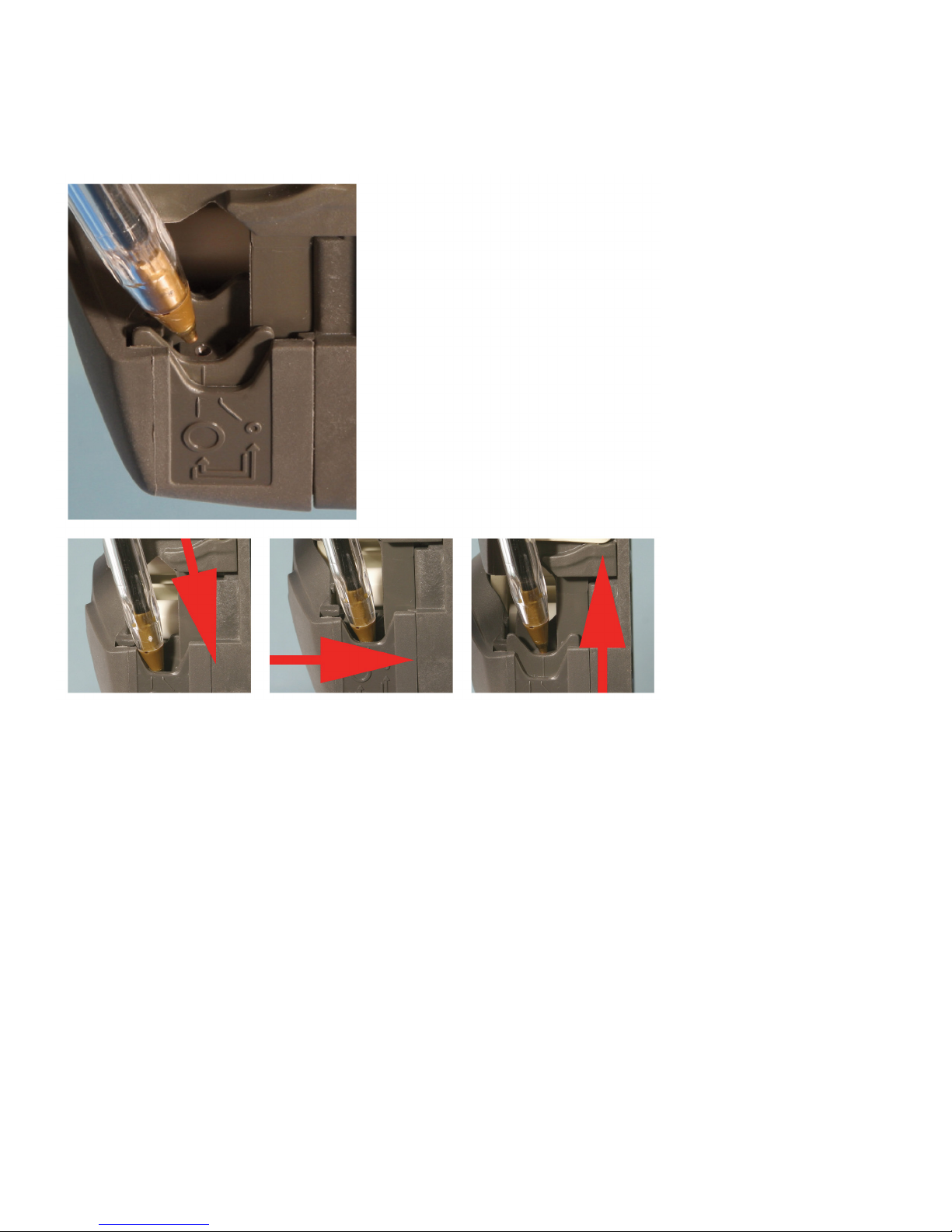
Tube holder repositioning for use with Irrigation Pump
To change from the large tube to the small tube setting
Switch o the pump before changing the tube holder position. Use a pointed device such as a ball-point pen to reposition the
lower tube holders on both sides of the pumphead.
• Lift the ip top until fully open.
• Place the pointed device pointing
down into the small depression pictured here.
• Press down and slightly away from the front of the pumphead, as shown in
the rst picture above.
• Maintain the angled downward pressure and push away from the front of the
pumphead. The jaw clicks into a new position.
• Release the pressure. The jaw rises into its correct alignment. If it does
not rise, repeat the procedure, being sure to maintain downward pressure
until release.
• Adjust the tube holder on the other side of the pumphead in the same way.
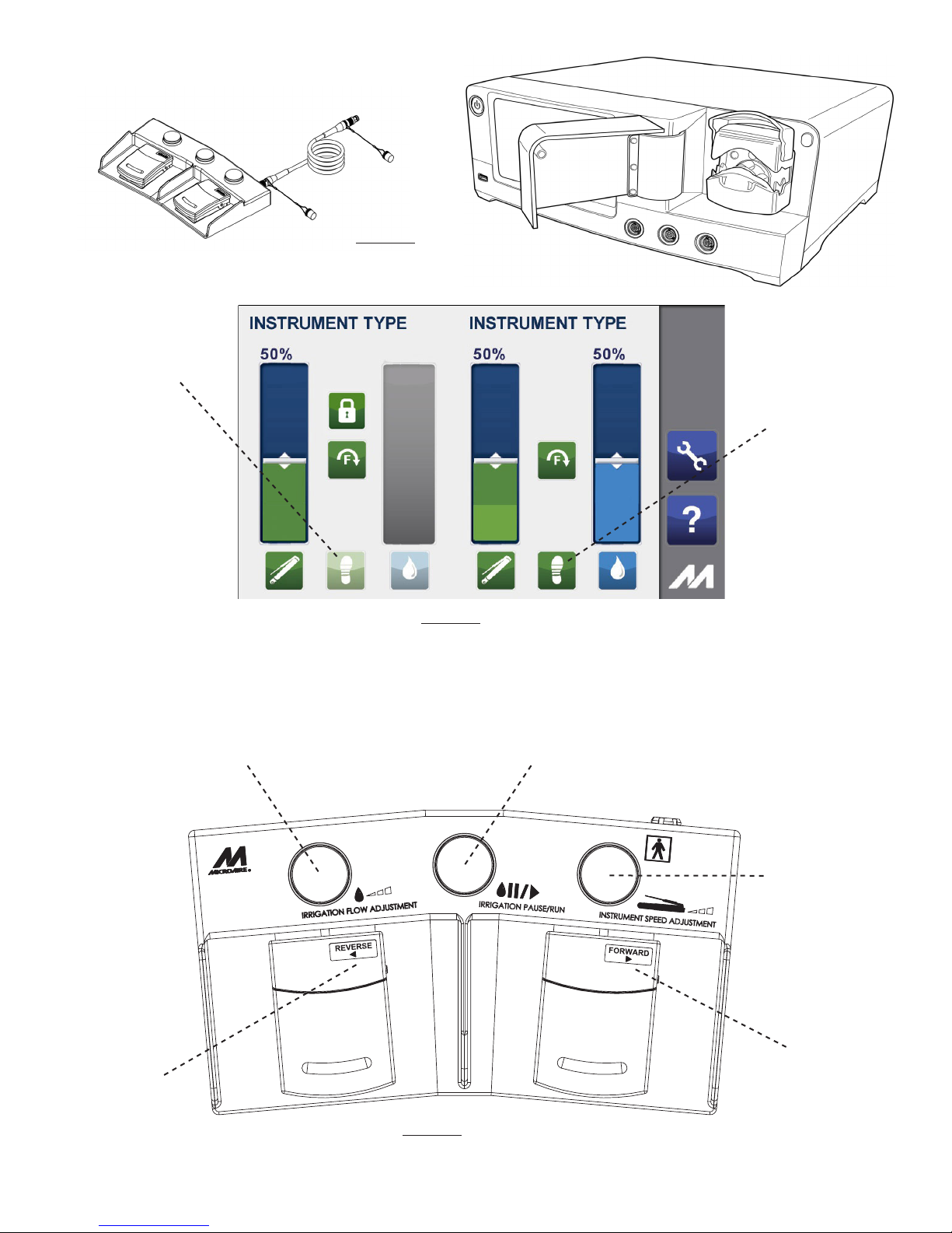
Connecting a Foot Pedal Control
CAUTION: Use only a MicroAire REF 5401 Foot Control Pedal and REF 5025-5401 Cable with the REF 5025 and REF 5020
Electric Instrument Console. Use of other Foot Pedal controllers will void warranty and may damage
instrument Console.
Plug the Foot Pedal Cable into the Foot Control Pedal and then plug the other end into the Console port marked with the Foot
Pedal symbol as shown in Figure 5.
To activate the Foot Pedal, press the Foot Pedal Control icon. Press again to inactivate the Foot Pedal as shown in Figure 6.
The Foot Pedal icon does not respond if pressed while the instrument is running.
NOTE: The Foot Pedal icon is only visible for instruments that are able to be run by the Foot Pedal. If the icon is not
present Foot Pedal control is not available for that instrument.
NOTE: Foot Pedal can only control one instrument at a time. If the Foot Pedal is active for Instrument 1 and you wish
to change to Instrument 2, make sure that neither connected instrument is running, then press the Foot Pedal
icon on the instrument of your choice to activate the Foot Pedal for that instrument.
12 IM-5025 REV E
á
á
FIGURE 5
To activate the Foot
Pedal control, press
the dim Foot Pedal
icon. To inactivate,
press again.
FIGURE 6
The bright Foot Pedal
icon indicates that the
Foot Pedal is active.
á
This button controls the irrigation ow.
Press to increase the ow rate in increments of 10%.
This Foot Pedal
is depressed to run
the instrument in
reverse (counter-
clockwise) direction.
This Foot Pedal is
depressed to run the
instrument in forward
(clockwise) direction.
This button controls
the instrument speed.
Press to increase the
speed rate in
increments of 10%.
This button controls the Irrigation Pump and acts as a pause and run switch.
Press once to pause irrigation and then again to resume irrigation.
FIGURE 7
Foot Pedal Control Denition
See Figure 7 below for guidelines on the button and pedal congurations of your Foot Pedal control.
13IM-5025 REV E
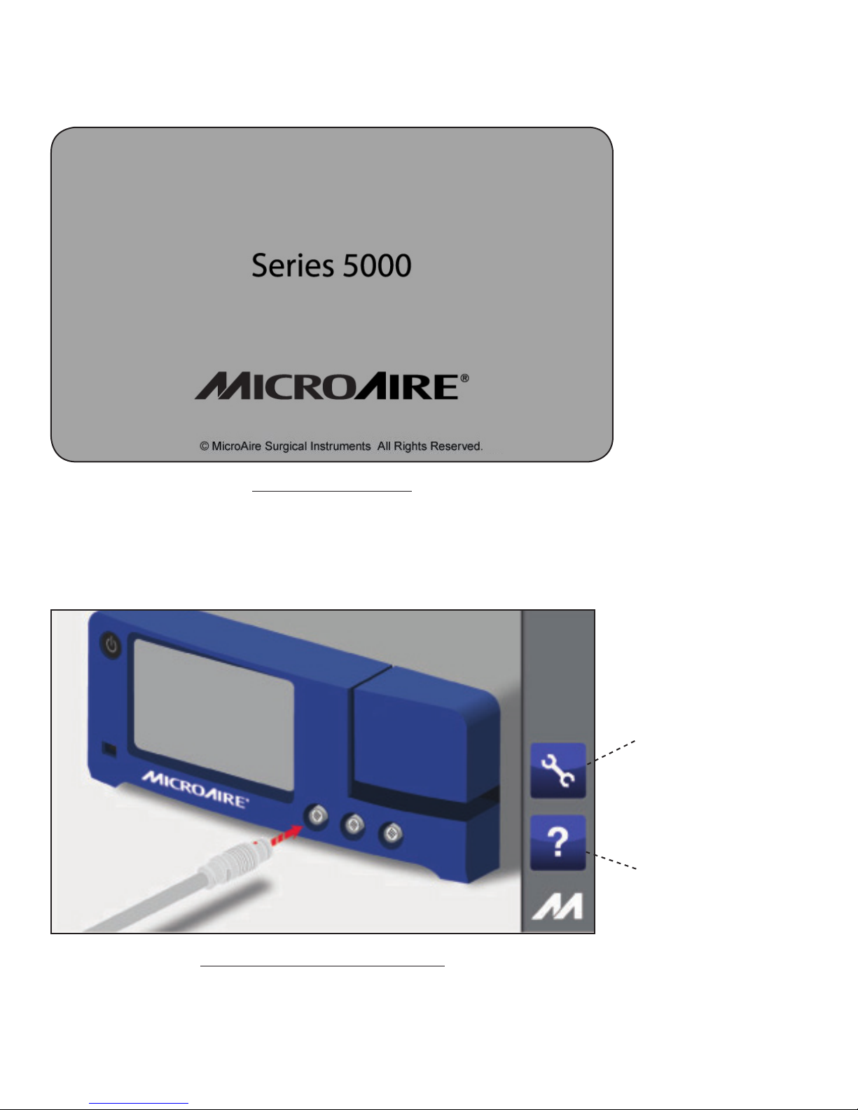
REF 5020 / REF 5025 Operation
Press the blinking standby button and this screen is momentarily displayed while the Console powers up.
FIGURE 8 - Power Up Screen
If there is a failure of the operating system on your Console, Error 12 will be displayed.
Press this button to
access the Help area
Press this button
to access the
Settings area
If no handpieces are connected to the Console during the initial power up, the following screen will appear:
FIGURE 9 - Plug in Handpiece Cable Screen
To access the instrument control screen, you must connect an instrument to the Console.
From this screen you may access the HELP screen/menu or the SETTINGS screen/menu.

14 IM-5025 REV E
Alert Help:
All Alert pop-ups will contain the Help Icon. Pressing the Help Icon will bring up and Alert Help Screen.
See the Troubleshooting Guide on page 25 for details on each alert message.
FIGURE 10
FIGURE 11
15IM-5025 REV E
FIGURE 12
FIGURE 13

16 IM-5025 REV E
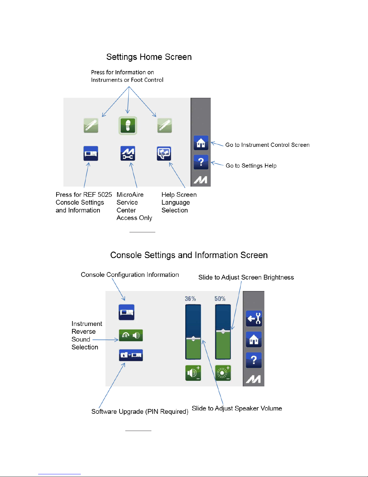
Adjusting Language Settings
The manufacturer’s default language is set to English. If you wish to change your language settings, please follow the instructions
below.
To access the Settings area press the “user settings”icon:
To access the Languages menu press the“language settings”icon:
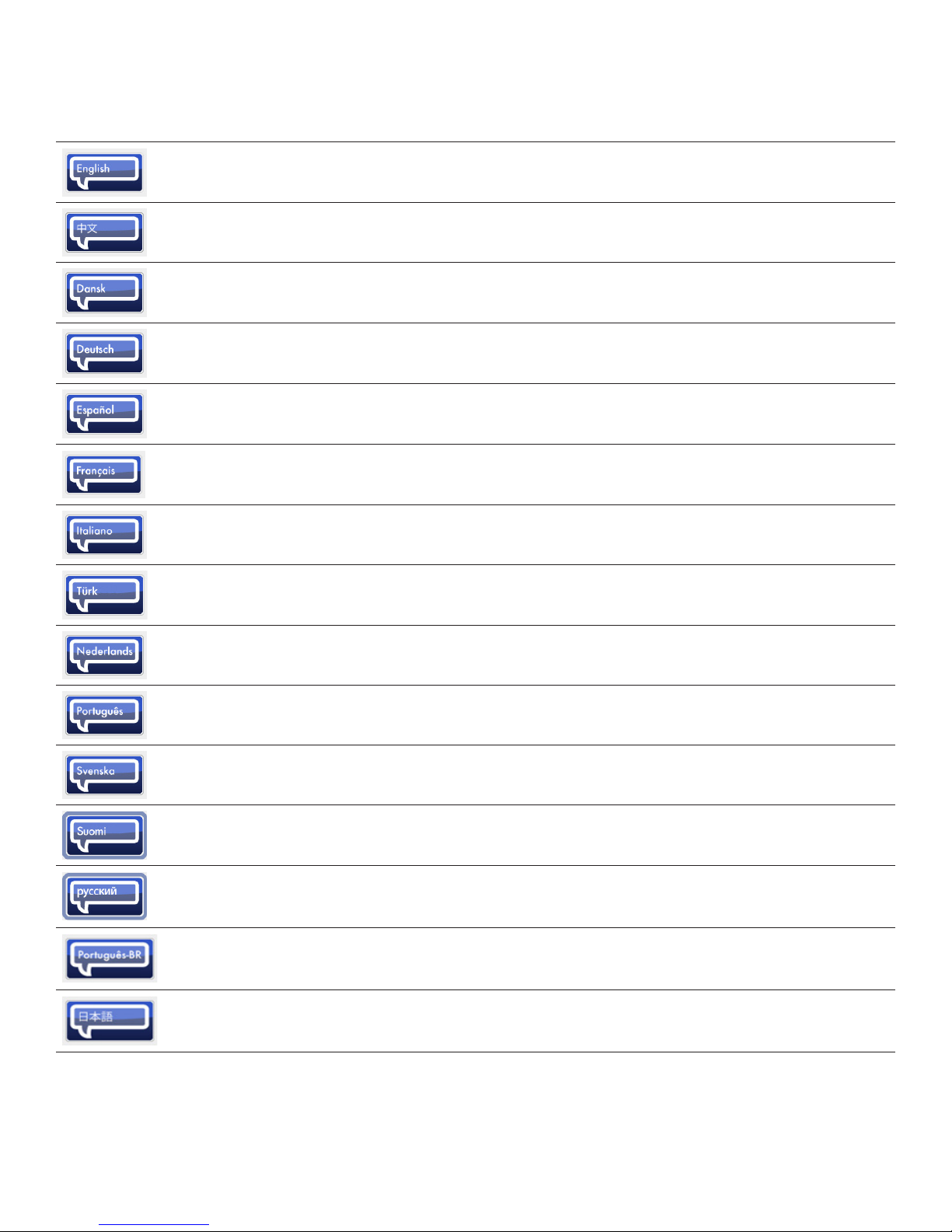
The following screen opens and allows you to pick your language. The current active language icon will be bright, and all other
languages available will be shown, but will be dimly lit.
To select another language, press the appropriate language icon.
To conrm your language change, press the“conrm action/ok” button. To return to the Settings screen and leave the language
choice unchanged, press the “take no action/back”button as noted below.
Current active
language setting
FIGURE 14
Other languages
available
To conrm your
language choice
To return to the Settings
menu without making
a language change
17IM-5025 REV E
ICON NAME DEFINITIONS
ENGLISH Select English Help Screens
CHINESE Select Chinese Help Screens
DANISH Select Danish Help Screens
GERMAN Select German Help Screens
SPANISH Select Spanish Help Screens
FRENCH Select French Help Screens
ITALIAN Select Italian Help Screens
TURKISH Select Turkish Help Screens
DUTCH Select Dutch Help Screens
PORTUGUESE Select Portuguese Help Screens
SWEDISH Select Swedish Help Screens
FINNISH Select Finnish Help Screens
RUSSIAN Select Russian Help Screens
PORTUGUESE
(BRAZIL) Select Brazilian Portuguese Help Screens
JAPANESE Select Japanese Help Screens
Icon Denitions
18 IM-5025 REV E
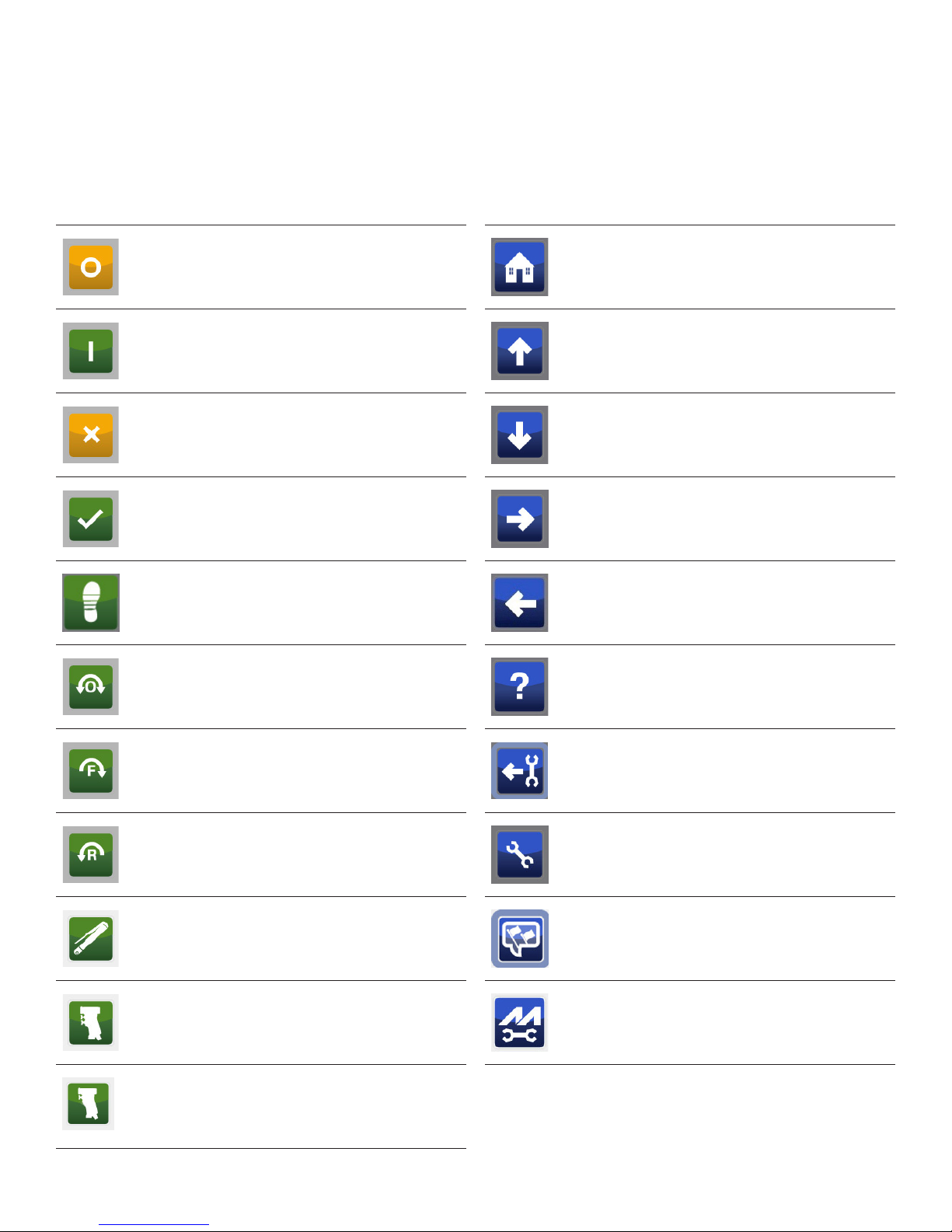
Icon Denitions - Continued
This section provides a complete list of the icons as they appear on the screens within the graphical user interface. All icons can
appear in one of three states as outlined: (1) brightly lit icon identies that the icon is active, (2) dimly lit icon identies that the
icon is not active at this time, (3) brightly lit icon with a halo around it identies that you are currently pressing that icon.
ICON NAME DEFINITIONS ICON NAME DEFINITIONS
OFF Turn o selected feature HOME Returns to the home screen
from any window
ON Turn on selected feature UP Scroll up one page in the help
screens
TAKE NO
ACTION/
GO BACK
Cancel and close window DOWN Scroll down a page in the help
screen
CONFIRM
ACTION/OK Select and conrm action FORWARD Move to next screen
Foot Pedal
CONTROLS Adjust Foot Pedal settings GO BACK Go back to previous screen
OSCILLATE Set handpiece to oscillate (ro-
tate back and forth) HELP View Console help screen and
settings
FORWARD Set handpiece to forward
(rotate in clockwise direction)
USER SETTINGS
RETURN
Return from user settings
screen
REVERSE Set handpiece to reverse (rotate
in counterclockwise direction)
USER
SETTINGS
View and adjust Console user
settings
HANDPIECE
INDICATOR Pencil-Style handpiece LANGUAGE
SETTING
Change current language
setting to new language
HANDPIECE
INDICATOR SmartDriver DUOe™ handpiece MICROAIRE®
SERVICE
Restricted access - password
protected for MicroAire
approved Service Centers only
HANDPIECE
INDICATOR
SmartDriver™ Single Trigger
handpiece

19IM-5025 REV E
ICON NAME DEFINITIONS ICON NAME DEFINITIONS
IRRIGATOR
SETTINGS Adjust irrigator settings SOFTWARE
UPGRADE
Software Upgrade (MicroAire
Authorized Service Only)
Console
SETTINGS
View and adjust Console display
settings DISCONNECT Disconnect all instruments &
Foot Pedal from Console
ADJUST
BRIGHTNESS
View and adjust Console
brightness Foot Pedal Icon for Foot Pedal information
ADJUST
SOUNDS View and adjust Console sounds INSTRUMENT A Icon for Instrument A
information
MUTE Mute Reverse Audio INSTRUMENT B Icon for Instrument B
information
REVERSE
DIRECTION
AUDIO
Reverse Audio set up icon IRRIGATOR Icon for irrigator pump
information
ONE TIME Play reverse audio one time
only
CONTINUOUS
PLAY
Continuous play of reverse
audio
HANDPIECE
INDICATOR Solo™ handpiece
LOCK
INDICATOR
Indicates that handpiece is
locked and in safe position
HANDPIECE
INDICATOR PAL® handpiece
Icon Denitions - Continued
This manual suits for next models
1
Table of contents


