5
DIP SWITCHES
LEFT/RIGHT OUTPUT MIC/LINE:
DIP switches 1 and 2 adjust the left
and right outputs for line- or mic-level operation.
MIC 1/MIC 2 Ducking:
When ducking is on, the SCM262 will automat-
ically lower the gain of all STEREO inputs when someone is speaking into
one of the microphones.
DUCKING LEVEL:
Adjusts the amount of STEREO channel gain re-
duction when ducking is activated.
STEREO 3 JUKEBOX MUTE:
This DIP switch turns the Juke Box
Mute feature on or off. When on, any source connected to STEREO 3 will
mute STEREO 1 and 2 inputs.
PHANTOM POWER:
When in the down position, this switch activates
a 12 V phantom power source for condenser microphones. Phantom
power does not affect the operation of balanced, dynamic microphones,
so one can be connected to the SCM262 in combination with a condenser
microphone.
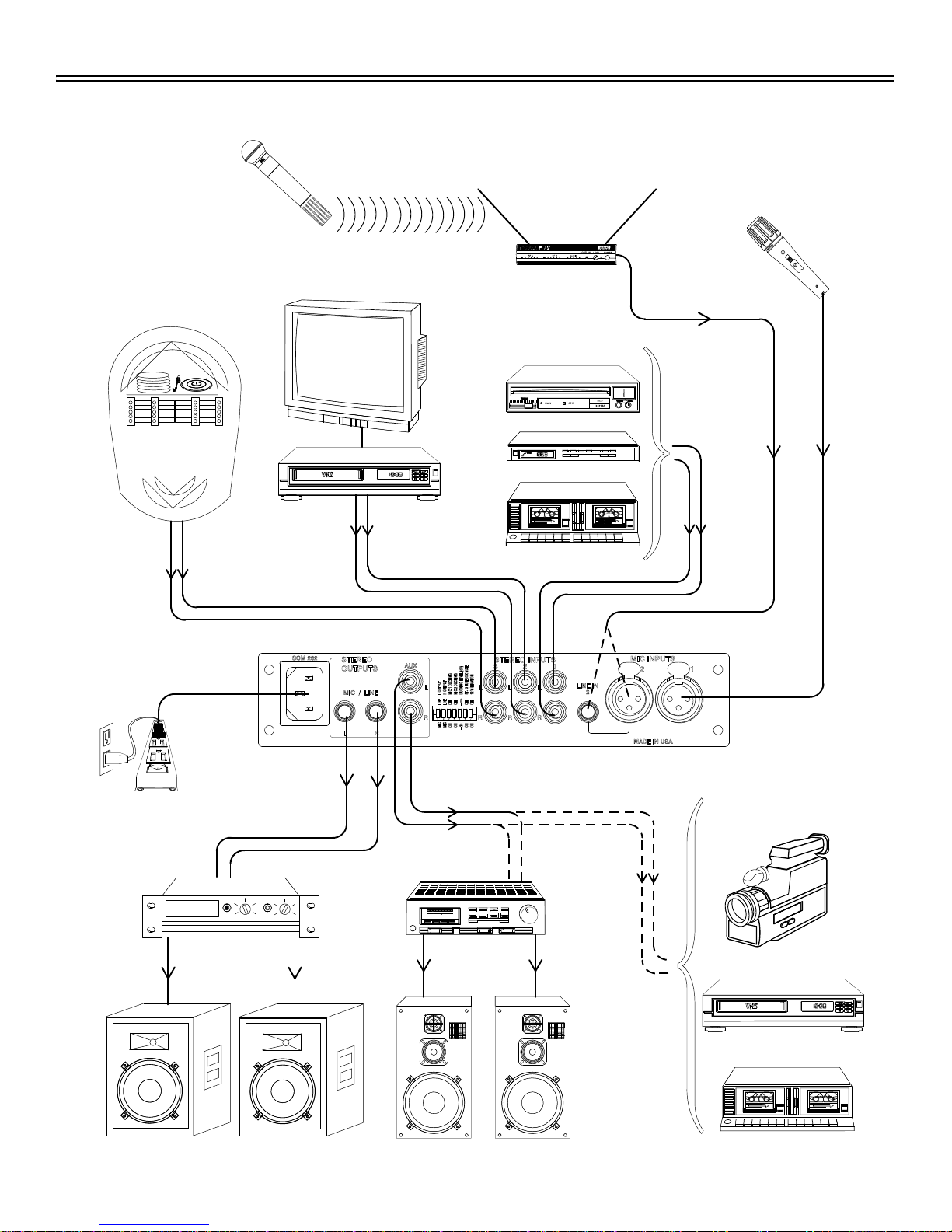
APPLICATIONS
General Application
This is a general setup for most situations which require the combined
use of professional microphones and consumer stereo equipment. Using
this general setup, there are several other options available for further ad-
justing the SCM262 for your sound system. See the diagram on the fac-
ing page.
1. Turn all gain controls counterclockwise.
2. Connect L/R STEREO INPUTS of the SCM262 to the L/R stereo
outputs of the desired stereo audio equiment (CD players, VCRs,
televisions, juke boxes, etc.).
3. Connect microphone(s) to the MIC INPUTS on the SCM262.
4. For microphones which require phantom power, such as con-
denser microphones, place DIP switch 7 in the down position
(phantom power on).
5. Connect the L/R outputs of the SCM262 to the L/R inputs of the
amplifier.
NOTE: If you are using a consumer stereo amplifier, use the
AUX OUTs. If you are using a professional audio power
amplifier, use the LINE OUTs. The MIC/LINE and AUX
OUTPUTs can be used simultaneously to feed two separate
amplifiers.
6. Apply power to the mixer by connecting the supplied power cable
between the power connector on the mixer and the appropriate
AC power supply. The green POWER LED will illuminate to indi-
cate that the mixer is powered on.
NOTE: The SCM262 has no power switch. It is designed to
be plugged into a power strip which supports the whole sound
system. A typical power strip will have a power switch, so that
when the power strip is powered on, the SCM262 is powered
on.
Paging with Ducking Application
With Ducking on, the SCM262 will automatically sense when someone
is talking into one of the microphones and lower the volume of the music
so the talker can be heard more clearly. Once the talker is finished, the
music resumes.
NOTE: Use a microphone with an ON/OFF or pushbutton
switch for the Paging with Ducking Application. A microphone
without a switch will false-trigger, causing unwanted
interruptions in the program material.
1.
Connect the SCM262 to the sound system as described in
Gen-
eral Application.
2. Set DIP switch 3 or 4 to the down position to activate ducking for
microphone channel 1 or 2, respectively.
3.
Set DIP switch 5 position. The
Down position sets the ducking so
that the program sound is lowered 20 dB when someone uses a
microphone. The Up position sets the ducking so that the pro-
gram sound is muted when someone uses a microphone.
Jukebox Mute Application
In this application, designed primarily for Jukeboxes, any sound
source connected to the STEREO 3 channels will automatically mute any
sound coming over the STEREO 1 and 2 channels. This way, a CD play-
er can be playing music, and then when someone plays a song on the
Jukebox, the SCM262 will automatically mute the CD player channels
and switch to the Jukebox. STEREO 1 and 2 channels will remain muted
for about 30 seconds after program material is finished, to allow the juke-
box time to move on to the next song.
1.
Connect the SCM262 to the sound system as described in
Gen-
eral Application.
2. Connect the L/R audio outputs of the jukebox to the L/R inputs of
STEREO 3.
NOTE: This feature is designed especially for use with
jukeboxes, but will work for any equipment connected to
STEREO 3.
3. Set DIP Switch 6 to the down position (Jukebox Mute on).
NOTE: If the ducking application is used in conjunction with the
Jukebox Mute application, then activated microphones will
mute or duck the STEREO 3 input.
DIP
SWITCH
FUNCTION POSITION
UP (default) DOWN
1 LEFT OUTPUT MIC/LINE Line Mic
2 RIGHT OUTPUT MIC/LINE Line Mic
3 MIC 1 DUCKING Off On
4 MIC 2 DUCKING Off On
5 DUCKING LEVEL –∞–20 dB
6 STEREO 3 JUKEBOX MUTE Off On
7 12 V PHANTOM Off On
LINE
LINE
OFF
OFF
OFF
OFF
-∞
MIC
MIC
ON
ON
ON
ON
-
20
LOUTPUT
ROUTPUT
MIC 1 DUCKING
MIC 2 DUCKING
DUCKING LEVEL (dB)
ST. 3 JUKEBOX MUTE
12 V PHANTOM
DOWN
UP
12346
57