MICROELETTRICA MC40-SEF User manual

MC40-SEF
Doc. N° MO-0475-ING
Copyright 2012
FW: 1320.38.01.x
Date
06.09.2022
Rev.
1
Pag.
1
of
36
MICROPROCESSOR
OVERCURRENT and EARTH FAULT
RELAY
TYPE
OPERATION MANUAL

MC40-SEF
Doc. N° MO-0475-ING
Copyright 2012
FW: 1320.38.01.x
Date
06.09.2022
Rev.
1
Pag.
2
of
36
1. General Utilization and Commissioning Directions ________________________________________________________3
1.1 - Storage and Transportation______________________________________________________________________3
1.2 - Installation __________________________________________________________________________________3
1.3 - Electrical Connection ___________________________________________________________________________3
1.4 - Measuring Inputs and Power Supply _______________________________________________________________3
1.5 - Outputs Loading ______________________________________________________________________________3
1.6 - Protection Earthing ____________________________________________________________________________3
1.7 - Setting and Calibration _________________________________________________________________________3
1.8 - Safety Protection______________________________________________________________________________3
1.9 - Handling ____________________________________________________________________________________3
1.10 - Maintenance ________________________________________________________________________________4
1.11 - Waste Disposal of Electrical & Electronic Equipment __________________________________________________4
1.12 - Fault detection and repair ______________________________________________________________________4
2. General Characteristics _____________________________________________________________________________5
2.1 - Power Supply ________________________________________________________________________________5
2.2 - Operation and Algorithms _______________________________________________________________________6
2.2.1 - Reference Input Values ____________________________________________________________________________________ 6
2.2.2 - Input quantities __________________________________________________________________________________________ 6
2.2.3 - Time Current Curves IEC (TU1029 Rev.0) _____________________________________________________________________ 8
2.2.4 - Time Current Curves IEEE (TU1028 Rev.0)_____________________________________________________________________ 9
3. Functions and Settings (Function) ____________________________________________________________________10
3.1 - T> (F49) - Thermal Image protection level_________________________________________________________10
3.1.1 - Thermal Image Curves (TU0445 Rev.0) ______________________________________________________________________ 11
3.2 - I> (1F51) - First overcurrent protection level _______________________________________________________12
3.3 - I>> (2F51) - Second overcurrent protection level ___________________________________________________13
3.4 - IH (3F51) - Third overcurrent protection level ______________________________________________________14
3.4.1 –Automatic doubling or Overcurrent thresholds on current inrush___________________________________________________ 14
3.5 - Io> (1F51N) - First Earth Fault protection level _____________________________________________________15
3.6 - Io>> (2F51N) - Second Earth Fault protection level __________________________________________________15
3.7 - IoH (3F51N) - Third Earth Fault protection level _____________________________________________________16
3.8 –So> - Sensitive Earth Fault protection level ________________________________________________________16
3.9 - BF (F51BF) - Breaker Failure____________________________________________________________________17
3.10 - RTD - Remote Trip __________________________________________________________________________17
3.11 - I.R.F. - Internal Relay Failure __________________________________________________________________17
3.12 - CBMng –Close Breaker Manage ________________________________________________________________18
3.13 - Osc - Oscillographic Recording _________________________________________________________________18
3.14 - Comm –Communication Parameters ____________________________________________________________19
3.15 - LCD –Display and Buzzer operation _____________________________________________________________19
4. Logic Blocking of Functions _________________________________________________________________________20
4.1 - Blocking Outputs _____________________________________________________________________________20
4.2 –Blocking Inputs______________________________________________________________________________20
5. Output Relays ___________________________________________________________________________________20
6. Digital Inputs____________________________________________________________________________________21
7. Self-diagnostic___________________________________________________________________________________21
8. Relay Management _______________________________________________________________________________22
9. Signalizations ___________________________________________________________________________________23
10. Keyboard Buttons _______________________________________________________________________________23
11. Serial Communication Port ________________________________________________________________________24
11.1 - Main RS485 Serial Communication Port __________________________________________________________24
11.2 - Communication Port on Front Face Panel _________________________________________________________25
12. Menu and Variables ______________________________________________________________________________26
12.1 - Real Time Measurements _____________________________________________________________________26
12.2 - Meas (Instantaneous Measurements) ____________________________________________________________26
12.3 - Counter (Operation Counters)__________________________________________________________________26
12.4 - LastTrip (Event Recording) ____________________________________________________________________27
12.5 - R/W Set (Programming / Reading the Relay Settings) _______________________________________________28
12.5.1 - CommAdd (Communication Address) _______________________________________________________________________ 28
12.5.2 - Time/Date (Time/Date) __________________________________________________________________________________ 28
12.5.3 - RatedVal (Rated Input Values) ____________________________________________________________________________ 28
12.5.4 - Function (Functions) ____________________________________________________________________________________ 29
12.6 - RelayCfg (Relay Configuration) _________________________________________________________________31
12.7 - Commands ________________________________________________________________________________31
12.8 - Info&Ver (Firmware - Info&Version) _____________________________________________________________31
13. Keyboard Operational Diagram _____________________________________________________________________32
14. Password ______________________________________________________________________________________33
14.1 - MS-Com Password___________________________________________________________________________33
15. Maintenance ___________________________________________________________________________________33
16. Power Frequency Insulation Test ____________________________________________________________________33
17. Connection Diagram _____________________________________________________________________________34
18. Overall Dimensions ______________________________________________________________________________34
19. Direction for Pcb's Draw-Out and Plug-In _____________________________________________________________35
19.1 - Draw-Out _________________________________________________________________________________35
19.2 - Plug-In ___________________________________________________________________________________35
20. Electrical Characteristics __________________________________________________________________________36

MC40-SEF
Doc. N° MO-0475-ING
Copyright 2012
FW: 1320.38.01.x
Date
06.09.2022
Rev.
1
Pag.
3
of
36
1. General Utilization and Commissioning Directions
Always make reference to the specific description of the product and to the Manufacturer's instruction.
Carefully observe the following warnings.
1.1 - Storage and Transportation
must comply with the environmental conditions stated on the product's instruction or by the applicable IEC
standards.
1.2 - Installation
must be properly made and in compliance with the operational ambient conditions stated by the
Manufacturer.
1.3 - Electrical Connection
must be made strictly according to the wiring diagram supplied with the Product, to its electrical
characteristics and in compliance with the applicable standards particularly with reference to human safety.
1.4 - Measuring Inputs and Power Supply
carefully check that the value of input quantities and power supply voltage are proper and within the
permissible variation limits.
1.5 - Outputs Loading
must be compatible with their declared performance.
1.6 - Protection Earthing
When earthing is required, carefully check its effectiveness.
1.7 - Setting and Calibration
Carefully check the proper setting of the different functions according to the configuration of the protected
system, the safety regulations and the co-ordination with other equipment.
1.8 - Safety Protection
Carefully check that all safety means are correctly mounted, apply proper seals where required and
periodically check their integrity.
1.9 - Handling
Notwithstanding the highest practicable protection means used in designing M.S. electronic circuits, the
electronic components and semiconductor devices mounted on the modules can be seriously damaged by
electrostatic voltage discharge which can be experienced when handling the modules.
The damage caused by electrostatic discharge may not be immediately apparent, but the design reliability and
the long life of the product will have been reduced. The electronic circuits reduced by M.S. are completely safe
from electrostatic discharge (8 kV IEC 255.22.2) when housed in their case; withdrawing the modules without
proper cautions expose them to the risk of damage.
a.
Before removing a module, ensure that you are at the same electrostatic potential as the equipment by
touching the case.
b.
Handle the module by its front-plate, frame, or edges of the printed circuit board. Avoid touching the
electronic components, printed circuit tracks or connectors.
c.
Do not pass the module to any person without first ensuring that you are both at the same electrostatic
potential. Shaking hands achieves equipotential.
d.
Place the module on an antistatic surface, or on a conducting surface which is at the same potential as
yourself.
e.
Store or transport the module in a conductive bag.
More information on safe working procedures for all electronic equipment can be found in BS5783
and IEC 147-OF.

MC40-SEF
Doc. N° MO-0475-ING
Copyright 2012
FW: 1320.38.01.x
Date
06.09.2022
Rev.
1
Pag.
4
of
36
1.10 - Maintenance
Make reference to the instruction manual of the Manufacturer; maintenance must be carried-out by specially
trained people and in strict conformity with the safety regulations.
1.11 - Waste Disposal of Electrical & Electronic Equipment
(Applicable throughout the European Union and other European countries with separate collection program).
This product should not be treated as household waste when you wish dispose of it. Instead, it should be
handed over to an applicable collection point for the recycling of electrical and electronic equipment.
By ensuring this product is disposed of correctly, you will help prevent potential negative consequence to the
environment and human health, which could otherwise be caused by inappropriate disposal of this product. The
recycling of materials will help to conserve natural resource.
1.12 - Fault detection and repair
Internal calibrations and components should not be altered or replaced.
For repair, please ask the Manufacturer or its authorized Dealers.
Misapplication of the above warnings and instruction relieves the Manufacturer of any liability.

MC40-SEF
Doc. N° MO-0475-ING
Copyright 2012
FW: 1320.38.01.x
Date
06.09.2022
Rev.
1
Pag.
5
of
36
2. General Characteristics
The MC is a very innovative and versatile line of Protective Relays which takes advantage of the long and
successful experience coming from the M-Line.
The main features of the MC-Line relays are:
Compact draw-out execution for Flush Mounting or for assembly in 19” 3U chassis for 19” Rack systems.
User friendly front face with 2x8 characters LCD Display, four signal Leds, four keys for complete local
management and 9-pin socket for local RS232 serial communication.
Four user programmable Output Relays. On request one of the Output Relays can be replaced by a Can Bus
port for control of additional I/O modules.
Three optoisolated, self-powered Digital Inputs.
RS485 communication port (independent from the RS232 port on front panel)
Totally draw-out execution with automatic C.T. shorting device.
Input currents are supplied to 4 current transformers: measuring phase currents.
Current inputs can be 1 or 5A: selection between 1A or 5A is made by movable jumpers provided on the Relay
card. (See Fig 1)
The Measuring Ranges of the different inputs
respectively are:
Phase Currents
:
(0.1-40) In
Make electric connection in conformity with the
diagram reported on relay's enclosure.
Check that input currents are same as reported on
the diagram and on the test certificate.
2.1 - Power Supply
The auxiliary power is supplied by a built-in module fully isolated a self-protected.
The relay can be fitted with two different types of power supply:
Type 1
24V(-20%) / 110V(+15%) a.c.
24V(-20%) / 125V(+20%) d.c.
Type 2
80V(-20%) / 220V(+15%) a.c.
90V(-20%) / 250V(+20%) d.c.
Before energizing the unit check that supply voltage is within the allowed limits.

MC40-SEF
Doc. N° MO-0475-ING
Copyright 2012
FW: 1320.38.01.x
Date
06.09.2022
Rev.
1
Pag.
6
of
36
2.2 - Operation and Algorithms
2.2.1 - Reference Input Values
Display
Description
Setting Range
Step
Unit
I1
100
A
Rated Primary current of phase C.T.
1
-
9999
1
A
I2
5
A
Rated Secondary current of phase C.T.
1
-
5
1/5
A
IN1
1
A
Rated Primary neutral
1
-
9999
1
A
In
100
A
Reference primary current of the relay
1
-
9999
1
A
Freq
50
Hz
System rated frequency
50
-
60
10
Hz
TW
60
sec
Warming-up time constant for Thermal Image
60
-
3600
1
sec
Ib
105
%In
Maximum admissible continuous overload for Thermal Image
50
-
130
0.1
%In
2.2.2 - Input quantities
2.2.2.1 - Mains Frequency (Freq)
The relay can operate either in 50Hz or 60Hz systems.
The rated Mains Frequency “Freq” must be set accordingly.
2.2.2.2 - Phase Current inputs (I1)
The relay directly displays the r.m.s. value of the Phase Currents “IA”, “IB”, “IC”, “IN”, flowing in the
Primary of the input Current Transformers and refers all its measurements to that value.
To make the relay properly working with any C.T., when programming the relay settings, input the value
“I1“ of the primary current of the phase C.Ts
The measure are not displayed below
:
< 5% In
2.2.2.3 - Earth Fault Current Input (IN1)
Same as for the Phase Currents, the relay directly displays the r.m.s. value of the Neutral Current flowing
at the Primary of the Current Transformers.
The measure are not displayed below
:
< 1% On

MC40-SEF
Doc. N° MO-0475-ING
Copyright 2012
FW: 1320.38.01.x
Date
06.09.2022
Rev.
1
Pag.
7
of
36
rs
atTKB
1
Is
I
A
t(I) +••
+
−
=α
2.2.2.4 - Algorithm of the time current curves
The Time Current Curves are generally calculated with the following equation :
(1)
where :
t(I) = Actual trip time delay when the input current equals “I”
I = Maximum of the three input currents.
Is = Set minimum pick-up level
K =
Ts= Set time delay : t(I) = Tswhen
tr = Operation time of the output relay on pick-up (7ms).
The parameters “A” and “a” have different values for the different Time Current Curves.
Curve Name
Curve Identifier
A
B
a
IEC A Inverse
A
0.14
0
0.02
IEC B Very Inverse
B
13.5
0
1
IEC C Extremely Inverse
C
80
0
2
IEEE Moderate Inverse
MI
0.0104
0.0226
0.02
IEEE Short Inverse
SI
0.00342
0.00262
0.02
IEEE Very Inverse
VI
3.88
0.0963
2
IEEE Inverse
I
5.95
0.18
2
IEEE Extremely Inverse
EI
5.67
0.0352
2
The maximum measuring current is “40xIn” for phase elements and “10xOn” for the neutral
element.
1
a110A−
−
10
II
s
=

MC40-SEF
Doc. N° MO-0475-ING
Copyright 2012
FW: 1320.38.01.x
Date
06.09.2022
Rev.
1
Pag.
8
of
36
2.2.3 - Time Current Curves IEC (TU1029 Rev.0)

MC40-SEF
Doc. N° MO-0475-ING
Copyright 2012
FW: 1320.38.01.x
Date
06.09.2022
Rev.
1
Pag.
9
of
36
2.2.4 - Time Current Curves IEEE (TU1028 Rev.0)
MC40-SEF
Doc. N° MO-0475-ING
Copyright 2012
FW: 1320.38.01.x
Date
06.09.2022
Rev.
1
Pag.
10
of
36
3. Functions and Settings (Function)
3.1 - T> (F49) - Thermal Image protection level
FuncEnab
→
Enable
[Disable / Enable]
Options
→
No Param
No Parameters
TripLev
→
Tal
50.00
%Tb
(50.00 110.00)
step
1
%Tb
→
Tst
100.00
%Tb
(10.00 100.00)
step
1
%Tb
Timers
→
No Param
No Parameters
Description of variables
FuncEnab
:
If disable the function is deactivated.
Tal
:
Thermal pre-alarm temperature.
Tst
:
Reset level.
Alarm when
:
The temperature exceeded level “Tal”
When the function is tripped
:
Signalization
=
Led “Trip” is illuminated
Last Trip
=
Is recorded
Reset when
:
Returns in normal condition.
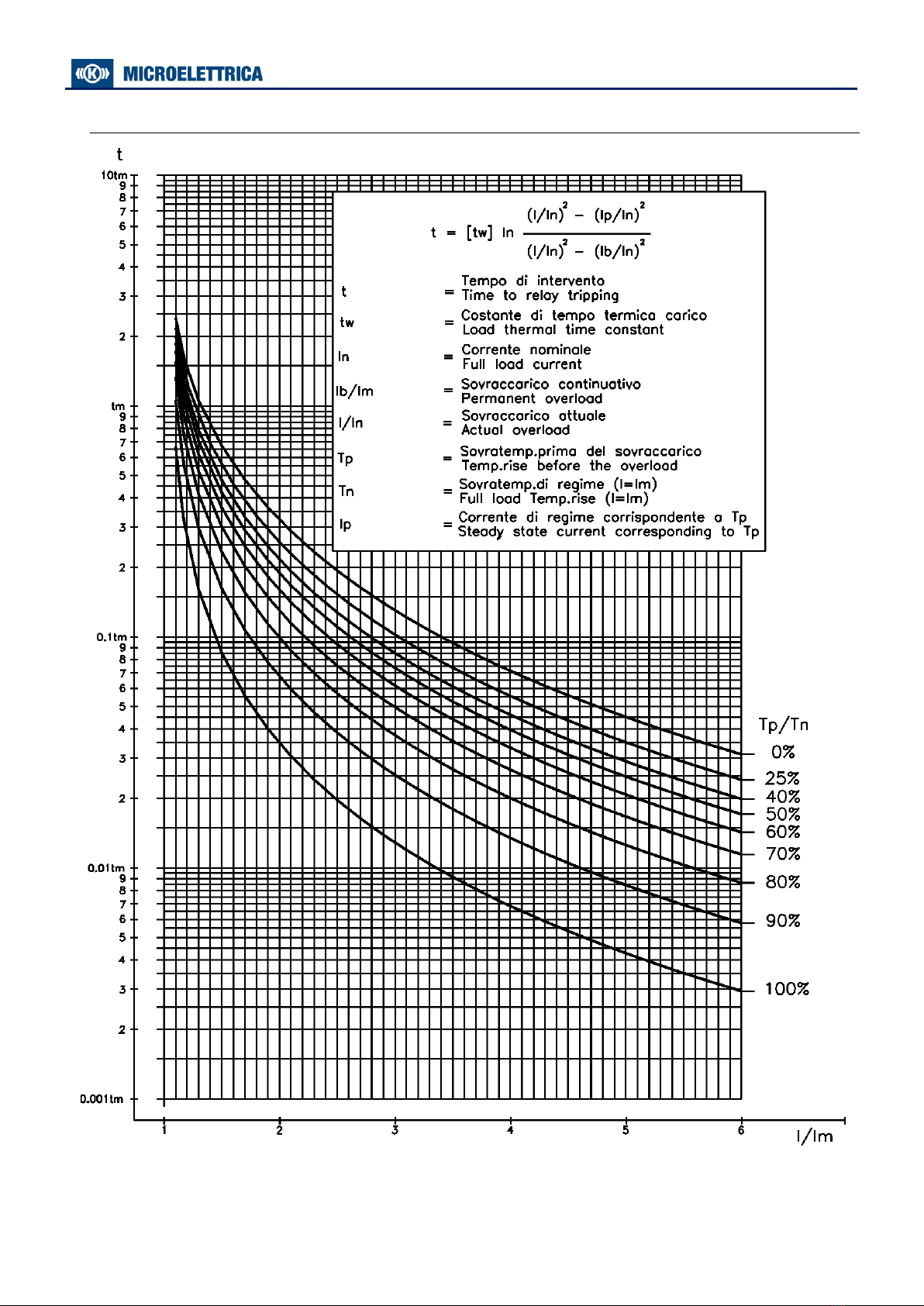
Warming-up is computed proportionally to the square of the largest phase current “I”.
-Allowed overloading time (See Curve)
The trip time delay “t”of the thermal element, depends on the warming-up time constant
“tw”, on the previous thermal status (Ip/In)2, on the admissible continuous overload (Ib) and, of
course, on the actual load (I)
tw
=
Warming-up time constant
(60-3600) s.
I
=
Largest of the three phase currents
Ip
=
Preheating current: Steady-State Current corresponding to the thermal status
existing at the moment when the current is increased to the overload value “I”
Ib
=
Continuously admissible current
(50-130) %In, step 0.1%In
In
=
Rated primary current of phase C.Ts
n
=
Natural logarithm
Reset takes please when the simulated temperature drops below the programming level [Tst].
An alarm signal is issued when the computed warming exceeds the set percentage “Tal” of the Full
Load temperature “Tb”.
:where
(Ib/In)(I/In) (Ip/In)(I/In)
twt22
22
−
−
= n
MC40-SEF
Doc. N° MO-0475-ING
Copyright 2012
FW: 1320.38.01.x
Date
06.09.2022
Rev.
1
Pag.
11
of
36
3.1.1 - Thermal Image Curves (TU0445 Rev.0)

MC40-SEF
Doc. N° MO-0475-ING
Copyright 2012
FW: 1320.38.01.x
Date
06.09.2022
Rev.
1
Pag.
12
of
36
3.2 - I> (1F51) - First overcurrent protection level
FuncEnab
→
Enable
[Disable / Enable]
Options
→
TCC
D
[D / A / B / C / MI / VI / I / EI / / SI ]
→
BI
Disable
[Disable / Enable]
→
Trg
Enable
[Disable / Enable]
TripLev
→
I>
0.5
In
(0.10 4.00)
step
0.01
In
Timers
→
tI>
2.00
s
(0.05 60.00)
step
0.01
s
Description of variables
FuncEnab
:
If disable the function is deactivated
TCC
:
Time current curves
D
=
Independent Definite Time
A
=
IEC A Inverse
B
=
IEC B Very Inverse
C
=
IEC C Extremely Inverse
MI
=
IEEE Moderate Inverse Curve
VI
=
IEEE Very Inverse Curve
I
=
IEEE Inverse Curve
EI
=
IEEE Extremely Inverse Curve
SI
=
IEEE Short Inverse Curve
BI
:
Operation controlled by Blocking Digital Input
Trg
:
Function operation triggers the oscillographic wave form capture
(see § Oscillographic Recording)
I>
:
Trip level (limited to 40 times In)
tI>
:
Trip time delay
Trip when
:
The current trip level is exceeded for time “tI>”.
When the function is tripped
:
Signalization
=
Led “Trip” is illuminated
Last Trip
=
Is recorded
Function reset when
:
The current drop below 95% I>.
Led reset when
:
push-button is pressed

MC40-SEF
Doc. N° MO-0475-ING
Copyright 2012
FW: 1320.38.01.x
Date
06.09.2022
Rev.
1
Pag.
13
of
36
3.3 - I>> (2F51) - Second overcurrent protection level
FuncEnab
→
Enable
[Disable / Enable]
Options
→
BI
Disable
[Disable / Enable]
→
2xI
Disable
[Disable / Enable]
→
Trg
Enable
[Disable / Enable]
TripLev
→
I>>
2.00
In
(0.50 40.00)
step
0.01
In
Timers
→
tI>>
1.00
s
(0.05 60.00)
step
0.01
s
→
t2xI
0.10
s
(0.02 9.99)
step
0.01
s
Description of variables
FuncEnab
:
If disable the function is deactivated
BI
:
Operation controlled by Blocking Digital Input
2xI
:
Automatic threshold doubling on inrush
Trg
:
Function operation triggers the oscillographic wave form capture
(see § Oscillographic Recording)
I>>
:
Trip level (limited to 40 times In)
tI>>
:
Trip time delay
t2xI
:
Trip time delay
Trip when
:
The current trip level is exceeded for time “tI>>”.
When the function is tripped
:
Signalization
=
Led “Trip” is illuminated
Last Trip
=
Is recorded
Function reset when
:
The current drop below 95% I>>.
Led reset when
:
push-button is pressed
MC40-SEF
Doc. N° MO-0475-ING
Copyright 2012
FW: 1320.38.01.x
Date
06.09.2022
Rev.
1
Pag.
14
of
36
3.4 - IH (3F51) - Third overcurrent protection level
FuncEnab
→
Enable
[Disable / Enable]
Options
→
BI
Disable
[Disable / Enable]
→
2xI
Enable
[Disable / Enable]
→
Trg
Enable
[Disable / Enable]
TripLev
→
IH
5.00
In
(0.50 40.00)
step
0.01
In
Timers
→
tIH
0.05
s
(0.05 60.00)
step
0.01
s
→
t2xI
0.10
s
(0.02 9.99)
step
0.01
s
Description of variables
FuncEnab
:
If disable the function is deactivated
BI
:
Operation controlled by Blocking Digital Input
2xI
:
Automatic threshold doubling on inrush
Trg
:
Function operation triggers the oscillographic wave form capture
(see § Oscillographic Recording)
IH
:
Trip level (limited to 40 times In)
t2xI
:
Trip time delay
tIH
:
Trip time delay
Trip when
:
The current trip level is exceeded for time “tIH”.
When the function is tripped
:
Signalization
=
Led “Trip” is illuminated
Last Trip
=
Is recorded
Function reset when
:
The current drop below 95% IH.
Led reset when
:
push-button is pressed
3.4.1 –Automatic doubling or Overcurrent thresholds on current inrush
For some of the phase Overcurrent functions it is possible to have the set trip level [Is] automatically
doubled when strong inrush current is detected.
If at circuit Breaker switch-on (i.e. when the input current rises from zero to a minimum measurable value)
the current increases from 0 to 1.5 times the rated value [In] in less than 60ms, the set minimum pick-up
level [Is] is dynamically doubled ([Is]→[2Is]) and keeps this value until the input current drops below
1.25xIn or the set time [t2xI] has elapsed.
This functionality is very useful to avoid spurious tripping of the instantaneous or short-time delayed
Overcurrent elements that could be experienced at switch-on of reactive loads like Transformer or
Capacitors.
MC40-SEF
Doc. N° MO-0475-ING
Copyright 2012
FW: 1320.38.01.x
Date
06.09.2022
Rev.
1
Pag.
15
of
36
3.5 - Io> (1F51N) - First Earth Fault protection level
FuncEnab
→
Enable
[Disable / Enable]
Options
→
TCC
D
[D / A / B / C / I / VI / EI / MI / SI ]
→
BI
Disable
[Disable / Enable]
→
Trg
Enable
[Disable / Enable]
TripLev
→
Io>
0.10
Ion
(0.01 4.00)
step
0.01
Ion
Timers
→
tIo>
2.00
s
(0.05 60.00)
step
0.01
s
Description of variables
FuncEnab
:
If disable the function is deactivated
TCC
:
Time current curves
D
=
Independent Definite Time
A
=
IEC A Inverse
B
=
IEC B Very Inverse
C
=
IEC C Extremely Inverse
MI
=
IEEE Moderate Inverse Curve
VI
=
IEEE Very Inverse Curve
I
=
IEEE Inverse Curve
EI
=
IEEE Extremely Inverse Curve
SI
=
IEEE Short Inverse Curve
BI
:
Operation controlled by Blocking Digital Input
Trg
:
Function operation triggers the oscillographic wave form capture
(see § Oscillographic Recording)
Io>
:
Trip level
tIo>
:
Trip time delay
Trip when
:
The current trip level is exceeded for time “tIo>”.
When the function is tripped
:
Signalization
=
Led “Trip” is illuminated
Last Trip
=
Is recorded
Function reset when
:
The current drop below 95% Io>.
Led reset when
:
push-button is pressed
3.6 - Io>> (2F51N) - Second Earth Fault protection level
FuncEnab
→
Enable
[Disable / Enable]
Options
→
BI
Disable
[Disable / Enable]
→
Trg
Enable
[Disable / Enable]
TripLev
→
Io>>
0.50
Ion
(0.01 9.99)
step
0.01
Ion
Timers
→
tIo>>
1.00
s
(0.05 60.00)
step
0.01
s
Description of variables
FuncEnab
:
If disable the function is deactivated
BI
:
Operation controlled by Blocking Digital Input
Trg
:
Function operation triggers the oscillographic wave form capture
(see § Oscillographic Recording)
Io>>
:
Trip level
tIo>>
:
Trip time delay
Trip when
:
The current trip level is exceeded for time “tIo>>”.
When the function is tripped
:
Signalization
=
Led “Trip” is illuminated
Last Trip
=
Is recorded
Function reset when
:
The current drop below 95% Io>.
Led reset when
:
push-button is pressed
MC40-SEF
Doc. N° MO-0475-ING
Copyright 2012
FW: 1320.38.01.x
Date
06.09.2022
Rev.
1
Pag.
16
of
36
3.7 - IoH (3F51N) - Third Earth Fault protection level
FuncEnab
→
Enable
[Disable / Enable]
Options
→
BI
Disable
[Disable / Enable]
→
Trg
Enable
[Disable / Enable]
TripLev
→
IoH
2.00
Ion
(0.01 9.99)
step
0.01
Ion
Timers
→
tIoH
0.10
s
(0.05 60.00)
step
0.01
s
Description of variables
FuncEnab
:
If disable the function is deactivated
BI
:
Operation controlled by Blocking Digital Input
Trg
:
Function operation triggers the oscillographic wave form capture
(see § Oscillographic Recording)
IoH
:
Trip level
tIoH
:
Trip time delay
Trip when
:
The current trip level is exceeded for time “tIoH”.
When the function is tripped
:
Signalization
=
Led “Trip” is illuminated
Last Trip
=
Is recorded
Function reset when
:
The current drop below 95% IoH.
Led reset when
:
Push-button is pressed
3.8 –So> - Sensitive Earth Fault protection level
FuncEnab
→
Enable
[Disable / Enable]
Options
→
BI
Disable
[Disable / Enable]
→
Trg
Enable
[Disable / Enable]
TripLev
→
So>
2.00
mA
(2 200)
step
0.1
mA
Timers
→
tSo>
0.10
s
(0.05 60.00)
step
0.01
s
Description of variables
FuncEnab
:
If disable the function is deactivated
BI
:
Operation controlled by Blocking Digital Input
Trg
:
Function operation triggers the oscillographic wave form capture
(see § Oscillographic Recording)
So>
:
Trip level
tSo>
:
Trip time delay
Trip when
:
The current trip level is exceeded for time “tSo>”.
When the function is tripped
:
Signalization
=
Led “Trip” is illuminated
Last Trip
=
Is recorded
Function reset when
:
The current drop below 95% So>.
Led reset when
:
push-button is pressed

MC40-SEF
Doc. N° MO-0475-ING
Copyright 2012
FW: 1320.38.01.x
Date
06.09.2022
Rev.
1
Pag.
17
of
36
3.9 - BF (F51BF) - Breaker Failure
FuncEnab
→
Enable
[Disable / Enable]
Options
→
TrR
Relay1
Relay1 –Relay2 –Relay3 –Relay4
TripLev
→
No Param
No Parameters
Timers
→
tBF
0.20
s
(0.05 0.75)
step
0.01
s
Description of variables
FuncEnab
:
If disable the function is disactivated
TrR
:
Output relay programmed for trip command to the Circuit Breaker
tBF
:
Trip time delay
Operation: If after the time “tBF” from pick-up of the programmed relay “TrR” the current measured still
exceeds 5%In, the output relay associated to the “BF” function is operated (relay another than TrR).
3.10 - RTD - Remote Trip
Remote trip is controlled via the Digital Input D2.
FuncEnab
→
Disable
[Disable / Enable]
Options
→
No Param
No Parameters
TripLev
→
No Param
No Parameters
Timers
→
No Param
No Parameters
Description of variables
FuncEnab
:
If disable the function is deactivated
3.11 - I.R.F. - Internal Relay Failure
FuncEnab
→
No Param
No Parameters
Options
→
Opl
NoTrip
[NoTrip / Trip]
TripLev
→
No Param
No Parameters
Timers
→
No Param
No Parameters
Description of variables
Opl
:
The variable “Opl” can be programmed to trip the output relays same as the other
protection functions (OpI = TRIP), or to only operate the “IRF” signal led without
tripping the output relays (OpI = NoTRIP).
Trip when
:
The Internal failure is detected. (see § self-diagnostic)
When the function is tripped
:
Signalization
=
Led “PWR/I.R.F.” flashing
Last Trip
=
Is recorded
Function reset when
:
Returns in normal condition
Led reset when
:
Push-button is pressed
MC40-SEF
Doc. N° MO-0475-ING
Copyright 2012
FW: 1320.38.01.x
Date
06.09.2022
Rev.
1
Pag.
18
of
36
3.12 - CBMng –Close Breaker Manage
FuncEnab
→
No Param
No Parameters
Options
→
No Param
No Parameters
TripLev
→
No Param
No Parameters
Timers
→
tcmd
0.10
s
(0.10 5.00)
step
0.1
s
→
tC
0.10
s
(0.10 5.00)
step
0.1
s
Description of variables
tcmd
:
C/B closing output command duration
tC
:
Maximum admissible delay for detection of status signal after C/B operation.
3.13 - Osc - Oscillographic Recording
FuncEnab
→
Enable
[Disable / Enable]
Options
→
Trg
Trip
[Disable / Start / Trip / Ext.Inp.]
TripLev
→
No Param
No Parameters
Timers
→
tPre
0.30
s
(0.10 0.50)
step
0.1
s
→
tPost
0.30
s
(0.10 1.50)
step
0.1
s
Description of variables
FuncEnab
:
If disable the function is disactivated
Trg
:
Disab
=
Function Disable (no recording)
Start.
=
Trigger on time start of protection functions
Trip
=
Trigger on trip (time delay end) of protection functions
Ext.Inp.
=
Trigger from the Digital Input D3
tPre
:
Recording time before Trigger
tPost
:
Recording time after Trigger
When the option “Start” or “Trip” is selected:
The oscillographic recording is started respectively by the “Time Start” or by the “Time End” of any of the
functions that have been programmed to Trigger the Wave Form Capture (I>, I>>, IH, Io>, Io>>, IoH).
The “Osc” Function includes the wave Form Capture of the input quantities (IA, IB, IC, IN) and can totally
store a record of 3 seconds.
The number of events recorded depends on the duration of each individual recording (tPre + tPost).
In any case the number of events stored cannot exceed ten (10 x 0.3 sec).
Any new event beyond the 3 sec capacity of the memory, cancel and overwrites the former records (FIFO
Memory).

MC40-SEF
Doc. N° MO-0475-ING
Copyright 2012
FW: 1320.38.01.x
Date
06.09.2022
Rev.
1
Pag.
19
of
36
3.14 - Comm –Communication Parameters
FuncEnab
→
No Param
No Parameters
Options
→
LBd
9600
[9600 / 19200 / 38400 / 57600]
→
RBd
9600
[9600 / 19200]
→
Mod
8,n,1
[8,n,1 / 8,o,1 / 8,e,1]
→
RPr
Modbus
[Iec103 / Modbus]
TripLev
→
No Param
No Parameters
Timers
→
No Param
No Parameters
Description of variables
LBd
:
Local Baud Rate (Front panel RS232 communication speed)
RBd
:
Remote Baud Rate
(Rear panel terminal blocks RS485 communication speed)
Mod
:
Remote mode (communication parameters)
Note: Any change of this setting becomes valid at the next power on
RPr
:
Remote Protocol
3.15 - LCD –Display and Buzzer operation
FuncEnab
→
No Param
No Parameters
Options
→
BkL
Auto
[Auto / On]
TripLev
→
No Param
No Parameters
Timers
→
No Param
No Parameters
Description of variables
Key
:
Buzzer “Beep” on operation of Keyboard buttons.
BkL
:
LCD Backlight continuously “ON” or switched-on Automatically on operation of
Keyboard buttons.

MC40-SEF
Doc. N° MO-0475-ING
Copyright 2012
FW: 1320.38.01.x
Date
06.09.2022
Rev.
1
Pag.
20
of
36
4. Logic Blocking of Functions
4.1 - Blocking Outputs
The instantaneous element of each of the protection functions (1F50, 2F50, 3F50, 1F50N, 2F50N, 3F50N) can
be programmed to control one of the Output Relays.
This relay picks-up as soon as the input quantity exceeds the set trip level of the Protection Function and it
automatically resets when the input quantity drops below the function reset level (95% of the trip level) or,
in any case as soon as the time delay (tBF) of the Breaker Failure function is expired.
This instantaneous output can be used to activate the Blocking Input of another Protection Relay to
implement a logic selectivity system. As above explained, in case of Breaker Failure, the blocking output is
released, and the back-up protection enabled.
4.2 –Blocking Inputs
The time delayed tripping of any of the Protection functions (1F51, 2F51, 3F51, 1F51N, 2F51N, 3F51N) can
be controlled by the activation of the Digital Input D1 (BI=Enable): in this case the set trip time delay of the
function is increased by “2xtBF” so that other Protection Relays (set with the same trip time delay) that send
the activation signal to the blocking Input D2, can trip before open and the C/B nearest to the Fault.
Also in this case, however, another “2xtBF” seconds from the expiry of the set trip time delay, the blocking
input is disregarded so allowing the protection relay to trip in case of Failure to open of the upstream Circuit
Breaker.
5. Output Relays
Four user programmable Output Relays are normally available R1, R2, R3, R4.
Each of them can be programmed to be controlled by any element (instantaneous or time delayed) of any of
the Relay Functions including Breaker Failure and Internal Relay Fault.
Each output relay can also be programmed to operate “OPEN” and “CLOSE” control of the C/B either by the
Relay Keyboard or via the serial communication bus
Moreover, the operation of each of the output relays can be programmed to be either Normally Deenergized
(energized on tripping of the controlling Functional Element) or Normally Energized (Deenergized on tripping of
the controlling Functional Element).
As an option (to be required when ordering the relay), the output relay “R4” can be replaced by a Field Bus
output (CANBUS) that controls additional I/O modules for increasing as needed the number of user
programmable Output Relays and Digital Inputs controlled from the relay.
Table of contents
Other MICROELETTRICA Computer Hardware manuals


Popular Computer Hardware manuals by other brands


Noctua
Noctua NF-A9 14 PWM Series user manual

Cypress Semiconductor
Cypress Semiconductor CY7C1440AV33 Specification sheet

NTI
NTI DVI-EDID-EMLTR-LC instruction manual

Texas Instruments
Texas Instruments CC2533 Hardware user's guide

NXP Semiconductors
NXP Semiconductors OM13488 user manual

Quanmax
Quanmax QDSP-1100 Series user guide

Digital Equipment
Digital Equipment VAXft owner's manual

NEC
NEC N8103-179 Notes on Use

Toshiba
Toshiba WN4301A-LF-JT user manual

Renesas
Renesas Converter Board R0E436049CFJ10 user manual

Omega Engineering
Omega Engineering USB-4761 user guide

TRENDnet
TRENDnet TEW-621PC - 300Mbps Wireless N PC Card... Specifications