Microflex 101-0019 User manual

Installation
Operation &
Specifications
Manual
USB to 2-Wire RS-485 Converter
Galvanically Isolated,
DIN Rail Mounted
620-0019 R1 © Microfl ex 2016
General Description
The 101-0019 USB to RS-485 converter provides a simple, interface between
a PC or laptop computer with a USB port and 2-wire RS-485 devices. Virtual
serial port Universal Serial Bus (USB) drivers make this converter compatible
with most software developed for RS-232 communications serial port interfaces
because it appears as an RS-232 port to your software. Switching between
receive and transmit is automatically controlled, so RTS (Request To Send)
is not needed - maximizing software compatibility. Power for the converter is
taken from the USB port eliminating the need for an external converter power
supply. It includes high ESD protection (±15kV HBM) on transceiver, high com-
mon mode transient immunity (30kV/μs), plus 2500VRMS transformer isolation
between the line transceiver and USB logic. Ideal for systems where the ground
loop may be broken allowing for large common mode voltage variation.
DIN rail mounting allows the converter to be quickly installed in your equip-
ment rack, along with other DIN mounted equiment.
101-0019
Driver Pre-Installation
If you are using Windows 10, 8, 7, Vista, XP, or 2000 - the USB drivers can be
installed before the RS-485 converter is connected to the PC’s USB port. After
the drivers are installed, Windows will automatically detect the converter when
it is connected to a USB port and complete the setup.
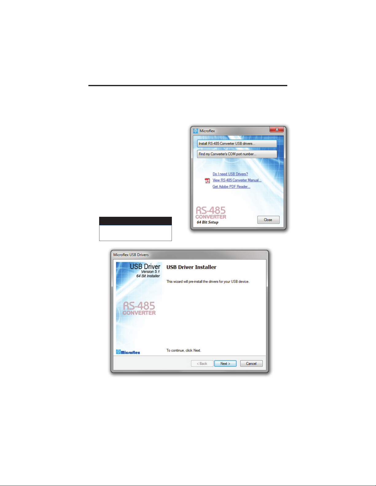
To pre-install the drivers, run
Setup.exe from the included CD and
follow the on-screen prompts. The CD
will auto-run this fi le if the Windows
Autorun feature is enabled for your CD
drive. The setup.exe is a utility that
will determine your operating system
and run the correct installer. Click the
Install RS-485 Converter USB drivers...
button to pre-install the drivers. The
driver installer will guide you through
the setup process.
Installers can also be run manually from the CD using \x86\DPInstx86.exe for 32
bit operating systems or x\64\DPInstx64.exe for 64 bit operating systems.
2
RS-485 Convert Setup Utility
Run the setup utility before
connecting to the USB port.
Important!
3
Driver - Manually Installed
To manually install the driver...
1. Connect the Converter to the USB port.
2. Open the Windows Device Manager.
3. The new device wizard will have added the converter under Ports (COM &
LPT) and will appear as USB RS485 Serial Converter (COMx). Right click the
device and select Update Driver Software...
4. Choose to Browse for the driver software and browse to the CD or the loca-
tion of the Mfl ex485.inf fi le.
5. Follow the wizard prompts to complete the driver setup.
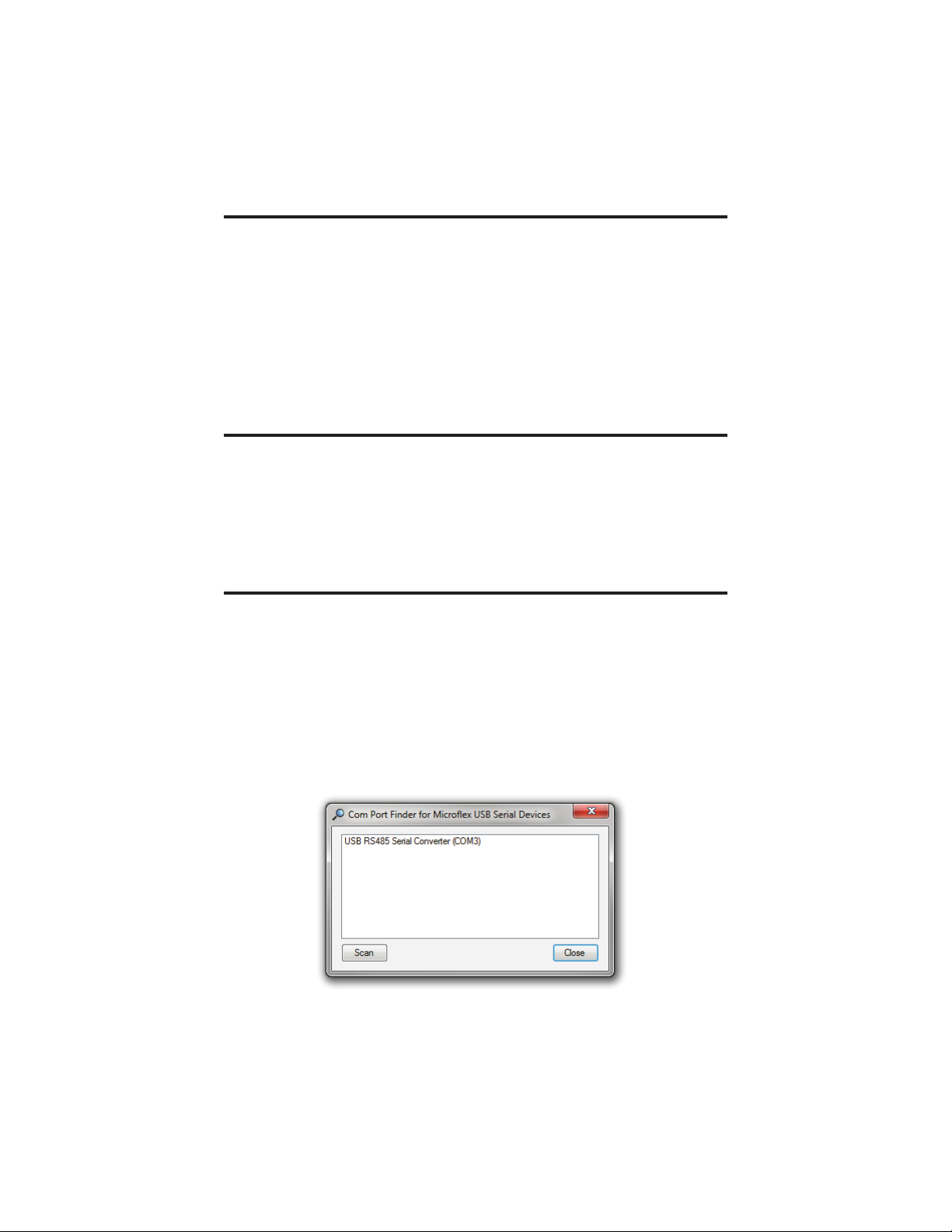
Finding the Assigned COM Port Number
When Windows installed the serial port emulator driver the next available
COM port number was assigned to the converter. The software you use with the
converter must be set to use the same COM port number. To fi nd the number as-
signed to your converter run the setup utility from the CD and click
Find my Converter’s COM port number...
The assigned COM port number can also be found using the Windows Device
Manager. You may need to expand the Device Manager tree under
Ports (COM and LPT) to see the converter.
Uninstalling the USB Driver
Use the Windows Device Manager to uninstall the driver from your system.
With the RS-485 Converter connected to your USB port, locate the RS-485
converter in the hardware tree. For details on how to do this refer to the section
on Changing the COM Port Number in this manual. Right click on USB RS485
Serial Converter and select Uninstall from the pop-up menu. When the process
has fi nished, unplug the converter from the USB port.
COM Port number finder. This converter is assigned to COM 3.

4
Changing the COM Port Number
The assigned serial COM port number can be changed to any available COM
port by using the Device Manager. Open the Device Manager and select
View > Devices by Type. Expand Ports (COM & LPT) in the list to see which port
the converter is assigned to. In the example shown below, the converter is as-
signed to COM3.
Right click on USB RS485 Serial Converter and select Properties from the pop-up
menu.
On the Port Settings tab, click Advanced. Drop down the COM Port Number list
and select the desired port number. Click OK to use the new port number and
close the window.
Click OK again to close the Properties window.
Windows Device Manager.
5
Software Setup
Make sure your software is set to use the same serial COM port that the RS-
485 converter was assigned. Refer to Finding the Assigned COM Port Number
and Changing the COM Port Number in this manual for details. There are no
hardware settings required by the RS-485 Converter and power is provided by
the USB port. All other settings, such as BAUD rate, are taken care of by your
software. The converter automatically switches between transmit and receive so
RTS is not required.
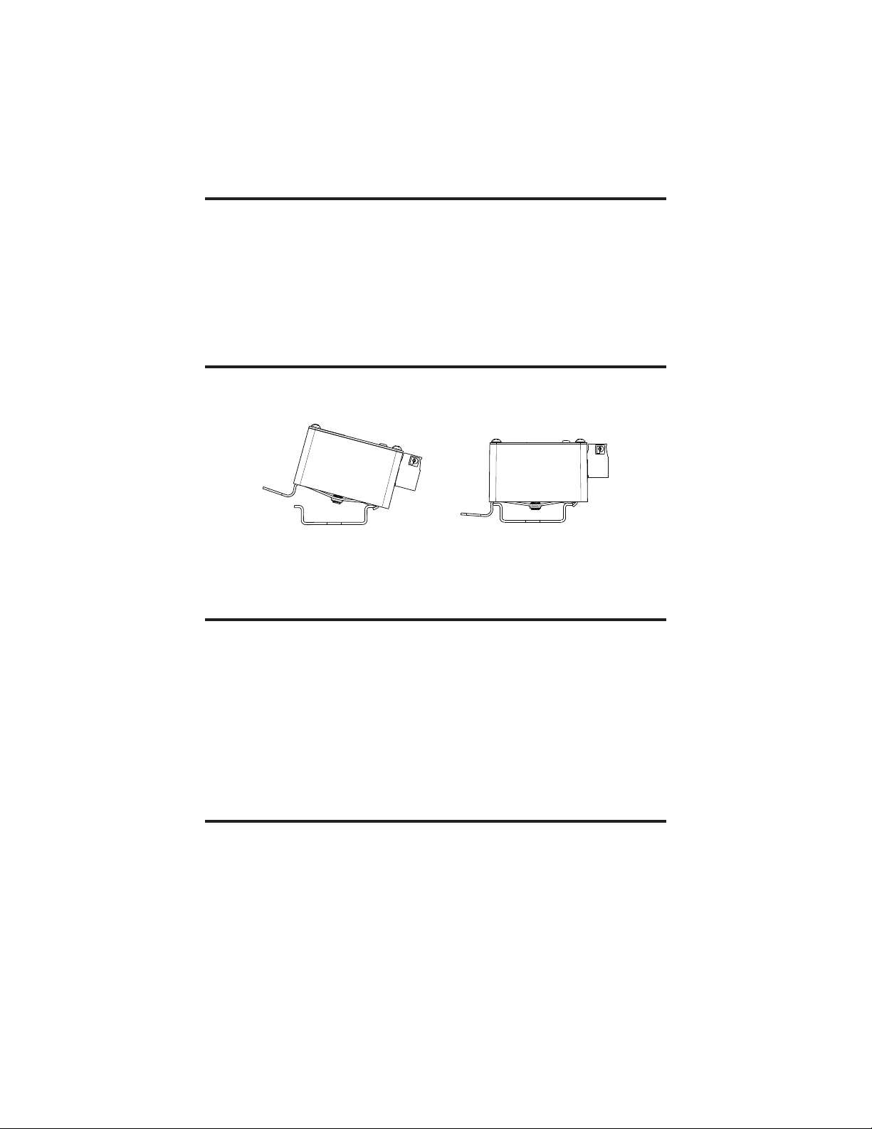
DIN Rail Mounting
The converter is designed to mount on standard 35mm DIN rail. It can be easily
snapped on and off the DIN rail without the need for any tools.
Lift up on the release lever to un-snap the converter from the rail.
Connecting to the RS-485 Bus
Connect the converter to the RS-485 bus using the A, B, and G. Connect the
G terminal to the RS-485 bus ground or shield. The G ground is galvonically
isolated from the converters USB ground. A and B are the noninverting and
inverting RS-485 transceivers.
The converter does not inlcude an internal bus terminating resister. RS-485 bus-
ses typically require a terminating resister at each end of the bus. Connecting di-
rectly to a device, to perform a confi guration for example, may be done without
a terminating resistor.
Status LED
When the converter is connected to a USB port the LED will be green after
the USB enumeration process completes and the USB drivers have sucessfully
initialized. A green LED indicates that the converter is ready to receive or is
receiving.
The LED will be red while the converter is transmitting RS-485 data.
35mm DIN Rail
Release Lever
Conformity in accordance with Part 2, and Part 15, Subparts A and B of
the Federal Communications Rules and Regulations, and ICES-003 of the
Industry Canada standards.
This device complies with part 15 of the FCC rules. Operation is subject
to the following two conditions: (1) This device may not cause harmful
interference, and (2) this device must accept any interference received,
including interference that may cause undesired operation. Changes or
modifications not expressly approved by Microflex, LLC could void the
user’s authority to operate this equipment.
Emissions EN55022: 1998
Electrostatic Discharge EN61000-4-2: 1995, A1: 1998, A2: 2001
Radiated Immunity EN 61000-4-3: 2002
Safety Compliance EN 60950-1: 2002
This device does not have protection from over-voltages which may exist
on USB ports of computers and relies on the protection existing in a host
computer.
This device is not intended for connection to the phone line through the
appropriate converters and shall not be connected to telecommunication
lines because it has no protection against over-voltages which may exist in
these lines.
The user shall ensure the protection of the operator from access to areas
with hazardous voltages or hazardous energy in their equipment.
The user shall ensure that the connection port of the field device and the
converter is separated at least by basic insulation from any primary circuit
existing in the field device.
Safety Considerations
6
PP
PP
PP
PP
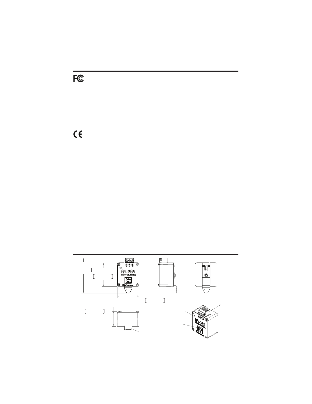
PP',15$,/&/,3
67$786/('
86%%
56
Dimensions

7
Specifications
Enclosure
Polycarbonate plastic and Stainless Steel Cover
Weight .................................................................................................5 ounces
USB
Connector .............................................................................................. USB-B
Compatibility ............................................................ USB 1.1, USB 2.0, USB 3
Active Current .................................................................................. 35mA Max
Suspend Current ........................................................ Less than 600μA Typical
RS-485
Termination ......................................... Plugable Screw Terminals, 26-12 AWG
G = Isolated ground, A = Non-inverting, B = Inverting
BUAD Rates ........... 300, 600, 1200, 2400, 4800, 9600, 14400, 19200, 38400
19200, 38400, 57600, 115200
Parity ............................................................... None, Odd, Even, Space, Mark
Driver Output Voltage ................................................................... Unloaded 5V
@ 27Ω Load 1.5V Min
Δ Input Threshold Receive Voltage ...................................................... +/- 0.2V
Receiver Input Hysteresis ............................................................... 25 mV Typ.
Receiver Input Resistance ................................................ > 96KΩ,125KΩ Typ.
Galvanic Isolation ..............................................................................2500VRMS
Surge Protection ......................................... 600W Silicone Avalanche Diodes
• Does not include RS-485 termination resistor
• Auto transmit control - RTS is not needed
• Power Up/Down glitch-free permits live insertion or removal
• High common mode transient immunity: 30kv/us
• 2500VRMS Galvanic isolation
• 7-bit no parity mode requires 2 stop bits
Status LED
Green ................................................ USB Enumerated and ready / Receiving
Red ............................................................................................... Transmitting
Mounting
Snaps on and off standard 35mm DIN rail, no tools needed
Environmental
Operating Temperature ...................................... -20ºC to 50ºC (-4ºF to 122ºF)
Storage Temperature ....................................... -40ºC to 85ºC (-40ºF to 185ºF)
Humidity .................................................................0 to 99% (non-condensing)

Limited Warranty
Microfl ex, LLC warrants this unit against defects in materials and workmanship for a
period of one year from the date of shipment. Microfl ex, LLC will, at its option, repair or
replace equipment that proves to be defective during the warranty period. This warranty
includes parts and labor.
A Return Materials Authorization (RMA) number must be obtained from the factory
and clearly marked on the outside of the package before equipment will be accepted for
warranty work.
Microfl ex, LLC believes that the information in this manual is accurate. In the event that
a typographical or technical error exist, Microfl ex, LLC reserves the right to make changes
without prior notice to holders of this edition. The reader should consult Microfl ex, LLC
if any errors are suspected. In no event should Microfl ex, LLC be liable for any damages
arising out of or related to this document or the information contained in it.
EXCEPT AS SPECIFIED HEREIN, MICROFLEX, LLC MAKES NO WARRANTIES OR
MERCHANTABILITY OR FITNESS FOR A PARTICULAR PURPOSE. CUSTOMER’S
RIGHT TO RECOVER DAMAGES CAUSED BY FAULT OR NEGLIGENCE ON THE
PART OF MICROFLEX SHALL BE LIMITED TO THE AMOUNT THERETOFORE
PAID BY THE CUSTOMER. MICROFLEX, LLC WILL NOT BE LIABLE FOR
DAMAGES RESULTING FROM LOSS OF DATA, PROFITS, USE OF PRODUCTS,
OR INCIDENTAL OR CONSEQUENTIAL DAMAGES, EVEN IF ADVISED OF THE
POSSIBILITIES THEREOF. This limitation of the liability of Microfl ex, LLC will apply
regardless of the form of action, whether in contract or tort, including negligence. Any
action against Microfl ex, LLC must be brought within one year after the cause of action
accrues. The warranty provided herein does not cover damages, defects, malfunctions, or
service failures caused by owners failure to follow Microfl ex, LLC’s installation, operation,
or maintenance instructions; owners modifi cation of the product; owner’s abuse, misuse, or
negligent acts; and power failure or surges, fi re, fl ood, accident, actions of third parties, or
other events outside reasonable control.
Microflex, LLC
35900 Royal Road
Pattison, Texas 77423
USA
The HART protocol is supported by the HART Communications Foundation in Austin Texas,
www.hartcomm.org. HART is a registered trademark of the HART Communications Foundation.
Phone 281-855-9639
Fax 832-422-4391
www.microflx.com
Table of contents
Other Microflex Media Converter manuals


Popular Media Converter manuals by other brands


Lika
Lika Rotapuls C58 quick start guide

Antelope
Antelope Zodiac Platinum DSD256 owner's manual

PS Audio
PS Audio Stellar Gain Cell DAC Instructions for use

PR electronics
PR electronics 3100 Series product manual

evertz
evertz 7735CEM manual

Moxa Technologies
Moxa Technologies NPort 5600-8-DT Quick installation guide

Danfoss
Danfoss IP21/Type 1 Conversion Kit installation instructions

Steren
Steren ELI-030 user manual

Absolute Process Instruments
Absolute Process Instruments DuoPak APD 2050 manual

Focusrite
Focusrite MIXMASTER Platinum Digital Option installation guide

MRC
MRC 0001628 quick start guide

TR-Electronic
TR-Electronic CRW582M 8192 CO+CO SLG ME 5M Series Assembly instructions