Microgreen Power Pak User manual

Power Pak Installation Manual
Version 3

Power Pak Parts

Power Pak Installation procedure
Make sure that all the breakers and battery switch on the Power Pak are turned off.
Read the entire installation manual before starting. It will give you a better
perspective about the mechanics of the installation.
We also recommend you should have another person to help you during this
installation.
The Power Pak unit should be installed near your electrical panel. Mount the Power Pak at least 4 to 5 feet off
the floor, allowing room to access to the lower AC in and AC out terminal connections. Make room on the floor
to ho u s e the batteries.
The Power Pak has two flat rails that it rests upon and are to be used when mounting it on t h e w a l l .See above
Figure 1
Each rail has 3 elongated holes, along with 6 round holes giving you multiple spots to screw into the wall.
Due to the weight of the Power Pak, we recommended the Power Pak be mounted on at least one stud.
Mount a piece of plywood on the wall fo r the Power Pak to installed upon.
At least two of theh o le s o n t h e rails, areat the distance of two studs.Mounting the Power Pak across 2 studs is
preferred.
Using a #12 pan head wood screw at 2 “ long, add a ¼ washer under the head of the screw. Proceed to drill the
screw into the top centre hole while holding the unit in place.
If you do not have a helper to hold the unit, mount a 2 X 2 or 2 X 4 with screws, on the wall. L e v el this wooden
brace, it will make it easier to install the Power Pak.
Rest the Power Pak on this wooden support and install it. ( if you level the wooden support first, then you can
mount all 3 screws into the top rail)finish by mounting the bottom three screws. Otherwise mount one screw
on top rail and move the unit until it is level and mount a second screw.

Batteries
The battery switch located on the side of the Power Pak must be in the off position. This protects the inverter
from any sparks that may cause a voltage jump, when connecting the battery leads to the inverter. There is a
potential voltage difference between the batteries and the inverter. The capacitors inside the inverter need to
be brought up to the same potential as the batteries. This will occur when you turn the battery switch on later.
When installing the batteries, they should be located below the Power Pak. If the are being placed on concrete
floor, place a 2 “piece of Styrofoam under the batteries. The Batteries should not be made cold by the concrete
floor.
A concrete floor will make the Batteries cold, which will affect their operation. If the Batteries are as cold as 0
degrees Celsius, the Battery may appear to be full, but can only deliver 50 % of it’s power.
The Power Pak comes two temperature probes. One for the Inverter and one for the Charge Controller, they
each have a specific plug on the side of the Power Pak. Connect the other end of the sensor between the
batteries.
The colder the Batteries get the higher the charging voltage will go. this is important if the charge controller is
left on during the winter.
D O N OT let the black and red cable ends touch each other, they will produce a large spark, which could
damage the new batteries
Connect a minimum of,2 – 12-vo lt batteries or 4 – 6-volt batteries together to energize the Power Pak.
.Seebelow Figure 2-3
The Power Pak operates from a 24 Volt DC supply. You can connect more 24-voltbattery groups together. Each
pair of batteries is considered a group. There is a limit of up to 5 groups of batteries can be connected to this
unit. When installing two groups together, connect across the neg to neg and then across the pos to pos. Place
the inverter cables across the two groups in order to get an equal charge in all cells.See below Figure 2
If you install 3 to 5 groups of batteries, you should use two bus bars, one for positive and one for negative.See
Figure 3
This method of mounting interconnect cables will insure each battery receives the same amount of charge.
You will need to buy a proper bus bar or use a piece of copper bar, ¼” thick 1.5 “ wide and 6 inches long.
Then drill the bus bar with 6 holes of 3/8” diameter each and spaced evenly across the bus bar.
Drill some smaller holes ( 1/8 inch dia) in the 4 corners for mounting the bus bar on the back wall.
You will need longer interconnect cables for this bus b a r installation.
Take a cable from each negative pole of each battery and connect it to the negative bus bar.
Repeat for the positive side. The battery leads to the Power Pak should not be any longer than 10 feet or 3
metres
Microgreen can supply premanufacturedbus bars and longer interconnect cables as required.See fig 3

Once all the interconnect cables ( cables used to group the batteries together) are connected, verify with a
meter that your system voltage is 24 volts DC.M easure across the Positive and Negative poles of the battery
group.,
Measure across the batteries where the battery cable from the inverter will connect. Once the battery voltage
is verified, connect the black ( negative) cable from the bus bar to the inverter.
Then connect the red, Positive cable to the inverter from the other bus bar. C h e ck t h a t al l connections are tight.
Make sure polarity is kept right for each step of the installation.
Once all the batteries are installed, supported and connected, turn the battery cable switch to ON. The DC
meter on the front panel should come ON and show your battery voltage level.
Once the battery cables are all installed, you must build a protective cover over the two bus bars, IE plywood
door.You Do Notwant any metal object fall across these bus bars.
Selecting Battery type
There is a selector switch beside the On/Off switch. Choose 1 for Gel, 2 for AGM and 4 for flooded.
In section 2.5.2 of the manual has a full explanation of your choices

Main System
Operational Section
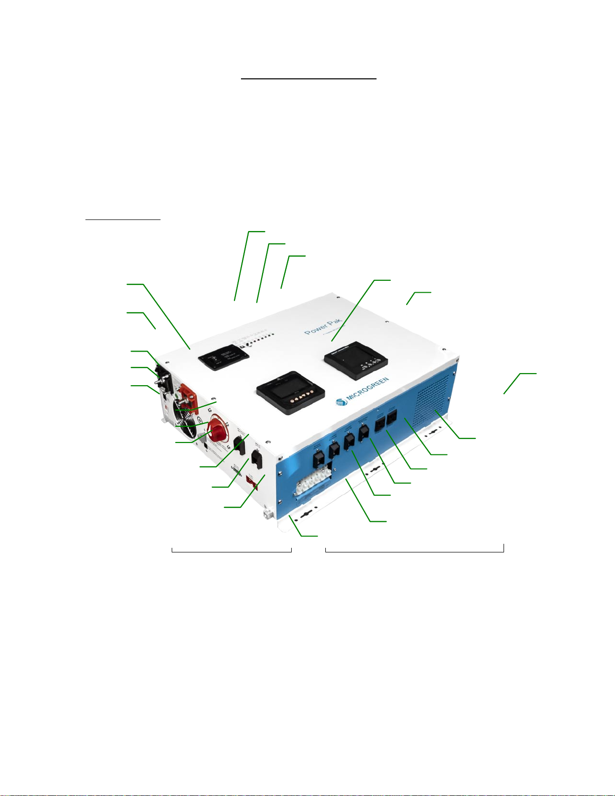
Push the Power Pak switch “ ON” ( push it down)to activate the unit. See fi g 1
Once the unit has gone through its initial power up routine a green LED will turn on to show the unit is ready
and operating ( LED is on the front panel beside the power ON switch ( see Figure 1)
The front panel AC meter should come on, after 5 seconds and show an A C output voltage of around 120 AC
volts. Should it not come on, verify the AC output breaker, located on the bottom of the Power Pak is in the ON
position.
This Power Pak has a 120/240 split phase AC output. This means there is a L1and L2 output with a neutral.
Two- line voltages of 120 AC on the AC meter will appear.
This AC meter will show your instantaneous watts( what is actually operating at that moment) being consumed
and the total watts used over a period of time,(IE: a weekend). This meter allows you toreset the total Kw/hr
reading.C h e c k t h e appendix of th e Power Pak manual on how to reset the total Kw reading.
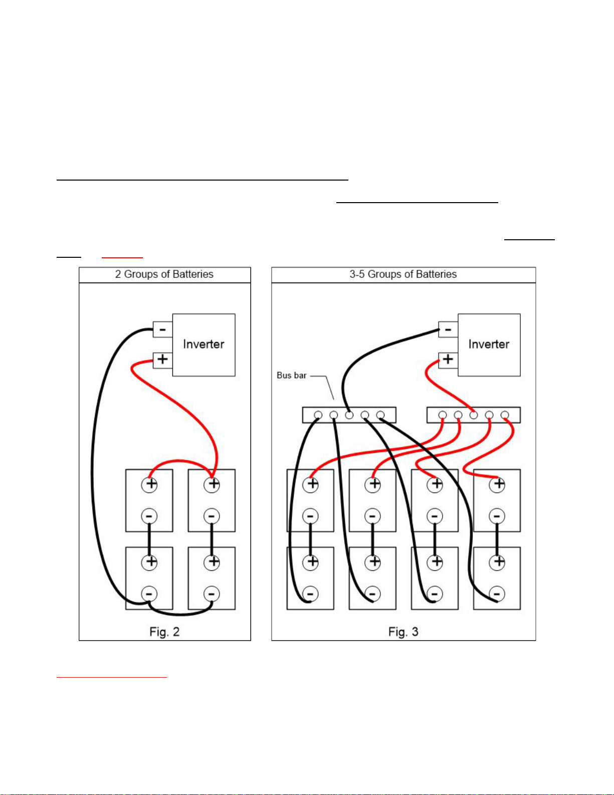
To understand how much power is available to use, check the following information., In a 24-volt system, using
4-12 volt Batteries, two in series and 4 in parallel@ 105 amp/hr, means2 batteries groupswill be (105 times2
times 24 V, equals about 5000 watts) You would have about 2500 watts of usable power ( 50% of the batteries
total). IF you have 4 – 6 volt @ 400 amp/hr batteries, the power available is as follows. 400 times 24 volts
equals 9600 watts, ( 50% of this will be 4800 watts of usable power)
Therefore, based on how many watts you may consume on a weekend, will s h o w , if t h e battery bank ise n o u g h .
When considering on whether to use 12 volt or 6 volt batteries, keep in mind to amount of power you may
want eventually. If you choose 12 volt batteries, the maximum amount of power you can connect is 5 groups of
100 amp/hr or 24 times 500 equals 12,000 watts of power of which 50% is usable.
If you chose 6 volt, you can have 5 groups of 4-6 volt batteries or 50,000 watts available with 50% usable.
You can not mix 12 volt and 6 volt batteries.
Verify the status of your batteries,by re ading their value first thing in the morning. The battery is a current
device; therefore, your voltage swing in the battery is from 24 volts to 25.6 for 50% of the batte ry’s capacity.
Any number above 25.6 is an arbitrary number as a result after the charging cycle.
When you check the voltage level first thing in the morning before the sun has hit the panels and no major load
is operating, you can see present status. Determ ine the level of your batteries by the voltage level.
( 24 volts is 50 %, 24.8 is 75 % and 25.6 is 100 %.) after charging orrestingovernight.
If you check the voltage level during the day, it will be misleadingv a l u e , due to the solar power coming in, and
power being drawn out.
Since you are actively using power during the day, the voltage level does not properly represent to true value of
the batteries. If you checked the voltage level just after you had vacuumed, the level would be artificially low.
You just removed a lot of current out of the batteries, so they will appear low. Give t h em 10 minutes and check

the level again. You will see a totally different story. The battery level is no w closer to the real value. The value
will settle down within the first 10 minutes after a great current draw.
If the Battery voltage is 24 volts or lower in the morning, charge the Batteries immediately. The battery level
should not go below 24 Volts or 50%, to often, this will cause them to prematurely age.
PowerSaver, to activate this feature. Push the on switch upward passed the center off section.
The Power Pak uses approx. 1000 wats a day as overhead. To minimize this draw , you can use the power saver
feature.
If you have a constant draw like a fridge with a defrost clock, power saver wil not work. The Power Pak will
always be on. Make sure you have enough batteries and panels to compensate for this situation. ( IE 4 - 60 cell
Solar panels and at least 4 - 6 volt 400 amp/hr batteries
The Power Pak will turn off except for a small pulse every 3 seconds. This pulse is looking for any equipment
that wants to turn on.
If the item is large enough in watts consumption( approx. 40 watts), it will activate the inverter to turn on.
Otherwise the inverter sits in idle mode consuming almost no power. If used properly, this feature could save
you about 800 watts a day.
It takes about 40 watts to activate the Power Pak to turn on.
When using Power Saver, normal appliances like a fridge will always turn on when required and turn off. To
activate the inverter just turn on a large enough load and it will keep the inverter operating as long as you need
it. Then turn off this item and the unit goes back into power saver mode.
AC wiring, switch off the Power Pak for this section
Please refer to your local rules or guidelines for what is allowed or not when connecting to the electrical panel.
Wiring the AC input and AC output from the Power Pak is done through the white AC terminal strip located on
the lower left side of the unit. All the AC power goes through this terminal strip. AC output should be connected
to your electrical panel. Use a 3 conductor 8 gauge wire to run from Power Pak to the Electrical panel. There are
L1 and L2 plus a neutral. The L1 and L2 ( Red and Black) are to be connected to a 50 amp double breaker. The
neutral ( white)should be connected to the neutral buss bar beside the breakers.
The AC input should come from your external power source and used to charge the batteries. There is only a L1
and L2 ( 240 volt only, input is required for charging the batteries)The terminal strip is labeled accordingly.
There are two AC outlets on the bottom side of the Power Pak. When the Power Pak is operating, there is up to
20 amps of AC power @, 120 Volts are available in each receptacle. At this point power is accessible, without
connecting the AC output of the Power Pak to the electrical panel.
When connecting to the AC terminal strip on the side of the unit, only undo the front screw.
The inner screw holds the inside wire from the Inverter to the terminal strip.

Charging the Batteries
The AC input is for your back up device, whether the Grid or a generator. This needs to be connected to the
electrical panelfor the grid. When the generator or grid supply’s the AC input to the Power Pak s h o u l d s w it ch to
chargingwithin a minute, if the batteries are low enough.
A yel low LED on the front panel will turn on, showing you the Power Pak is in charge mode.
When the Power Pak is in charge mode, it is feeding the loads connected at that time. Do not do laundry or use
a high load appliance. You will delay how long it will take to charge the batteries.
The power Pak also has an AGS feature( auto genstart signal). This signal can be used to auto-start your
generator if the batteries go too low.Depending upon the make and style of the back-up generator, an interface
device will be neededfor the Power Pak to auto-start the generator.Contact Microgreen and they can assist
you with this.
If the battery voltage is not low enough for the Power Pak to automatically switch into charge mode, turn off
the Power Pak while the AC input is live, t h e n turn the Power Pak back on, The Power Pak will switch into
charge mode, within 1 minute. ( t h e P o wer Pak needs a stable AC input before switching to charge mode)
Installing the solar panels
The built in Charge controller can handle a maximum of 150 volt DC input and 40 amps, therefore you
connect up to 1000 watts to the controller ( if slightly more, controller will only take the 1000 watts)
Firstly, their location must be chosen. Panels should face South or if required, they can face SE or SW.
Are they going to be ground mounted or on a roof? Then, the type of mounting hardware needs to be
chosen, based upon their location. Microgreen has mounting hardware.
If you mount the Panels on your roof, you will need to install a rapid shut down and an arc fault device
to protect the fireman who may be attending a fire at your home. These are not a cheap item.
When connectingtwo panels, connect the wires in series(for every two panels). The plugs on the panels are
keyed, to minimize hooking them up incorrectly.
Connect the positive ( + ) of one panel to the (-) of the other panel. Run the other two wires down to the
connections on the power pack. When using 4 panels, repeat this process again. When using 4 panels connect
two of each pair in series, then connect the two pairs in parallel.to do this, connect 2 positive wires and
connect 2 negative wires. Using a 2:1 combiner connector, connect the 2 red into one combiner and the 2 black
wires together into the o t h e r . Bring these two wires down to the power Pak. (You can connect up to a
maximum of three panels in series. Never connect 4 in series, you will exceed the controller 150-volt limit.)
Plug the Anderson connector to these two MC4 w ires coming in from the panels.
Make sure the polarity is correct by verifying the position from each off the labelling on the side of the Power
Pak
Measure the polarityis correct before connecting these two wires to the Power Pak.

If the DC meter shows 0 volts and 0 amps on the bottom left side, after connecting the panels, they may be
connected backwards.
This does not damage the panels, just switch the Pos and Neg wires around and re connect.
Measure the voltage from the two wires coming from the panels. The red should be positive and show
approximately40-60 v o lts
If it is cloudy,themeasurementwill drop to around 20 to 50 volts.
The solar input of the DC meter will activatewhen you plug in the Solar connector ( verify the DC input breaker
is on), You should see a voltage and current reading ( amps).
Multiple the volts times amps on the display to see how many watts are coming in from the panels.
Turn on the front panel switch again, you will see the AC meter a c tiv ate and the system is ready for use.
Ground wire
The system comes with bare Ground wire and a ground plate if required. If you have an existing ground for
your existing electrical panel, do not install a second ground. ESA does not allow two ground plates unless one
is under another building at least 100 feet away. This could create a ground loop.
If there is an existing ground system in the building, you will need to take the ground wire connected to the
Power Pak and bond ( crimp ) it to the existing ground wire near the existing electrical panel.
If there is no existing ground for the building, install the ground plate outside in the ground below the Power
Pak. The ground wire is only 20 feet lo n g.
Dig a hole 1.5 feet deep. Place the ground plate horizontally in the hole.
Attach the bare ground wire to the ground plate with the brass lug at one end of the ground plate. Fill in and
tamper the dirt over the ground plate. Run the ground wire up to the Power Pak and connect it to the
grounding terminal on the base of the Power Pak just below the solar breakers.
Other manuals for Power Pak
1
Table of contents
Other Microgreen Inverter manuals
Popular Inverter manuals by other brands

Victron energy
Victron energy BlueSolar Series manual

Leroy-Somer
Leroy-Somer DIGIDRIVE Series Installation and commissioning

MPP Solar
MPP Solar PIP3624MT user manual

Eltek Valere
Eltek Valere PWS Series user manual

aci
aci SUN SHIELD HUMIDITY Series Installation & operation instructions

Northern Lights
Northern Lights Lugger OM944W Operator's manual