Microgreen Power Pak User manual

Microgreen.ca
Power Pak user manual
Off-Grid System
In a Box
3kW / 4kW / 10kW Models

1

2
Table of Contents
1HOW TO USE THIS MANUAL ...............................................................................................................................................................................4
2POWER PAK MODELS.............................................................................................................................................................................................4
3SYSTEM OVERVIEW .................................................................................................................................................................................................. 7
4PRODUCT DESCRIPTION.......................................................................................................................................................................................8
4.1 Recommended Uses................................................................................................................................................................................... 9
4.2 Features............................................................................................................................................................................................................. 10
5IMPORTANT SAFETY INFORMATION..............................................................................................................................................................11
5.1 General safety precautions......................................................................................................................................................................11
5.2 Precautions When Working with Batteries.................................................................................................................................12
6INSTALLATION.............................................................................................................................................................................................................13
6.1 Components Not included .....................................................................................................................................................................13
6.2 Tools required.................................................................................................................................................................................................13
6.3 Wall Mounting............................................................................................................................................................................................... 14
6.4 Battery Connection.................................................................................................................................................................................... 14
6.5 Solar Panels Connection (optional)...................................................................................................................................................15
6.6 Expanding the System: Additional Charge Controllers & Wind Turbines (Optional).........................................15
6.7 Grounding.........................................................................................................................................................................................................16
6.8 AC Connections - Input and Output (Optional).........................................................................................................................17
6.8.1 AC Input Connections:.........................................................................................................................................................................17
6.8.2 AC Output Connections:.................................................................................................................................................................... 18
7OPERATING INSTRUCTIONS............................................................................................................................................................................. 20
7.1 General Operating Instructions......................................................................................................................................................... 20
7.1.1 Power Saver Mode................................................................................................................................................................................ 20
7.1.2 Charging Batteries............................................................................................................................................................................... 20
7.2 Monitoring ........................................................................................................................................................................................................21
7.2.1 AC Meter......................................................................................................................................................................................................22
7.2.1.1 Button Functions..............................................................................................................................................................................23
7.2.2 DC Meter......................................................................................................................................................................................................25

3
8COMPONENTS DESCRIPTION AND FEATURES.................................................................................................................................... 28
8.1 Topology........................................................................................................................................................................................................... 28
8.2 Charging .......................................................................................................................................................................................................... 28
8.2.1 Battery Type Selector ......................................................................................................................................................................... 30
8.2.2 De-Sulphation......................................................................................................................................................................................... 30
8.2.3 Charging Depleted Batteries...........................................................................................................................................................31
8.2.4 Charging Current & Tips for Charging from a Generator...............................................................................................31
8.3 Power Transfer..............................................................................................................................................................................................32
8.4 Alarms & Protections.................................................................................................................................................................................32
8.5 LED Indicators ...............................................................................................................................................................................................33
8.6 Fans..................................................................................................................................................................................................................... 34
8.7 DIP Switches.................................................................................................................................................................................................. 34
8.8 Other Features..............................................................................................................................................................................................36
8.8.1 Battery Voltage Recover Start .......................................................................................................................................................36
8.8.2 Auto Gen Start .........................................................................................................................................................................................36
9TROUBLESHOOTING GUIDE..............................................................................................................................................................................37
10 WARRANTY..............................................................................................................................................................................................................39
11 POWER PAK SPECS SHEET...............................................................................................................................................................................40
12 HOW TO CONTACT US...................................................................................................................................................................................... 41

4
1How to use this manual
This manual contains important information about how to install and operate your Power Pak. Before
installing, please thoroughly read the Important Safety Information section and the Installation section. Please
also read the Operating Instructions section before beginning to use the Power Pak.
The section entitled Components Description and Features contains detailed technical information that may
not be of interest to most users. However, these technical details may be helpful if any troubleshooting is
required.
This manual also includes a troubleshooting guide that provides recommended solutions to common
problems.
A product specifications sheet is provided at the end of this manual, in Appendix 1.
This warning symbol appears throughout this manual. These warnings alert the reader that a
particular action, or inaction, may result in damage to the Power Pak, damage to surrounding
property, and/or risk of injury or death. These warnings must be heeded when installing or operating the
Power Pak.
2Power Pak Models
This manual covers the 3 available Power Pak Models. The features and functionalities are largely the same,
the main differences being the AC power output rating, the battery voltage required, and the maximum
charge that can be accepted from solar panels:
Power Pak MINI
Power Pak COMPACT
Power Pak GRANDE
3 KW max. output
120V AC and 12 V DC output
Uses 12 V battery
Max. 500 W solar input
4 KW max. output
120/240 V AC output
Uses 24 V battery
Max. 1000 W solar input
10 KW max. output
120/240 V AC output
Uses 48 V battery
Max. 4000 W solar input

5
MINI Power Pak
COMPACT Power Pak

6
GRANDE Power Pak

7
3System Overview
The Power Pak is designed to be the central piece in a solar powered energy system. Its flexible design allows
it to be used in a number of configurations:
1. Solar-powered off-grid system - combined with solar panels, and batteries (for energy storage) to
provide power for your household. No grid connection or generator is required.
2. Hybrid system - solar power to be used as the primary energy source, with grid power available as a
back-up.
3. Hybrid system with no grid connection - solar power as the primary energy source, with a connected
generator available as a back-up.
4. Multi-source off-grid system - solar power to be used as the primary energy source, with a secondary
source available to charge the energy storage in parallel (such as a wind turbine).
5. Back-up power system - grid power to be used as the primary energy source, with the Power Pak and
energy storage (with or without solar) available as a back-up in the event of a power outage.
Note: The Power Pak does NOT work as an “on-grid” system, where solar energy can be fed back to the grid
for credit.
Before installing the Power Pak, please take a few moments to understand how it fits into your power system.
The Power Pak is ULc certified. Please make sure that you understand all the safety precautions (see section
5).

8
4Product Description

9
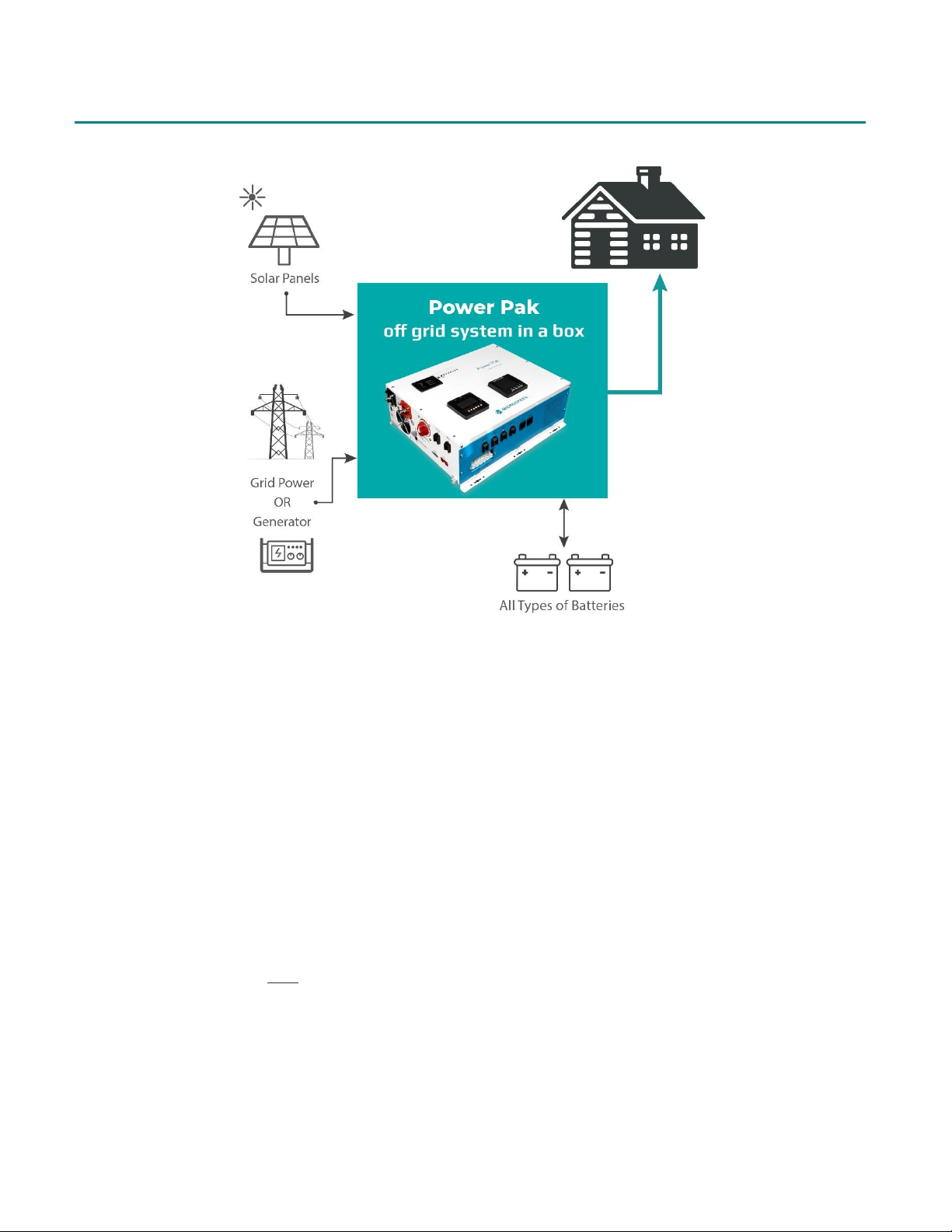
The Power Pak combines an inverter, AC auto-transfer switch, battery charger, and solar charge controller
into one complete system with a peak overall conversion efficiency of 80% to 85%, with an inverter efficiency
of 95%. It features power factor corrected, sophisticated multi-stage charging and pure sine wave output with
unprecedented high surge capability to meet the demanding power needs of inductive loads without
damaging the equipment.
It works by converting power from solar panels to power home appliances. Excess power is used to charge a
battery bank, which can be used during periods of low sunlight.
The Power Pak can be optionally set up as a back-up power source for the grid or generator. This can be done
by connecting it to an AC power source - either the electrical grid or a generator - and by setting it to AC
Utility Priority Mode. When connected to the AC source, the batteries can be maintained at a high state of
charge and can act as a backup power source. When utility AC power cuts out or falls below a certain
threshold, an auto transfer switch automatically transfers the load to the Power Pak’s output. Once the AC
utility power is restored, and the load is automatically reconnected to AC utility power.
The Power Pak’s settings can alternatively be configured to prioritize power usage from the battery over
power from AC sources. This helps to extract maximum power from the battery in renewable energy systems.
This is achieved by setting the Power Pak to Solar Priority mode.
For optimal performance the Power Pak must be installed and operated properly. Please read the instructions
in this manual before installing and operating the Power Pak. Also refer to the Power Pak Installation Manual
for additional details for battery and solar panel connections.
The Power Pak is fully certified to the UL standard and to the CSA standard, thus meeting rigorous safety and
quality standards. All individual components, connections, and meters as well as the unit as a whole are thus
UL certified.
The Power Pak does not require any routine maintenance. Associated system components, such as batteries,
solar panels or generators, may require maintenance and their respective user manuals should be consulted.
4.1 Recommended Uses
The Power Pak is suitable for renewable energy systems, grid powered systems, RVs, cabins, marine
applications and emergency appliances. Below are some examples of the types of appliances that can be used
with the Power Pak.
▪Power tools –circular saws, drills, grinders, sanders, buffers, hedge trimmers, air compressors.
▪Office equipment –computers, printers, monitors, fax machines, scanners.
▪Household items –vacuum cleaners, fans, fluorescent and incandescent lights, shavers, sewing
▪machines.
▪Kitchen appliances –coffee makers, blenders, ice markers, toasters.

10
▪Industrial equipment –metal halide lamps, high-pressure sodium lamps.
▪Home entertainment electronics –TVs, VCRs, video games, stereos, musical instruments, satellite
equipment.
4.2 Features
•Easy to install & operate
•ULc certified for safest possible operation
•Designed to operate in harsh environments
•Compatible with both linear & non-linear loads
•Separate 15A fused AC output receptacles
•Low DC voltage supports home & office appliances (3kW model only)
•DC start & automatic self-diagnostic function
•AC charging (from grid/generator) and DC charging (from solar panels) available
•Powerful battery charge current, selectable from 20% - 100%
•High efficiency design & PowerSaver mode to conserve energy
•Battery priority mode to designate the UPS configuration
•Battery recover point, dedicated for renewable energy systems: 11.5 VDC (MINI), 21 VDC (COMPACT), 42
VDC (GRANDE)
•8 pre-set battery type selector, plus de-sulphation (for flooded lead acid batteries)
•4-step intelligent battery charging with power factor correction
•8ms typical transfer time between utility & battery to ensure power continuity
•15s delay before transfer when AC resumes to protect load when used with a generator
•Supports a wide range of batteries such as lead acid, AGM, deep-cycle, and lithium.

11
5Important Safety Information
WARNING
This manual contains important instructions for all Power Pak models that must be followed during
installation, operation and maintenance. Failure to follow these instructions may result in damage, fire, injury
or death.
5.1 General safety precautions
All components and connections of the Power Pak are ULc certified; however safety precautions must be
followed when handling any electrical equipment. Please read and understand the following section.
Do not expose the Power Pak to rain, snow, spray, bilge or dust. To reduce risk of hazard, do not cover or
obstruct the ventilation openings. Do not install the Power Pak in a zero-clearance compartment. Overheating
may result. Allow at least 30 cm (11.81 inches) of clearance around the Power Pak for air flow. Make sure that
the air can circulate freely around the unit.
To avoid a risk of fire and electronic shock. Make sure that existing wiring is in good electrical condition; and
that wires are not undersized. Do not operate the Power Pak with damaged or undersized wiring.
This equipment contains components which can produce electrical arcs or sparks. To prevent fire or explosion
do not install in compartments containing flammable materials or in locations which require ignition-
protected equipment. This includes any space containing gasoline-powered machinery, fuel tanks, or joints,
fittings, or other connection between components of a fuel system.
Do not disassemble the Power Pak. It contains no user serviceable parts and disassembly will void the
warranty. Attempting to service the Power Pak yourself may result in a risk of electrical shock or fire. Internal
capacitors remain charged after all power is disconnected. See Warranty for instructions on obtaining service.
To reduce the risk of electrical shock, disconnect both AC and DC power from the Power Pak before
attempting any maintenance or cleaning. Turning off controls will not reduce this risk.
CAUTION - Equipment damage:
The output side of the inverter’s AC wiring should at no time be connected to grid power or a generator. This
condition is far worse than a short circuit. If the unit survives this condition, it will shut down until corrections
are made.

12
Installation should ensure that the inverter’ s AC output is, at no time, connected to its AC input.
WARNING –LIMITATIONS ON USE
The Power Pak should not be used in connection with critical life support systems as it is not a
redundant power source.
5.2 Precautions When Working with Batteries
If battery acid contacts skin or clothing, wash immediately with soap and water. If acid contacts the eye,
immediately flush the eye with running cold water for at least 20 minutes and get medical attention
immediately.
Never smoke or allow a spark or flame in the vicinity of a battery or engine.
Do not drop a metal tool on the battery. The resulting spark or short-circuit may cause an explosion.
Remove metallic personal items such as rings, bracelets, necklaces, and watches when working with a battery.
A battery can produce a short-circuit current high enough to weld a ring or other metallic items, causing a
severe burn.
To reduce the risk of injury, charge only rechargeable batteries such as deep-cycle lead acid, lead antimony,
lead calcium gel cell, absorbed mat, NiCad/NiFe or lithium ion batteries. Other types of batteries may burst,
causing personal injury and/or damage.

13
6Installation
Follow all local regulations when installing the Power Pak.
It is recommended to have at least 2 persons present during installation.
The Power Pak should be installed indoors in a location that is dry, clean and cool. Leave at least 12 inches of
space around all sides of the Power Pak for ventilation. It is recommended to install the Power Pak near the
building’s electrical panel.
Working temperature: ‐10℃to 40℃
Storage temperature: ‐40 to 70℃
Relative Humidity: 0% to 95%, non-condensing
Installation can be completed in 3-4 easy steps:
1. Wall-mount the Power Pak
2. Install and connect the batteries
3. Install and connect the solar panels (optional)
4. Connect the Power Pak to the electrical panel (optional) and generator (optional)
6.1 Components Not included
The following components must be provided by the user:
•A plywood board –2 x 3 feet for the MINI or COMPACT models; 2.5 x 3.5 feet for the GRANDE model.
•#12 pan head wood screws (1” min.) for mounting the Power Pak on the plywood. Will require at least 6
screws for MINI or COMPACT; 8 screws required for the GRANDE.
•A set of hardware for mounting the plywood board to the wall
•Appropriate cable to connect to the electrical panel - 3-wire for MINI, 4-wire for COMPACT or GRANDE.
6.2 Tools required
●Drill or Power driver
●Screwdriver
●Multimeter
●Shovel (only if building does not have an existing electrical ground)

14
6.3 Wall Mounting
STEPS:
1. Securely mount a piece of plywood on the wall for the Power Pak to be installed upon.
2. Mount the Mounting Plate to the plywood. The Mounting Panel will support the weight of the Power
Pak so it must be secure. Use at least 3 #12 pan head wood screws (1” min.) on the mounting plate of
the MINI or COMPACT. Use at least 4 screws for the GRANDE.
3. Hook the bottom rail of the Power Pak onto the lip of the Mounting Panel. The Mounting Panel will
support the weight of the Power Pak. Use 3 screws in the top rail to secure the Power Pak to the wall.
6.4 Battery Connection
WARNING
Failure to follow these instructions may result in sparking and damage to the batteries.
•Before connecting the batteries, ensure the battery bank is configured to provide the correct
voltage for the specific Power Pak model being installed. See Appendix 1 for specifications.
•Do NOT let the black and red cable ends touch each other at any time. Ensure polarities are
connected correctly.
•Do NOT let any metal object fall across the terminals during the installation.
STEPS:
1. Make sure the Battery Switch [11] is off.
2. Place the batteries close to the Power Pak (less than 10 ft) to reduce the energy lost in the cable.
3. Connect one end of the temperature sensor to the Power Pak and place the other end next to the
batteries. The temperature of the batteries is used by the Power Pak to determine the correct
charging voltage. This is very important if the Power Pak is used in cold temperatures.
4. Set the battery type using the Battery Type Selector switch located beside the On/Off switch. Choose 1
for Gel, 2 for AGM and 4 for flooded. See Section 8.2.1 for a complete list of choices.
Failure to select the correct type may result in damage, fire or explosion.

15
5. Connect the battery Positive (+) to the Power Pak’s DC terminal Positive (+) and battery Negative (-) to
the Power Pak’s DC terminal Negative (-). Connect the battery bank to the Power Pak with AWG 2/0
cables.
6. Connect the batteries together to match the input of the Power Pak. MINI –12V, COMPACT –24V,
GRANDE –48V
6.5 Solar Panels Connection (optional)
This section describes how to connect a solar panel array to the Power Pak. This is optional. If solar panels are
not connected, then another power source is required, e.g. electrical utility, diesel generator, etc.
WARNING
Before connecting the solar panels, ensure the solar panel array is configured to provide the correct
voltage for the specific Power Pak model being installed. See Appendix 1 for specifications. Exceeding the
voltage limit can damage the Power Pak.
STEPS to connect solar panels:
1. Make sure the MPPT-Battery and the MPPT-PV breakers on the Power Pak are off.
2. Before connecting the solar cables to the Power Pak, measure the voltage to ensure the polarities are
correct.
3. Connect the solar panel Positive (+) to the PV Positive (+) on the Power Pak and the solar panel
Negative to the PV Negative (-) on the Power Pak.
4. After the battery and solar panels are connected, turn on the battery switch, then the MPPT-battery
breaker. WAIT for 2 seconds, and then turn on the MPPT-PV breaker. The Charge Controller Display
will turn on and show the solar energy information.
6.6 Expanding the System: Additional Charge Controllers &
Wind Turbines (Optional)
Some users may wish to provide additional power sources that exceed the Power Pak’s built-in capabilities
(see table below). For example, a very large solar array, a wind turbine, or a micro-hydro turbine.
Power Pak Model / max AC Output
Max solar input power
MINI 3 kW
500 W
COMPACT 4 kW
1000 W
GRANDE 10 kW
4000 W

16
To expand the system, the user will need to select an appropriate charge controller for their chosen power
source and connect that charge controller to the battery bank. These additional power sources will not be
directly connected to the Power Pak, but they will share the same battery bank via a parallel connection. This
allows energy produced by these sources to be used by the Power Pak.
There is no limit to the number of charge controllers or different power sources that can be connected to the
battery bank.
6.7 Grounding
The Power Pak system comes with a bare ground wire and a ground plate if required. If there is an existing
ground for the building’s electrical panel, do not install a second ground. ESA does not permit use of a second
ground plate unless the first one is under another building at least 100 feet away, to prevent a ground loop.
Figure: Ground Plate
1. If there is an existing ground system in the building, connect the Power Pak to the ground connector
(normally in the electrical distribution panel) using the ground wire.
2. If there is no existing ground for the building, install the ground plate outside. To do so, dig a hole 1.5
feet deep, and place the ground plate horizontally in the hole. Attach the bare ground wire to the
ground plate with the brass lug at one end of the ground plate. Fill in and tamper the dirt over the
ground plate.
3. Run the ground wire up to the Power Pak, and connect it to the grounding terminal on the Power
Pak.

17
6.8 AC Connections - Input and Output (Optional)
6.8.1 AC Input Connections:
This section describes how to connect the Power Pak’s input to a building’s electrical panel and/or to a
generator. This is optional, and applies in the case where an additional charging source is to be incorporated
into the system as a back-up to the solar power.
The Power Pak is not designed to accept AC inputs from multiple sources simultaneously, i.e. either the
electrical utility or a generator can be connected to the Power Pak’s AC input, but not both at the same time.
Please consult a qualified electrician if you want to connect to both.
STEPS to connect to AC Input
1. The Power Pak’s AC Input can be connected to an external AC power source to charge the batteries. A
generator or any power source providing the proper voltage may be used. The figure below shows a
power source connected to the Inputs.
2. For the Power Pak MINI, use a generator/source that outputs 120 V AC. For the COMPACT and
GRANDE, use a generator/source that outputs 240 V AC.
Figure: AC power
source connected
to the Power Pak
AC Inputs.
(COMPACT shown
with 240V source,
MINI is similar
except 120V source
is required)
WARNING
Turn off the Power Pak before connecting power to the AC Terminal.
Please refer to your local laws and regulations and guidelines when connecting to the electrical panel.
NOTE: Given the nature of the charging circuitry, more power is delivered by traditional generators. Thus, it is
recommended to use a traditional generator, NOT an inverter-generator, as an AC power source. Note that

18
recent model generators may be inverter-based, which will not charge as efficiently as traditional non-
inverter-based generators.
6.8.2 AC Output Connections:
The Power Pak comes with two AC Output Sockets [14], allowing it to be used as a stand-alone device by
simply plugging appliances into these sockets. Each socket can operate up to 15 A at 120V AC.
Electrical Panel Connections:
The Power Pak’s power output may also be optionally connected to an electrical panel. This will allow the
Power Pak to provide power to the standard electrical outlets on the walls throughout the building/vehicle,
provided those outlets are connected to the same circuit that the Power Pak is connected to. There are 2
types of electrical panels that the Power Pak can connect to, depending on the model:
The Power Pak MINI provides a single 3 kW 120 V AC output. This is designed for single-input 120 V electrical
panels that are used in RVs, trailers and boats.
The Power Pak COMPACT and GRANDE have 2 separate lines of 120 V AC Output (L1 and L2), which are
designed to connect to electrical panels that have split 120 V buses and a neutral connection. This allows the
Power Pak to enable 240 V output via such electrical panels. NOTE: the total power that the Power Pak can
deliver is equally split between L1 and L2. Therefore, to maximize the your AC power output you must
distribute your load across the 2 lines. For the COMPACT, L1 and L2 each deliver 2 kW to provide the 4 kW
total; for the GRANDE, L1 and L2 each delivery 5 kW to provde the 10 kW total.
WARNING
The output voltage of this unit must never be connected to its input AC terminal. If connecting to an
electrical panel, do not connect the Power Pak’s input and output to the same circuit. Overload or damage
may result.
Always switch the Power Pak on before plugging in any appliances to avoid damaging it.
Please refer to your local laws and regulations and guidelines when connecting to the electrical panel.
STEPS to connect to a single 120V bus electrical panel for MINI.
1. Simply connect the Power Pak’s AC Output (Line and Neutral) to the electrical panel with 2 pieces of
wire, size AWG 8. Also connect the ground.

19
STEPS to connect to a split 120V bus electrical panel for COMPACT and GRANDE.
2. Connect the Power Pak’s AC Output (L1, L2, and Neutral) to the electrical panel with 3 pieces of wire,
size AWG 8. Distinguish L1, L2, and Neutral spots when wiring. Also connect the ground. See Figure
below: L1 (red), L2 (black), Neutral (blue), and Ground (copper).
3. The Power Pak’s AC Outputs should each be connected to a 40A double breaker in the electrical panel
for the COMPACT; for the GRANDE each AC Output should be connected to a 80 A double breaker in
the panel.
4. The Neutral should be connected to the neutral busbar in the electrical panel.
5. There are two AC receptacles on the Power Pak that can be used independently from the electrical
panel. Each receptacle can operate up to 15A at 120V AC.
Figure: AC Wiring connections for a 2-line electrical panel
When all the Input and Output connections have been completed, intall the AC Cover. See Figure below.
Figure: AC Cover
Other manuals for Power Pak
1
This manual suits for next models
3
Table of contents
Other Microgreen Inverter manuals