Microlab GPSS216 User manual

Microlab, A Wireless Telecom Group Company, 25 Eastmans Road, Parsippany, NJ 07054
Tel: (973) 386-9696 • [email protected] • www.microlabtech.com • Fax: (973) 386-9191
GPSS216
Quick Start Guide

Microlab, A Wireless Telecom Group Company, 25 Eastmans Road, Parsippany, NJ 07054
Tel: (973) 386-9696 • [email protected] • www.microlabtech.com • Fax: (973) 386-9191
GPSS216 Quick Start Guide
Lossless GPS Signal Splitter, 16 RF Ouput
Rev 2
Unpacking and Inspection
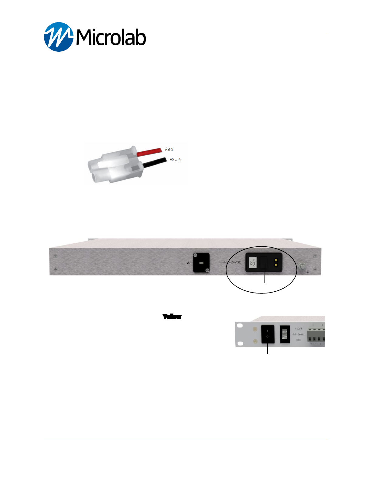
GPSS216 - Front and Rear Panels
Note: Product appearance varies by model
Antenna
Status
LEDs
Carefully unpack the GPSS216 remote unit
and check for damaged or missing parts. The
remote unit ships with the following:
• GPSS216 Head-End Unit (1RU EIA Rack)
• PSM-129 Pre-assembled connector power
cable (72” long)
• Quick Start Guide
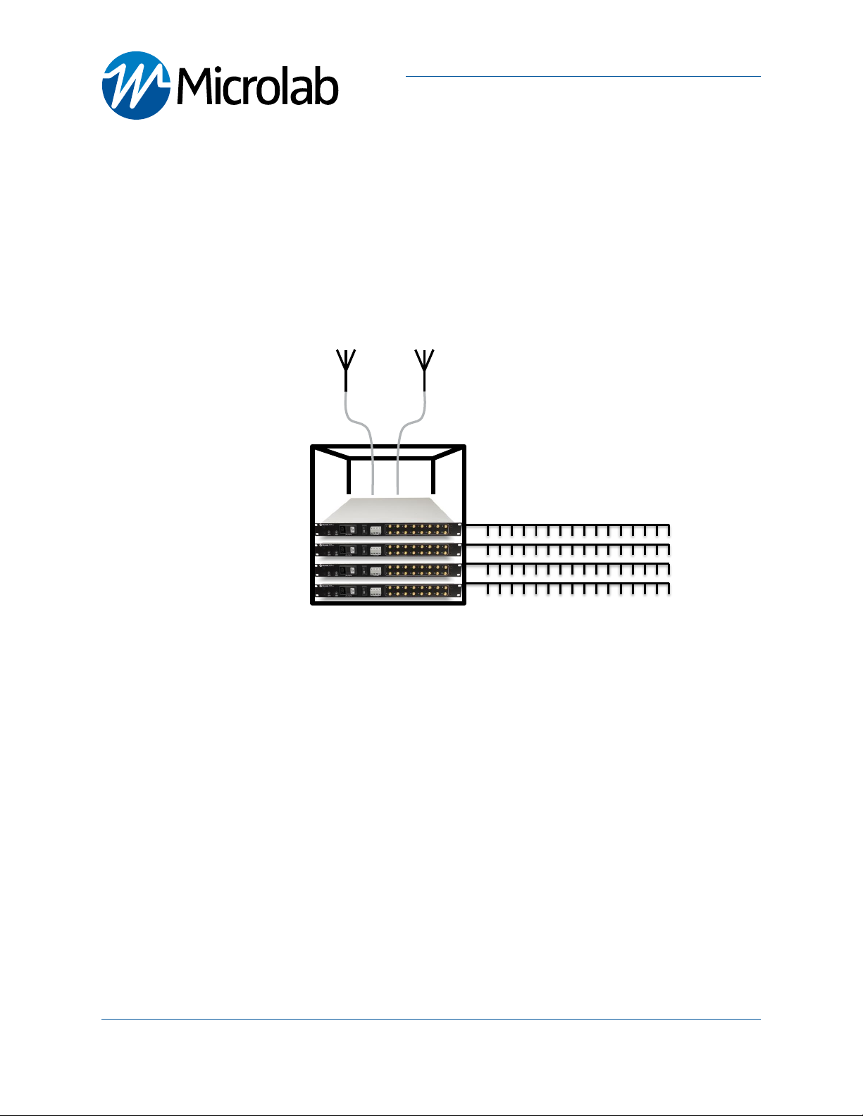
Microlab’s Lossless GPS Signal Splitters can be used to distribute UTC synchronization to up to 32 remote units
located where the GPS signals are not readily available. The GPS signal quality is actively monitored by this system
and can be combined other Microlab Lossless GPS Signal Splitters to expand the RF outputs. It offers 16-channel
and 32-channel options.
Gain
Switch
Introduction
Model Description
GPSS216 Lossless GPS signal splitter, 2RF inputs, 16 RF output, 1RU
GPSS232 Lossless GPS signal splitter, 2RF inputs, 32 RF output, 2RU
Hardware Needed
The following items are recommended for Setup and opera-
tion:
• Four (4) screws/washers (consult your rack requirements)
• Screwdriver
• -48/+24VDC power supply with included power cable
• TA-1MF SMA(m) terminations for each unused output
port (Recommended)
GPS Signal Splitter Models
Power
Switch
RF Outputs
SMA (f)
Alarms
Inputs
DC Power
Module
Ground Post
Rear Panel
Front Panel
Factory
Debug
Antenna
Inputs
SMA Female

Microlab, A Wireless Telecom Group Company, 25 Eastmans Road, Parsippany, NJ 07054
Tel: (973) 386-9696 • [email protected] • www.microlabtech.com • Fax: (973) 386-9191
System Connection Diagram
The following diagram illustrates how the GPS signal splitter is utilized
Mounting Installation
This GPS signal transmission system is designed to be setup by professional communications systems
installers.
The GPSS216 requires DC Power (-48/+24VDC). The DC interface mates with the included power cable model
PSM-129. Mount the GPSS216 Head-End Unit in close proximity to the eNode B or BBU to minimize cable
lengths.
Install the rack-mount GPSS216 on an EIA standard 19” rack using standard hardware and practices
GPSS216 Quick Start Guide
Lossless GPS Signal Splitter, 16 RF Ouput
page 2
Up to 16 BBU
GPSS216 –16 RF outputs, 1RU
Up to 16 BBU
Up to 16 BBU
Up to 16 BBU
Redundant GPS antenna inputs
or
GPSR116 GPS repeater
Scalable RF outputs

Follow these steps for connecting and disconnecting RF cables to the unit. Ground the unit, make all RF con-
nections and terminate all unused RF connections before applying DC Power.
Connect RF cables as shown in the System Connection Diagram.
Sequence to connect:
1. Connect System Ground.
- The remote unit comes with a .25-20FLANGENUT grounding lug. A grounding wire of suitable
gauge must be used to ground to a common bus bar in the Telecom room according to local and
building regulations.
2. Connect each RF Output (Ports 1 through 16) to each eNode B or BBU GPS inputs
- Apply appropriete torque to SMA connectors
- It is recommended that all unsued RF outputs MUST be terminated with a 50Ω load
See Microlab TA-1MF terminations
Microlab, A Wireless Telecom Group Company, 25 Eastmans Road, Parsippany, NJ 07054
Tel: (973) 386-9696 • [email protected] • www.microlabtech.com • Fax: (973) 386-9191
Connections RF and Ground
GPSS216 Quick Start Guide
Lossless GPS Signal Splitter, 16 RF Ouput
page 3
Ground Lug
SMA RF Outputs

3. Connect GPS Antennas to ports ANT1 and ANT2
- Two (2) Antennas recommended for redundancy
- One (1) Antenna required for operation
- Terminating unused Antenna port is not required. High Input Isolation.
- Only use operator approved GPS Antennas
- Apply appropriete torque to SMA connectors
Microlab, A Wireless Telecom Group Company, 25 Eastmans Road, Parsippany, NJ 07054
Tel: (973) 386-9696 • [email protected] • www.microlabtech.com • Fax: (973) 386-9191
Connections RF and Ground (Continued)
GPSS216 Quick Start Guide
Lossless GPS Signal Splitter, 16 RF Ouput
page 4
ANT2ANT1
Note: DC supply to antenna ports is +5V nominal, 100mA max

Power up Sequence:
Required:
• -48/+24VDC power source with the included power cable model PSM-129. Follow wiring diagram shown
1. Carefully align and mate the power cable DC connector to the Head-End unit’s DC ONLY power receptacle
2. Turn on DC power source and Switch On the unit
- Both Antenna Status LEDs will flash Yellow during bootup
- Wait 1 minute for device bootup
- Solid GREEN Antenna LEDs indicate normal operation
- See LED/Antenna Verification section for details
- Off Status LEDs indicate that power supply is not functioning
or not connected.
Microlab, A Wireless Telecom Group Company, 25 Eastmans Road, Parsippany, NJ 07054
Tel: (973) 386-9696 • [email protected] • www.microlabtech.com • Fax: (973) 386-9191
Connecting Power
Connect DC Positive and Negative terminals as
follow:
1. Red (Positive (+)/Required)
2. Black (Negative (-)/Required)
Power Cable
Power
Switch
GPSS216 Quick Start Guide
Lossless GPS Signal Splitter, 16 RF Ouput
page 5
DC ONLY

1. Verify Antenna LEDs turn solid GREEN to ensure Normal operation
- Allow up to 5 minutes for GPS signal acquisition.
- If GPS signal is locked on a given antenna, respective LED will illuminate solid GREEN.
- Mask Requirements: SNR > 15 dB, Elevation > 10 degrees, PDOP > 6
- Antenna will automatically switch over to secondary when primary goes into abnormal condition
Microlab, A Wireless Telecom Group Company, 25 Eastmans Road, Parsippany, NJ 07054
Tel: (973) 386-9696 • [email protected] • www.microlabtech.com • Fax: (973) 386-9191
LED/Antenna Verification
GPSS216 Quick Start Guide
Lossless GPS Signal Splitter, 16 RF Ouput
page 6
Antenna Status/GPS Lock Status LED Status
Normal (GPS Lock) Solid GREEN
Fault (GPS No Lock)Flashing GREEN and RED
Open Circuit or no connection Solid Yellow
Short circuit Solid RED

Microlab, A Wireless Telecom Group Company, 25 Eastmans Road, Parsippany, NJ 07054
Tel: (973) 386-9696 • [email protected] • www.microlabtech.com • Fax: (973) 386-9191
The LNAs (low noise amplifiers) inside the GPSS216 provide a +10dB
system gain. Gain is defined as the ratio in the amount of RF power
of the output and input of the GPSS216.
1. Verify all unused outputs are terminated with 50Ω loads.
2. Set Gain Select switch to the +10dB position (maximum gain)
3. Verify signal level at the ouput is sufficient for the next system
stage
Gain Select
GPSS216 Quick Start Guide
Lossless GPS Signal Splitter, 16 RF Ouput
page 7
Sequence to Disconnect:
1. Turn Down gain (Set Gain Select switch to the 0dB position)
2. Switch OFF the unit
3. Remove/Disconnect DC power to the device
4. Disconnect the RF (input/output) connections of the unit.
5. Disconnet Ground
6. Unmount Unit
Disconnecting/Uninstalling
Gain Select
Switch

Microlab, A Wireless Telecom Group Company, 25 Eastmans Road, Parsippany, NJ 07054
Tel: (973) 386-9696 • [email protected] • www.microlabtech.com • Fax: (973) 386-9191
Disclaimer
GPS and GNSS re-transmission to an antenna requires regulatory approval. These approvals are granted on an
individual basis by regulating bodies. Microlab cannot grant these approvals, and cannot be held responsible
for violating these regulations using the system.
The FCC requires commercial users within the US to acquire and maintain a Part 5 experimental license to
re-broadcast GPS signals. Licenses are not required if they are inside an RF shielded environment. European
regulations vary by country. Consult local authorities for additional details.
Contact Microlab - Active Solutions
To contact Microlab, visit our website at www.microlabtech.com or send email to [email protected].
For operating assistance in the USA, call (973) 386-9696.
Safety Information
To avoid possible electric shock or personal injury, the following general safety precautions must be observed
during all phases of operation, service, or repair of the Microlab Unit . Failure to comply with these precautions
or with specific warnings in this guide violates the safety standards of design, manufacture, and intended
use of the Microlab Unit. Microlab assumes no liability for the customer’s failure to comply with these require-
ments.
GPSS216 Quick Start Guide
Lossless GPS Signal Splitter, 16 RF Ouput

Microlab, A Wireless Telecom Group Company, 25 Eastmans Road, Parsippany, NJ 07054
Tel: (973) 386-9696 • [email protected] • www.microlabtech.com • Fax: (973) 386-9191
Page Intentionally Left Blank
GPSS216 Quick Start Guide
Lossless GPS Signal Splitter, 16 RF Ouput
Table of contents