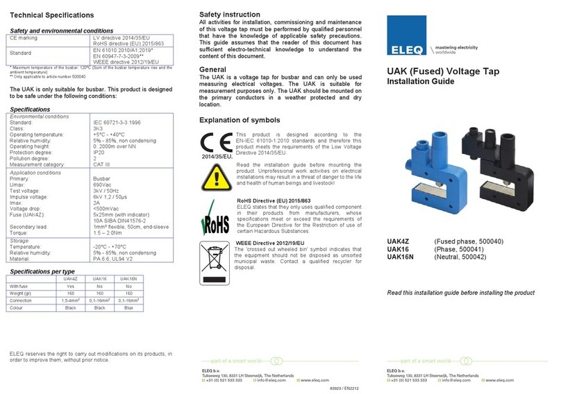
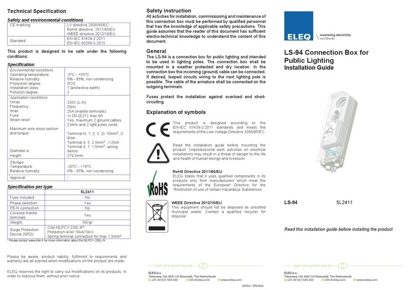
ELEQ LS-94 User manual

83699
/ EN1510
Technical Specification
Safety and environmental conditions
CE marking
LV directive 2006/95/EC
RoHS directive 2011/65/EU
WEEE directive 2012/19/EU
Standard
EN-IEC 61439-2:2011
EN-IEC 60269-3:2013
This product is designed to be safe under the following
conditions:
Specification
Environmental conditions
Operating temperature:
Relative humidity:
Protection degree:
Installation class:
Pollution degree:
-5°C - +55°C
5% - 85%, non condensing
IP23
1 (protective earth)
2
Application conditions
Umax:
Frequency:
Imax:
Imax to armature:
Fuse:
Strain relief:
Maximum wire cross section
and torque :
Diameter ø
Height
230/400V
50Hz
50A (mantle terminals)
6A per fuse
2x DII (E27), max 6A each
Yes, maximum two ground cables
23mm and 2 light poles cords
Terminal N, 1, 2, 3, PE: 2x 10mm2
or 3x 6mm2, 2-4Nm
Terminal 5, 6, 7: 2.5mm2, 1-2Nm
94mm
279,5mm
Storage
Temperature:
Relative humidity:
-20°C - +70°C
5% - 85%, non condensing
Approval KEMA-Keur
Specification per type
5L2301 5L2302 5L2303 5L2304 5L2305 5L2306 5L2307
Fuse
included
1x 4A 1x 6A 2x 6A 2x 4A 1x 6A
PE-N
connection Yes Yes Yes Yes
Covered
Terminals Yes
Weight 660gr 570gr 570gr 660gr 750gr 750gr 660gr
Please be aware, product liability, fulfillment to requirements and
warranty are all expired when modifications on the product are made.
ELEQ reserves the right to carry out modifications on its products, in
order to improve them, without prior notice.
Safety instruction
All activities for installation, commissioning and maintenance of
this connection box must be performed by qualified personnel
that has the knowledge of applicable safety precautions. This
guide assumes that the reader of this document has sufficient
electro-technical knowledge to understand the content of this
document.
General
The LS-94 is a connection box for public lighting and intended
to be used in lighting poles. The connection box should be
mounted in a weather protected and dry location. In the
connection box the incoming (ground) cable can be connected.
If desired, looped circuits wiring to the next lighting pole is
possible. The cable of the armature should be connected on
the outgoing terminals.
Fuses protect the installation against overload and short-
circuiting.
Explanation of symbols
This product is designed according to the
EN-IEC 61439-2:2011 standards and meets the
requirements of the Low Voltage Directive 2006/95/EC.
Read the installation guide before mounting the
product. Unprofessional work activities on electrical
installations may result in a threat of danger to the life
and health of human beings and livestock!
RoHS Directive 2011/65/EU
ELEQ states that it uses qualified components in its
products only from manufacturers which meet the
requirements of the European Directive for the
"Restriction of use of certain Hazardous Substances
WEEE Directive 2012/19/EU
This equipment should not be disposed as unsorted
municipal waste. Contact a qualified recycler for
disposal.
LS-94 Connection Box for
Public Lighting
Installation Guide
LS-94 5L2301
5L2302
5L2303
5L2304
5L2305
5L2306
5L2307
Read this installation guide before installing the product
5L2303
83699
/ EN1510
Technical Specification
Safety and environmental conditions
CE marking
LV directive 2006/95/EC
RoHS directive 2011/65/EU
WEEE directive 2012/19/EU
Standard
EN-IEC 61439-2:2011
EN-IEC 60269-3:2013
This product is designed to be safe under the following
conditions:
Specification
Environmental conditions
Operating temperature:
Relative humidity:
Protection degree:
Installation class:
Pollution degree:
-5°C - +55°C
5% - 85%, non condensing
IP23
1 (protective earth)
2
Application conditions
Umax:
Frequency:
Imax:
Imax to armature:
Fuse:
Strain relief:
Maximum wire cross section
and torque :
Diameter ø
Height
230/400V
50Hz
50A (mantle terminals)
6A per fuse
2x DII (E27), max 6A each
Yes, maximum two ground cables
23mm and 2 light poles cords
Terminal N, 1, 2, 3, PE: 2x 10mm2
or 3x 6mm2, 2-4Nm
Terminal 5, 6, 7: 2.5mm2, 1-2Nm
94mm
279,5mm
Storage
Temperature:
Relative humidity:
-20°C - +70°C
5% - 85%, non condensing
Approval
KEMA-Keur
Specification per type
5L2301
5L2302
5L2303
5L2304
5L2305
5L2306
5L2307
Fuse
included
1x 4A
1x 6A
2x 6A
2x 4A
1x 6A
PE-N
connection
Yes
Yes
Yes
Yes
Covered
Terminals
Yes
Weight
660gr
570gr
570gr
660gr
750gr
750gr
660gr
Please be aware, product liability, fulfillment to requirements and
warranty are all expired when modifications on the product are made.
ELEQ reserves the right to carry out modifications on its products, in
order to improve them, without prior notice.
Safety instruction
All activities for installation, commissioning and maintenance of
this connection box must be performed by qualified personnel
that has the knowledge of applicable safety precautions. This
guide assumes that the reader of this document has sufficient
electro-technical knowledge to understand the content of this
document.
General
The LS-94 is a connection box for public lighting and intended
to be used in lighting poles. The connection box should be
mounted in a weather protected and dry location. In the
connection box the incoming (ground) cable can be connected.
If desired, looped circuits wiring to the next lighting pole is
possible. The cable of the armature should be connected on
the outgoing terminals.
Fuses protect the installation against overload and short-
circuiting.
Explanation of symbols
This product is designed according to the
EN-IEC 61439-2:2011 standards and meets the
requirements of the Low Voltage Directive 2006/95/EC.
Read the installation guide before mounting the
product. Unprofessional work activities on electrical
installations may result in a threat of danger to the life
and health of human beings and livestock!
RoHS Directive 2011/65/EU
ELEQ states that it uses qualified components in its
products only from manufacturers which meet the
requirements of the European Directive for the
"Restriction of use of certain Hazardous Substances
WEEE Directive 2012/19/EU
This equipment should not be disposed as unsorted
municipal waste. Contact a qualified recycler for
disposal.
LS-94 Connection Box for
Public Lighting
Installation Guide
LS-94 5L2301
5L2302
5L2303
5L2304
5L2305
5L2306
5L2307
Read this installation guide before installing the product
5L2303
83699 / EN1603
ELEQ b.v.
Tukseweg 130, 8331 LH Steenwijk, The Netherlands
ELEQ b.v.
Tukseweg 130, 8331 LH Steenwijk, The Netherlands

Always avoid working on live parts of an installation.
Functional Description
The terminal boxes of the 5L230x series all are intended to be
fitted with one or two DII fuses. The fuse capacity is limited to
max 6A.
A connection between PE and the frame of the lighting pole is
made automatically by mounting the terminal box to the lighting
pole.
Assembly
1. Ensure a safe working area during assembly, maintenance
and inspection of the connection box. Disconnect the power
of the main circuit and make sure it can not be enabled
unintentionally.
2. Remove the transparent lid, mounted fuses and the
intermediate cover.
3. Mount the connection box with the upper and lower
connection in the lighting pole.
4. Connect the incoming and (if present) outgoing ground
cable to terminals N, 1, 2, 3 and PE.
5. Mount the outgoing cables to the armature(s).
6. Tightly mount strain relief block.
7. Check if the connections are mounted properly and firmly.
8. Install the fuse(s). Fuse type: DII (E27), max 6A.
9. Mount the transparent lid and screw tightly.
Incoming
N = Neutral
PE = Protective earth
1 = phase L1
2 = phase L2
3 = phase L3
Outgoing
5 = Neutral
6 = fused phase L1
7 = fused phase L3
If required, incoming terminals N,
PE, 1, 2 and 3 can be looped to the
next lighting pole.
Wiring Diagram
Maintenance and inspection
The connection box should be situated on a dry and clean
location.
The connection box should be mounted firmly.
The connections should be mounted firmly.
Attention
Always avoid working on live parts of an installation.
Disassembly instruction
Disconnect the power of the main circuit and make sure it can
not be enabled unintentionally.
1. Unmount the transparent lid.
2. Remove the fuses.
3. Remove the strain relief block.
4. Disconnect the ground cables.
5. Disconnect the connection box from the lighting pole.
Recycling
When the product has reached ‘end of life’, it must be recycled.
Do not dispose this product as unsorted municipal waste.
Contact a qualified recycler for disposal.
Always avoid working on live parts of an installation.
Functional Description
The terminal boxes of the 5L230x series all are intended to be
fitted with one or two DII fuses. The fuse capacity is limited to
max 6A.
A connection between PE and the frame of the lighting pole is
made automatically by mounting the terminal box to the lighting
pole.
Assembly
1. Ensure a safe working area during assembly, maintenance
and inspection of the connection box. Disconnect the power
of the main circuit and make sure it can not be enabled
unintentionally.
2. Remove the transparent lid, mounted fuses and the
intermediate cover.
3. Mount the connection box with the upper and lower
connection in the lighting pole.
4. Connect the incoming and (if present) outgoing ground
cable to terminals N, 1, 2, 3 and PE.
5. Mount the outgoing cables to the armature(s).
6. Tightly mount strain relief block.
7. Check if the connections are mounted properly and firmly.
8. Install the fuse(s). Fuse type: DII (E27), max 6A.
9. Mount the transparent lid and screw tightly.
Incoming
N = Neutral
PE = Protective earth
1 = phase L1
2 = phase L2
3 = phase L3
Outgoing
5 = Neutral
6 = fused phase L1
7 = fused phase L3
If required, incoming terminals N,
PE, 1, 2 and 3 can be looped to the
next lighting pole.
Wiring Diagram
Maintenance and inspection
The connection box should be situated on a dry and clean
location.
The connection box should be mounted firmly.
The connections should be mounted firmly.
Attention
Always avoid working on live parts of an installation.
Disassembly instruction
Disconnect the power of the main circuit and make sure it can
not be enabled unintentionally.
1. Unmount the transparent lid.
2. Remove the fuses.
3. Remove the strain relief block.
4. Disconnect the ground cables.
5. Disconnect the connection box from the lighting pole.
Recycling
When the product has reached ‘end of life’, it must be recycled.
Do not dispose this product as unsorted municipal waste.
Contact a qualified recycler for disposal.
Other ELEQ Cables And Connectors manuals
Popular Cables And Connectors manuals by other brands
Tektronix
Tektronix Keithley 4200-TRX Series instruction sheet
Eagle
Eagle E250EG product manual
DX Engineering
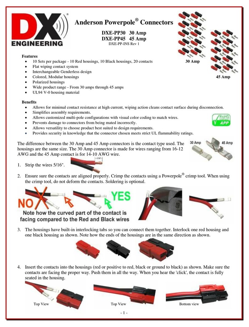
DX Engineering Anderson Powerpole DXE-PP30 manual
Super Handy
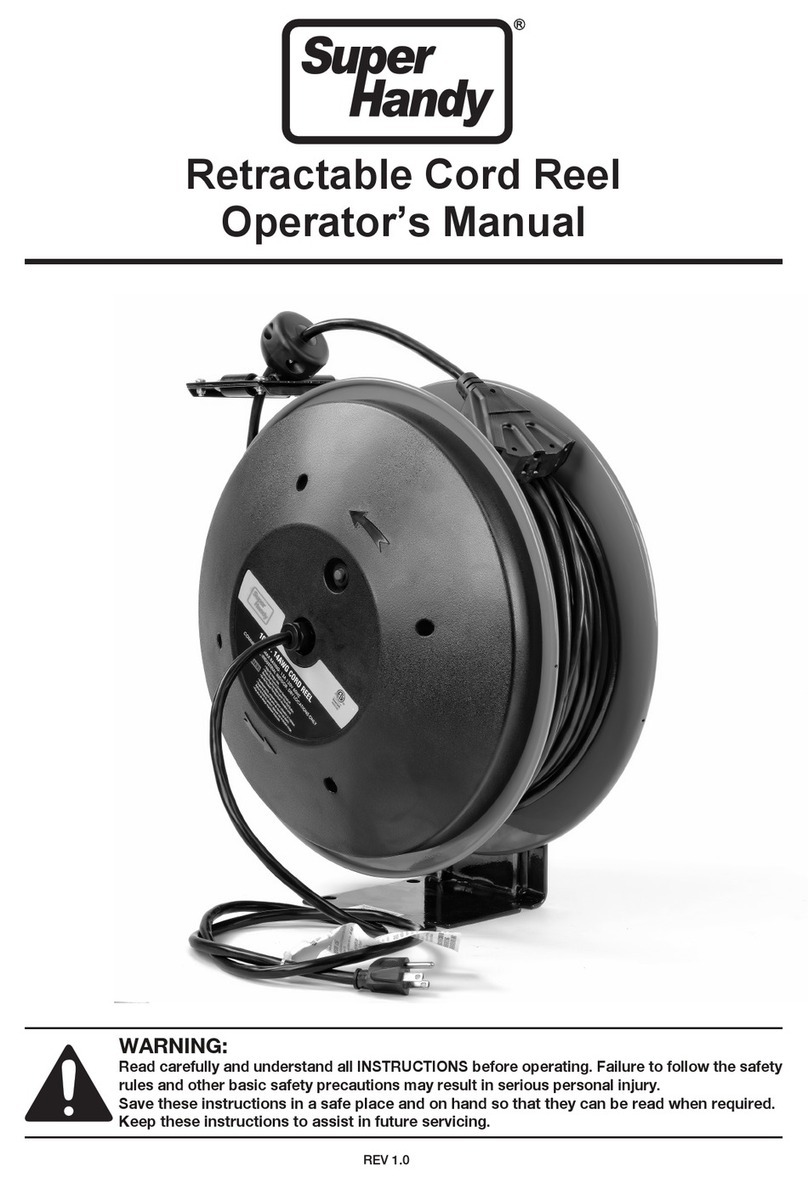
Super Handy GUR058 Operator's manual
Connective Peripherals
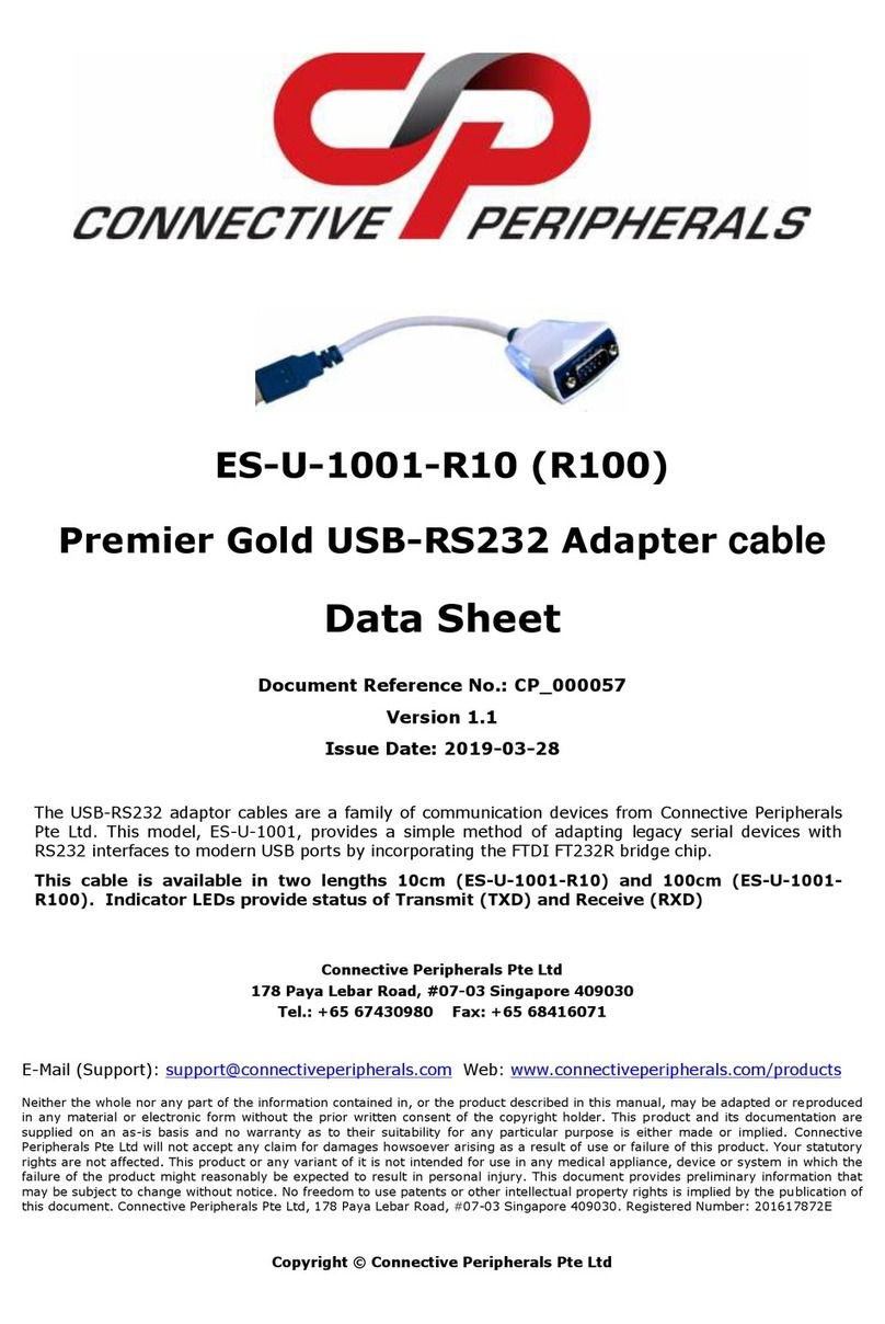
Connective Peripherals ES-U-1001-R10 datasheet
Humminbird
Humminbird NMEA 2000 module installation guide

