Micromedical VisualEyes 505 User manual

Instructions for Use - US
Micromedical
VisualEyesTM 505
by Interacoustics
D-0115288 –C –2018/02

Copyright © by Interacoustics. All rights reserved. Information in this document is subject to change
without notice. Companies, names, and data used in example herein are fictitious unless otherwise
noted. No part of this document may be reproduced or transmitted in any form or by any means,
electronic or mechanical, for any purpose, without express written permission of Interacoustics A/S or
its licensees.
FireWire® is a registered trademark of Apple Inc., registered in the United States and other countries.
Windows® is a registered trademark of the Microsoft Corporation, registered in the United States and
other countries.

Table of Contents
1INTRODUCTION...........................................................................................................................1
About this manual ............................................................................................................... 1
Intended use ....................................................................................................................... 1
Product description ............................................................................................................. 1
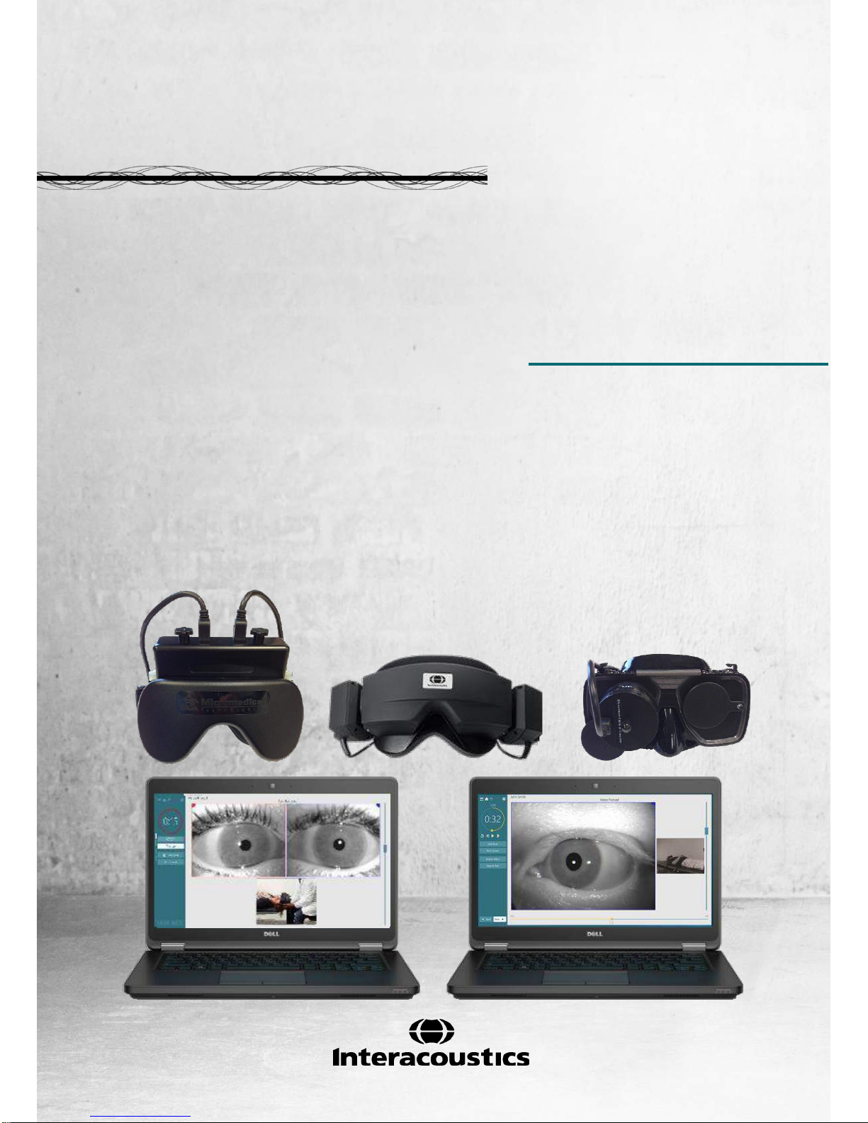
1.3.1 System configurations .............................................................................................. 1
1.3.2 Minimum requirements to PC................................................................................... 2
1.3.3 ncluded and optional parts ....................................................................................... 2
Warnings and precautions.................................................................................................. 4
2UNPACKING AND INSPECTION.................................................................................................7
Unpacking and inspection................................................................................................... 7
Reporting imperfections...................................................................................................... 7
Marking ............................................................................................................................... 8
3SETUP AND INSTALLATION ......................................................................................................9
Introduction to VisualEyes™ VF 505 software suite........................................................... 9
Installation of OtoAccess™ database ................................................................................. 9
Installation of VisualEyes™ 505 software........................................................................... 9
Uninstall software................................................................................................................ 9
Hardware setup................................................................................................................. 10
3.5.1 Laptop / PC............................................................................................................. 10
3.5.2 The VisualEyes™ 505 video fenzel goggles .......................................................... 10
3.5.3 Side mount camera goggles................................................................................... 10
3.5.4 Top mount camera goggles.................................................................................... 11
3.5.5 Front mount camera goggles.................................................................................. 11
3.5.6 Foot Pedal .............................................................................................................. 11
3.5.7 VisualEyes™ remote control .................................................................................. 12
3.5.8 External room camera ............................................................................................ 12
Connection layout ............................................................................................................. 13
4PATIENT ENTRY........................................................................................................................15
Entering patient information.............................................................................................. 15
Licensing........................................................................................................................... 16
Micromedical VisualEyes™ main screen.......................................................................... 17
4.4 Room recording................................................................................................................. 17
4.5 Patient preparation............................................................................................................ 17
4.6 Testing the Patient............................................................................................................ 18
4.6.1 Starting the test....................................................................................................... 18
4.6.2 Pausing the test...................................................................................................... 18
4.6.3 Ending the test........................................................................................................ 18
4.6.4 Additional Functions ............................................................................................... 18
4.7 Session Review and Write Report .................................................................................... 18
4.8 Additional information ....................................................................................................... 18
5CARE AND MAINTENANCE......................................................................................................19
General maintenance procedures..................................................................................... 19
How to clean the VisualEyes™ system ............................................................................ 19
Warranty and Service ....................................................................................................... 20
5.3.1 PRODUCT LIFE ..................................................................................................... 20
5.3.2 PRODUCT SERVICE............................................................................................. 20
5.3.3 PRODUCTS RETURNED FOR REPAIR ............................................................... 21
5.3.4 WARRANTY DETERMINATION ............................................................................ 21
5.3.5 EXTENDED WARRANTY....................................................................................... 21
5.3.6 SERVICE CONTRACT........................................................................................... 21
5.3.7 NON-WARRANTY FACTORY REPAIRS............................................................... 21

6GENERAL TECHNICAL SPECIFICATIONS..............................................................................23
PC Hardware and Software .............................................................................................. 23
Operation and storage specifications ............................................................................... 23
Standards.......................................................................................................................... 23
Component specifications................................................................................................. 23
Electromagnetic compatibility (EMC)................................................................................ 25
6.5.1 Electromagnetic compatibility (EMC) for top-mounted goggles ............................. 25
6.5.2 Electromagnetic compatibility (EMC) for side mounted goggles............................ 27

VisualEyes™505 Instructions for Use –US Page 1
1Introduction
About this manual
This manual is valid for the VisualEyes™ 505 Software version 2.1. This product is manufactured by:
Interacoustics A/S
Audiometer Allé 1
5500 Middelfart
Denmark
Tel.: +45 6371 3555
Fax: +45 6371 3522
Web: www.interacoustics.com
Distribution and service: Micromedical Technologies Inc.
10 Kemp Drive
Chatham, IL 62629
USA
Tel.: 1 (800) 334-4154
Web: www.micromedical.com
Intended use
The VisualEyes™ 505 is a Video Frenzel system which provides information to assist in the evaluation,
diagnosis and documentation of vestibular disorders. Nystagmus of the eye is recorded by use of a goggle
mounted with cameras. These images are displayed and stored in the software.
This information then can be used by a trained medical professional to assist in diagnosing vestibular
disorders. The target population for VisualEyes™ 505 is 5 years of age+.
The VisualEyes™ 505 is to be used by trained personnel only, such as audiologists, Physical therapists,
ENT surgeons, doctors, hearing healthcare professionals or personnel with a similar level of qualifications.
The device should not be used without the necessary knowledge and training to understand its use and how
results should be interpreted.
Federal law restricts the sale, distribution, or use of this device to, by, or on the order of a licensed
medical practitioner
NOTICE
VisualEyes™ 505 testing may be contrainidicated in patients who exhibit the following: blindness, broken
nose or other face/head trauma, recent eye surgery and ptosis.
Product description
VisualEyes™ 505 consists of a goggle with one or two camers that are connected to a computer and
dedicated software. Additional parts may also be included as specified in section 1.3.3.
1.3.1 System configurations
The VisualEyes™ 505 is available in 2 different configurations:
1. VisualEyes™ 505 monocular: One camera, eye images are displayed and stored for later replay.
Option for external situation recording.
2. VisualEyes™ 505 binocular: Two cameras, eye images are displayed and stored for later replay.
Option for external situation recording.

VisualEyes™505 Instructions for Use –US Page 2
1.3.2 Minimum requirements to PC
Laptop PC: One 34 mm PCExpressCard slot available (for side mount FireWire®camera goggles only).
Desktop PC: One PCIExpress card available. (for side mount FireWire®camera goggles only).
Intel i5 processor 2.5 GHz or better.
Minimum 4 GB RAM or more.
Hard drive with min. 250GB space.
Minimum display of 1366X768 (Higher resolution recommended).
Operating Systems supported:
Windows®7 32-bit or 64-bit.
Windows® 8.1 64-bit.
Windows® 10 64-bit.
1.3.3 Included and optional parts
As standard, VisualEyes™ 505 system is delivered with the following:
USB camera systems
FireWire® camera systems
Included parts
Remote Control or Foot pedal
Instructions for Use
VisualEyes™ 505 installation media
OtoAccess™ Database media
VisualEyes™ 505 Quick Start Guide
Optional parts
based on goggle
type
2D-VOGfw goggle w. side
mounted cameras
USB 2.0 Camera module (two
modules in binocular configuration)
Disposable goggle foam pads –Box
of 24 pcs
1.5 mm hexagon screwdriver for
camera retaining screws
7-port USB 3.0 hub w. external
power supply
USBM2.1A goggle w. front
mounted camera
Adult mask for USB monocular
camera
Camera module with 15’ USB cable
7-port USB 3.0 hub w. external
power supply
USBM2.1P goggle w. front
mounted camera
Pediatric mask for USB monocular
camera
Camera module with 15’ USB cable
A to Mini B
7-port USB 3.0 hub w. external
power supply
2D-VOGfw goggle w. side mounted
cameras
FireWire®camera module (two modules
in binocular configuration)
Disposable goggle foam pads –Box of
24 pcs
PCExpressCard Stabilization kit (laptop
configuration)
PCExpressCard (for laptop
configuration)
PCI ExpressCard (for tower PC
configuration)
4-port USB hub

VisualEyes™505 Instructions for Use –US Page 3
BG4.0KUSB goggle w. top
mounted cameras
Goggles USB Asian faceplate
binocular
Two 15’ USB cables A to Mini B
7-port USB 3.0 hub w. external
power supply
BG4.0USB goggle w. top mounted
cameras
Goggles USB binocular
Two 15’ USB cables A to Mini B
7-port USB 3.0 hub w. external
power supply
Table 1. VisualEyes™ 505 included and optional parts

VisualEyes™505 Instructions for Use –US Page 4
Warnings and precautions
WARNING indicates a hazardous situation which, if not avoided, could result
in death or serious injury.
CAUTION, used with the safety alert symbol, indicates a hazardous situation
which, if not avoided, could result in minor or moderate injury.
NOTICE
NOTICE is used to address practices not related to personal injury.
1. A Separation Device (isolation device) is needed to isolate the equipment located outside the patient
environment from the equipment located inside the patient environment. In particular such a
Separation Device is required when a network connection is made. The requirement for the
Separation Device is defined in IEC 60601-1, edition 3, clause 16.
2. The system must not be used in presence of explosive or flammable gases.
3. The goggle should not be worn by patients with strong defective vision and abnormal rare blink.
Please consult a specialist in such circumstances before using the mask on these types of patients.
4. The system must be switched off before cleaning.
5. Do not use any additional multiple socket-outlet or extension cord.
6. No modification of this equipment is allowed without Interacoustics authorization.
7. The manufacturer will make available on request circuit diagrams, component part lists, descriptions,
calibration instructions, or other information that will assist service personnel to repair those parts of
this system that are designated by the manufacturer as repairable by authorized service personnel.
8. For maximum electrical safety, turn off the power from a mains powered instrument when it is left
unused.
9. The instrument is not protected against harmful ingress of water or other liquids. If any spillage
occurs check the instrument carefully before use or return for service.
10. Do not use the equipment if it is showing visible damage.
1. Use this device only as described in this manual.
2. The system must be serviced at least once a year. The service must verify system functionality.
3. Do not use the equipment if the equipment is broken. Have the equipment serviced.
4. Only personnel with proper training (skilled personnel) should operate the system.
5. Proper use of this device depends on careful reading of this manual and all additional instructions
and labels.
6. Let the system obtain room temperature before turning it on. Extra time for obtaining room.
temperature may be needed to avoid condensation if the system has been moved from a very cold
location to a warmer one.
7. The patients or test persons should not wear any optical utilities such as glasses or contact lenses.
8. The patients or test persons should not wear make up around the eyes.

VisualEyes™505 Instructions for Use –US Page 5
9. It is recommended that parts which are in direct contact with the patient (e.g. disposable goggle
foam pads) should only be used with one patient, and should therefore be discarded after each
session.
10. Be sure to use only stimulation movements that are acceptable to the patient.
NOTICE
1. To prevent system faults take appropriate precautions to avoid PC viruses and similar.
2. Clean the camera lens and the infrared coated mirrors of the goggle regularly to avoid shadows on
the displayed images.
3. Do not drop and avoid other undue impacts to this device. If the instrument is dropped or otherwise
damaged, return it to the manufacturer for repair and/or calibration. Do not use the instrument if any
damage is suspected.
4. Although the instrument fulfils the relevant EMC requirements precautions should be taken to avoid
unnecessary exposure to electromagnetic fields, e.g. from mobile phones etc. If the device is used
adjacent to other equipment it must be observed that no mutual disturbance appears.
Within the European Union it is illegal to dispose electric and electronic waste as
unsorted municipal waste. Electric and electronic waste may contain hazardous
substances and therefore has to be collected separately. Such products will be marked
with the crossed-out wheeled bin shown below. The cooperation of the user is
important in order to ensure a high level of reuse and recycling of electric and
electronic waste. Failing to recycle such waste products in an appropriate way may
endanger the environment and consequently the health of human beings.

VisualEyes™505 Instructions for Use –US Page 6

VisualEyes™505 Instructions for Use - US Page 7
2Unpacking and inspection
Unpacking and inspection
Check box and contents for damage
When the instrument is received, please check the shipping box for rough handling and damage. If the box is
damaged it should be kept until the contents of the shipment have been checked mechanically and
electrically. If the instrument is faulty, please contact your local distributor. Keep the shipping material for the
carrier’s inspection and insurance claim.
Keep carton for future shipment
VisualEyes™ 505 comes in its own shipping carton, which is specially designed. Please keep this carton. It
will be needed if the instrument has to be returned for service. If service is required, please contact your
local distributor.
Reporting imperfections
Inspect before connection
Prior to connecting the product it should once more be inspected for damage. All of the cabinet and the
accessories should be checked visually for scratches and missing parts.
Report immediately any faults
Any missing part or malfunction should be reported immediately to the supplier of the instrument together with
the invoice, serial number, and a detailed report of the problem. In the back of this manual, you will find a
‘Return Report’where you can describe the problem.
Products returned for repair
If the manufacturer requests that you return the product for evaluation or repair, pack the product well,
preferably in the original shipping container with a Return Material Authorization (RMA) number provided by
the manufacturer. Systems with optional rotational chairs will be serviced on-site by the local distributor.

VisualEyes™505 Instructions for Use - US Page 8
Marking
The following marking can be found on the instrument:
Symbol
Explanation
Type BF applied parts.
Type B applied parts.
Follow instructions for use.
WEEE (EU-directive).
This symbol indicates that when the end-user wishes to discard this product,
it must be sent to separate collection facilities for recovery and recycling.
Failing to do so may endanger the environment.
0123
The CE-mark indicates that the manufacturer meets the requirements of
Annex II of the Medical Device Directive 93/42/EEC for the quality system.
Year of Manufacturer.
Manufacturer
Do not re-use.
Parts like foam cushions and similar are for single use only.
Reference number used to denote the model of the equipment.
Legend of Symbols.

VisualEyes™505 Instructions for Use - US Page 9
3Setup and installation
Introduction to VisualEyes™ VF 505 software suite
The VisualEyes™ 505 combines leading edge technology with touch screen capability in a new streamline
software interface. The VisualEyes™ 505 provides information to assist in the evaluation, diagnosis and
documentation of vestibular disorders. Eye movements are recorded by use of a goggle mounted with one or
two infrared video cameras. The eye images are displayed in real time in large format on a computer
monitor. External environments (room) are recorded by use of an integrated / external USB camera if
desired. Patient interview is recorded separately for recording patient’s medical history. This information can
then be used by a trained medical professional to assess vestibular disorders.
Installation of OtoAccess™database
The VisualEyes™ 505 software is accesssed through the Interacoustics OtoAccess™database. The
Interacoustics OtoAccess™ database is used for storage of patient information and data recordings.
Your computer/ laptop will have OtoAccess and VisualEyes™ software pre-installed.
If you find that it is not already installed, or if a re-install is required please read the instructions for use to
included with the OtoAccess™ installation media (CD or Flash drive) or contact your distributor.
Installation of VisualEyes™ 505 software
NOTICE
The OtoAccess™ database must be installed prior to installing VisualEyes™ software.
The VisualEyes™ software will be pre-installed on the computer purchased from the Interacoustics or
Micromedical. In the event when the software must be re-installed, please follow these instructions.
1. Insert the VisualEyes™ Installation CD or thumb drive into the computer.
2. If the installation procedure does not start automatically, click Start, then go to My Computer and
double click the DVD/CD-RW drive or Flash Drive to view the contents of the installation media.
3. Double click the Micromedical VisualEyes™ Installer file to initiate the installation.
4. The VisualEyes™ Setup Wizard will start.
5. Check the box to accept the terms and click Install.
6. After the installation completes, exit the installer.
7. Remove the installation media from the drive and store in a convenient place.
The VisualEyes™ 505 installation will configure OtoAccess™ for VisualEyes™ 505 testing. To use the
VisualEyes™ 505 software, select the Micromedical VisualEyes™ instrument from OtoAccess.
Uninstall software
In Windows® 7 and 8.1, the VisualEyes™ software can be removed from Programs and Features.
1. Open Windows® Control Panel and then select Programs and Features. If the Category option is
used, then under Programs choose Uninstall a program.
2. Select the Micromedical VisualEyes™ entry. Click on Uninstall.
3. In the installer package, choose Uninstall. Once the program is uninstalled, close the installer and
Control Panel.
In Windows® 10, the VisualEyes™ software can be removed from Settings.
1. From the start menu choose Settings.
2. Choose System, then select Apps & features.
3. In the sort box, choose Sort by name.
4. Select the Micromedical VisualEyes™ program in the list, then click on Uninstall.
5. Confirm the process by clicking on the Uninstall button.
In the installer package, choose Uninstall. Once the program is uninstalled, close the installer and
Settings.

VisualEyes™505 Instructions for Use - US Page 10
Hardware setup
The VisualEyes™ 505 is composed of several selected pieces of equipment. The software is designed to
be compatible with both Interacoustics a/s and Micromedical Technologies Inc. equipment.
Each piece of equipment, its function and installation is described below.
3.5.1 Laptop / PC
The VisualEyes™ 505 suite comes preloaded on a dedicated laptop or pc.
Figure 3.5.1 VisualEyes™ Laptop
3.5.2 The VisualEyes™ 505 video fenzel goggles
The Video Frenzel goggles allow for the recording of eye movements during various test conditions. In
order to achieve this the goggle holds FireWire®/ USB cameras that are used to record the eye images.
The FireWire® / USB cameras use infrared light (IR), which is not visible to the naked eye. The IR
illumination enables sessions to be performed in complete darkness.
3.5.3 Side mount camera goggles
The USB or FireWire® cameras are fixed on the sides of the goggle.
Figure 3.5.2 Side mount camera goggles
The goggles come with replaceable foam cushions that are easily removed between patients by simply
pulling the used foam cushion off of the Velcro pads on the inside of the mask and then aligning a new
foam cushion on top of the Velcro.
The front cover plate of the Combi mask is magnetically fixed and can easily be removed for visual
stimulation tests (i.e. oculomotor). The mask has an adjustable Velcro head strap that secures the
goggles while still providing patient comfort.
Monocular configuration with the side mount camera goggles will have a camera module on one side, and
the other side will be an empty camera module without adjustment knobs.

VisualEyes™505 Instructions for Use - US Page 11
3.5.4 Top mount camera goggles
The top mount camera goggles block out ambient light with the removable cover over the portal for vision-
denied testing. Side-lights on the goggle provide guidance/ illumination when placing the cover on the
goggles. On the left side of the goggles is a switch to start and stop tests. The goggles have an
adjustable Velcro head-strap that secures the goggles while still providing patient comfort.
Figure 3.5.3 Top mount camera goggles
3.5.5 Front mount camera goggles
The front mount camera goggles use a single USB camera pressed into the camera portal on the front of
the goggles mask. The camera can be pressed into either camera portal to record the desired eye. The
USB cable is secured in the cable clip above the portal. Each portal has a swivel cover plate to provide
vision-denied testing. The goggles have an adjustable head-strap that secures the goggles while still
providing patient comfort.
Figure 3.5.4 Front mount camera goggles
3.5.6 Foot Pedal
The foot pedal allows you to begin the measurement testing by pressing the foot switch so you have both
hands free to look after the patient (e.g. Dix Hallpike). Connection with the PC is via a USB port.
Figure 3.5.5 VisualEyes™ Foot pedal

VisualEyes™505 Instructions for Use - US Page 12
3.5.7 VisualEyes™ remote control
The remote control provides a hand held option for controlling and performing tests within the
VisualEyes™ suite. The operator can operate the software using the remote control while remaining at
the patient’s side during testing. The remote control’s receiver connects to the PC via a USB port, while
the remote control connects to the receiver using 2.4 GHz rf transmission.
Figure 3.5.6 VisualEyes™ Remote Control
1. Top button:
Centers eyes (top mount goggles only)
2. Right button:
Goes forward in the software
If the test is running, it stops the test
If in playback mode, the button will advance to the next test in the list
3. Left button:
Stops the test
4. Bottom button:
Turns on/off the fixation light during a test
3.5.8 External room camera
Figure 3.5.7 USB room camera
The room camera is an external device connected to the computer’s USB port. It serves to record the
external environment and patient testing process from the beginning. The external room camera provides
additional flexibility in recording the testing procedure, though the laptop’s integrated observation camera
can be used with orienting the computer towards the patient.

VisualEyes™505 Instructions for Use - US Page 13
Connection layout
Figure 3.6.1 Tower PC connection diagram
Figure 3.6.2 Laptop PC connection diagram
NOTICE
Always connect other IT-equipment before powering up the computer.
Power on all connected IT-equipment before starting the VisualEyes™ software.
Always power off the FireWire® card before removing the card from the PC.

VisualEyes™505 Instructions for Use - US Page 14
(Valid for all configurations).
This equipment is intended to be connected to other equipment thus forming a Medical Electrical System.
External equipment intended for connection to signal input, signal output or other connectors must comply
with the relevant product standard e.g. IEC 60950-1 for IT equipment and the IEC 60601-series for medical
electrical equipment. In addition, all such combinations –Medical Electrical Systems –must comply with the
safety requirements stated in the general standard IEC 60601-1, (edition 3.1), clause 16. Any equipment not
complying with the leakage current requirements in IEC 60601-1 must be kept outside the patient
environment i.e. at least 1.5m from the patient support or must be supplied via a separation transformer to
reduce the leakage currents. Any person who connects external equipment to signal input, signal output or
other connectors has formed a Medical Electrical System and is therefore responsible for the system to
comply with these requirements. If in doubt, contact a qualified medical technician or your local
representative. When the instrument is connected to a PC, or other similar items, beware of not touching the
PC and patient simultaneously.
A Separation Device (isolation device) is needed to isolate the equipment located outside the patient
environment from the equipment located inside the patient environment. In particular such a Separation
Device is required when a network connection is made. The requirement for the Separation Device is defined
in IEC 60601-1 clause 16.

VisualEyes™505 Instructions for Use - US Page 15
4Patient entry
Entering patient information
1. Open OtoAccess™ (Figure 4.1.1).
2. If the patient has already been entered, then select the patient in the table; it will highlight blue to
indicate selection.
3. If the patient is not yet listed:
press the New client button
fill in at least the mandatory fields which are marked with a red square (squares are
displayed after the New Client button is pressed)
save the patient details by pressing the Save client button
Figure 4.1.1 OtoAccess™main screen
4. Double click Micromedical VisualEyes™ in the Select Instrument box. (Figure 4.1.2).
Figure 4.1.2 Micromedical VisualEyes™ instrument

VisualEyes™ 505 Instructions for Use - US Page 16
NOTICE
For further instructions about working with the OtoAccess™ database, please see the operation manual for
OtoAccess™.
Licensing
The VisualEyes™ 505 system is licensed and will require specific license key or keys to be put into the
software upon its initial launch to make the Video Frenzel available.
The VisualEyes™ licenses are not time limited, and the same license can be installed on more than one
computer, allowing you to move the cameras between two or more workstations.
NOTICE
The computer set up from the factory will already have the camera serial numbers and license keys
registered in the software.
Prior to starting the VisualEyes™ software suite, make sure that the cameras are connected to the
computer and turned on
The software will automatically detect the cameras and display a Setup License screen (Figure
4.2.11)
For each camera an empty field allows the entry of a new license key
Beside each license key field is an ignore button. If the serial number should be ignored, click on the
ignore button beside it. If there is no camera detected, the ignore button is automatically selected
License keys are not case sensitive. License/s must be entered for the camera/s to use the camera
hardware
Once entered, click Save to store the new license
Figure 4.2.1 Setup License screen
Table of contents
Popular Accessories manuals by other brands

Siemens
Siemens milltronics MFA 4P operating instructions

Nevadent
Nevadent NZR 1.5 A1 operating instructions

Carrier
Carrier Smart Sensor installation instructions

Aromasound
Aromasound Lilywood operating instructions

Sutron
Sutron Accubar SDI-12 Operation & maintenance manual

Thermo Scientific
Thermo Scientific 3110 Operating and maintenance manual