1
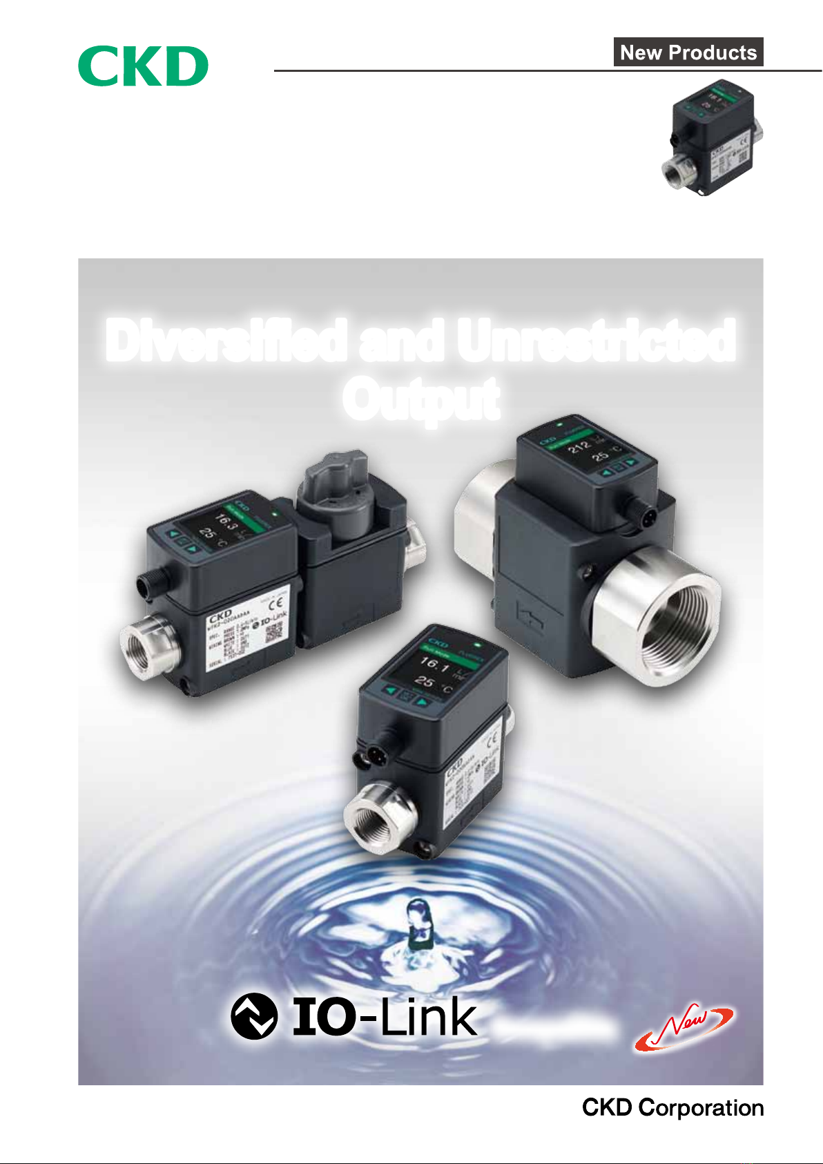
FLUEREX (Karman vortex ow rate sensor for water)
WFK2 Series
Flow rate range: 0.4 to 5, 1.6 to 20, 4 to 50, 8 to 100, 20 to 250 L/min
Specications
Descriptions WFK2-005 WFK2-020 WFK2-050 WFK2-100 WFK2-250
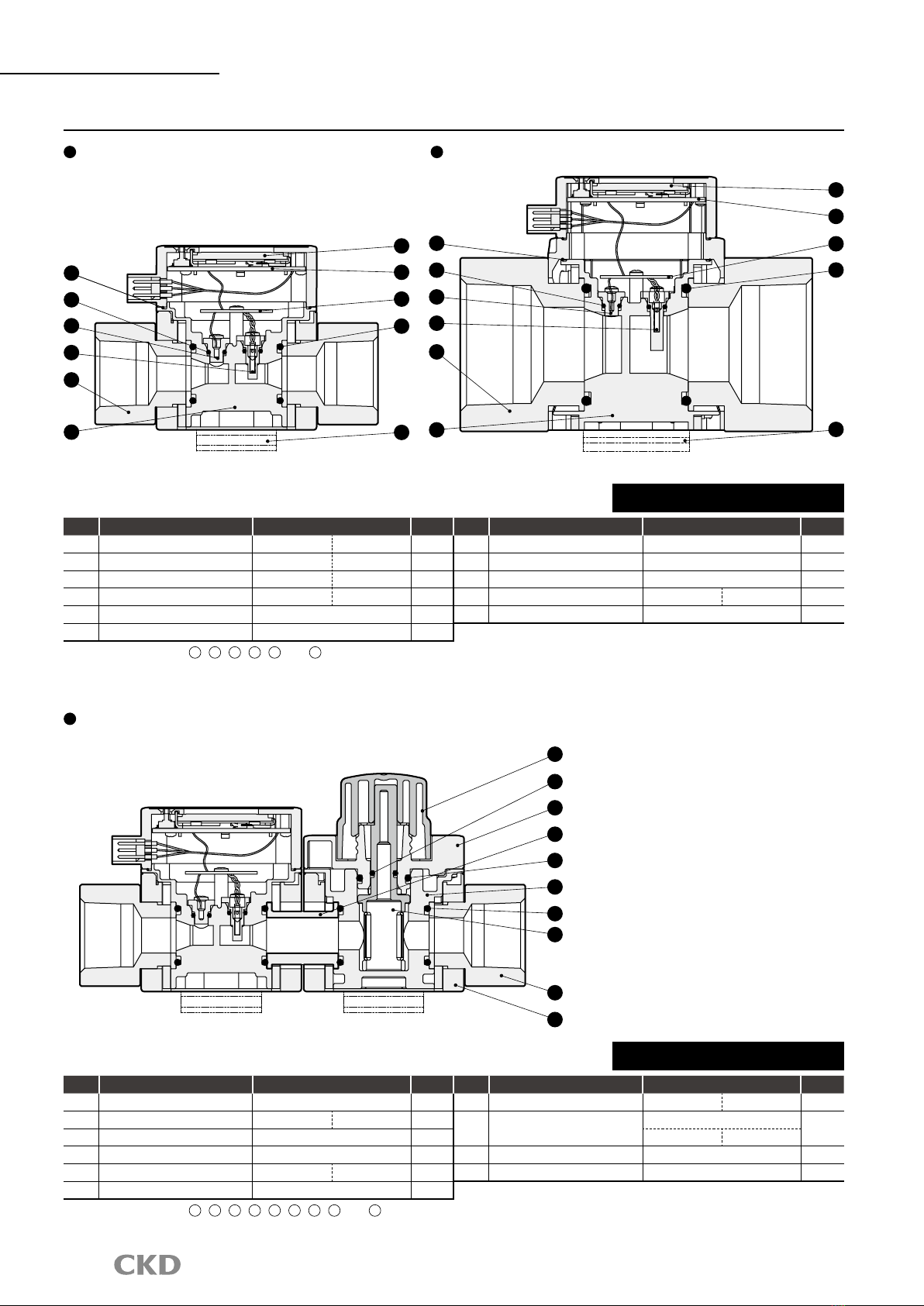
Connection
Port size Rc, G, NPT 3/8, 1/2, 3/4 1, 1 1/4, 1 1/2
Port material Stainless steel: SUS304
Working conditions
Applicable uid Pure water, industrial water
Max. working pressure MPa
1.0
Proof pressure MPa 1.5
Manual valve internal leakage mL/min
0 No manual valve settings
Manual valve allowable
back pressure
MPa 0.3 No manual valve settings
Ambient temperature °C 0 to 50 (85% RH or less, no condensation)
Fluid temperature °C 1 to 95
Flow rate
Flow rate range L/min 0.4 to 5 1.6 to 20 4 to 50 8 to 100 20 to 250
Repeatability (*1) Analog accuracy: ±2.5%F.S. Display accuracy: ±2.5%F.S. ±1 digit (min. display unit)
Temperature characteristics (*1)
±5%F.S. (base temperature 25°C, 10 to 50°C)
Low ow cut 5% of F.S.
Integrating ow range 99,999 L or 99,999 m3 (unit selectable), reset when the power is turned off.
Integrated pulse rate L/pulse
0.1, 0.5, 1 0.1, 0.5, 1, 10 0.5, 1, 10, 50 1, 10, 50, 100 10, 50, 100
Pressure loss MPa 0.07 (at F.S.) 0.05 (at F.S.) 0.05 (at F.S.) 0.05 (at F.S.) 0.03 (at F.S.)
Response time (*2) sec 0.25, 0.5, 1, 5, 10 (Initial value 1)
Temperature
Measurable temperature range
°C 0 to 100
Accuracy Less than 50: analog accuracy ±2, display accuracy ±2 ±1 digit (min. display unit 1)
50 to 100: analog accuracy ±3, display accuracy ±3 ±1 digit (min. display unit 1)
Output
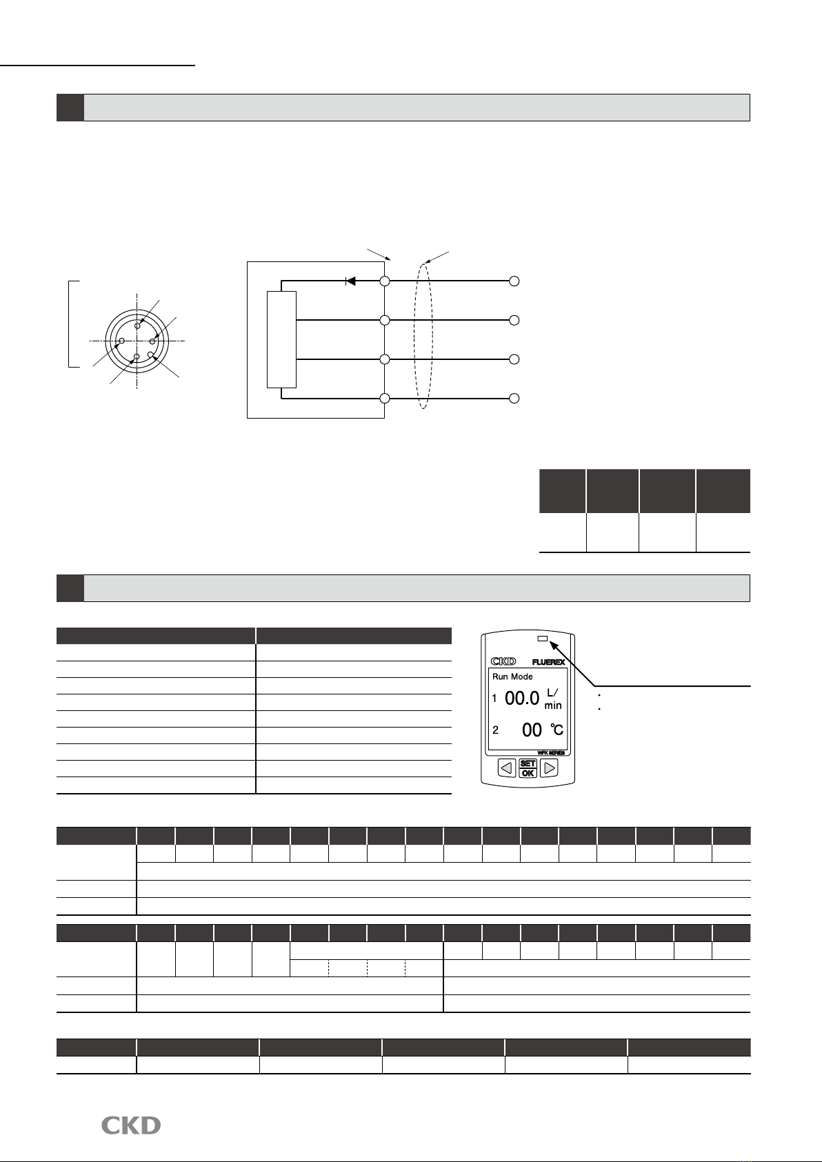
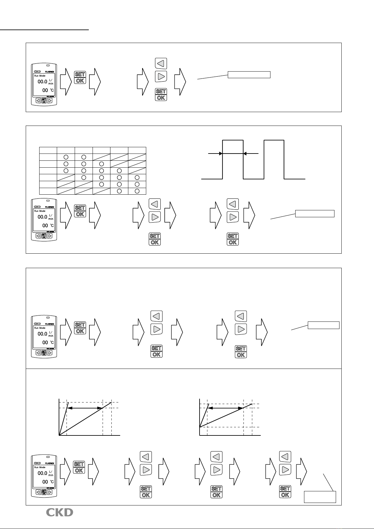
Display
Two-screen LCD display, instantaneous ow rate: 3 digits, water temperature: 2 digits, integrating ow: 5 digits, with screen rotation
Analog output (*3) Standard: 0 to 5 VDC/1 to 5 VDC, option: 4 to 20 mA DC, 0 to 10 VDC/1 to 10 VDC
Switch output NPN or PNP transistor open collector output (can be switched from settings)
Max. load current 50 mA
Max. applied voltage 30 VDC
Internal voltage drop 2.0 V or less
Power supply voltage Analog output standard: 12 to 24 VDC ±10%, analog output option: 24 VDC ±10%
Current consumption (*4) 50 mA or less
Mounting
Mounting orientation Unrestricted in vertical/horizontal direction
Straight piping section None IN side: 10 D, OUT side: 5 D
Degree of protection IP65 or equiv.
Weight g
3/8 (Rc, G, NPT): approx. 320
1/2 (Rc, G, NPT): approx. 320
3/4 (Rc, G, NPT): approx. 400
1 (Rc, G, NPT): approx. 870
1 1/4 (Rc, G, NPT): approx. 1,010
1 1/2 (Rc, G, NPT): approx. 1,100
*1: Accuracy is the average value over 10 sec (for conditions not containing air bubbles). F.S. stands for full scale ow rate.
*2: The time to attain 70% of the original output after the normal ow rate (used) drops instantly to 0.
*3: Check the allowable load on the wiring method page.
*4: Current for when 24 VDC is connected, and no load is applied. The current consumption will vary depending on how the load is connected.