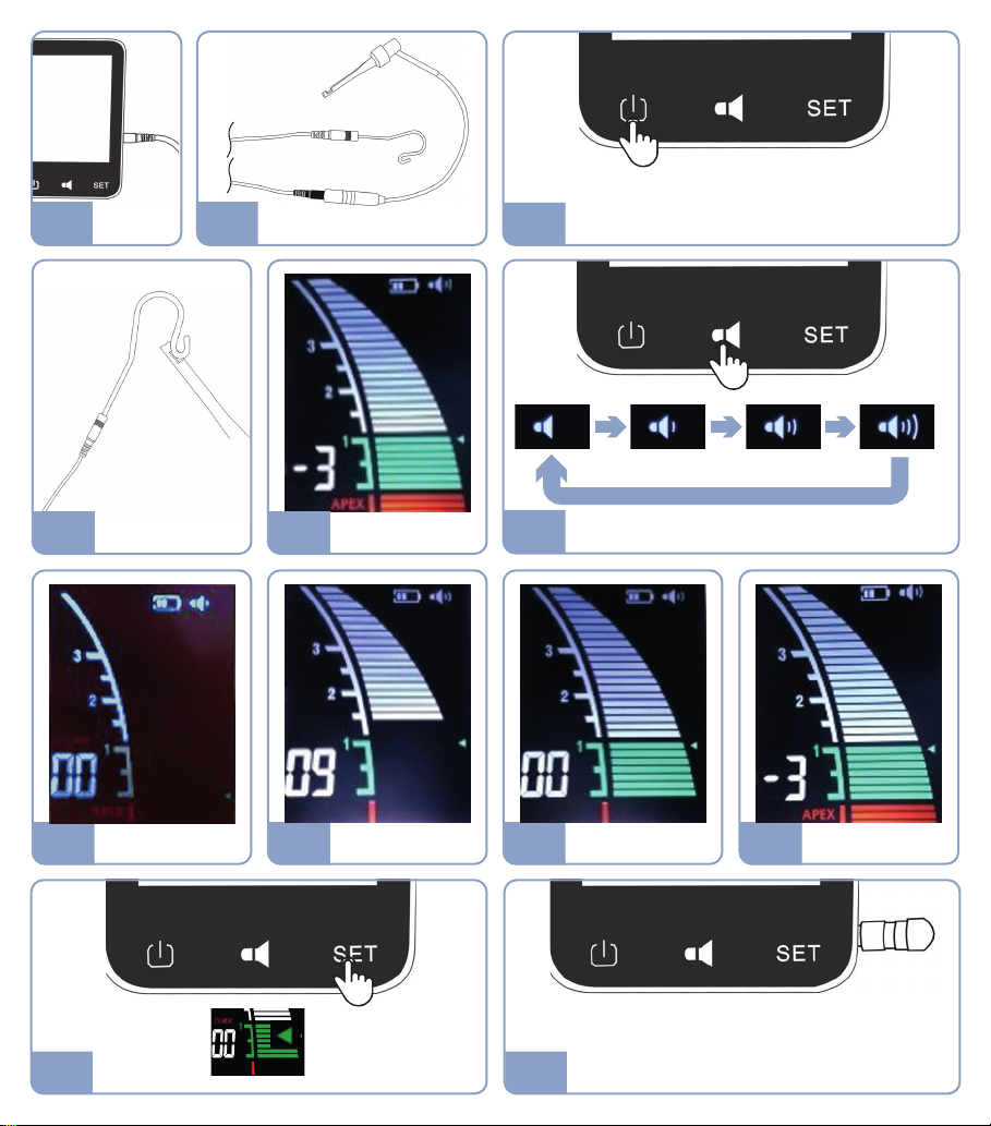
10. File location indication
9. Volume control
8. Function checking procedure
• If the system doesn’t meet these indications, check that all the parts are correctly plugged and not
damaged.
• Please plug the measuring wire into the socket in the right direction without forcing. An incorrect
connection could compromise the operation and the device accuracy.
Fig. 8.A Turn on Dual Pex by touching the power-key. Auto-shut off when unused for 10 minutes.
Fig. 8.B Create a short circuit by touching the lip hook with the metal part of the file clip.
Fig. 8.C All the horizontal strips shall be displayed on the screen along the full scale and be lighted, a discontinuous beep shall be
generated and the “APEX” label shall flash.
Fig. 10.A
The scale on the display represents the root canal. The green part corresponds to the apical foramen, between the minor apical
foramen or apical constriction (marker “1”) and the major apical foramen.
The red part is over the apex.
Fig. 10.B
The progression of the file towards the apex is showed by horizontal strips displayed along the scale.
When the file enters into the front region of the apical foramen, strips are white.
At the left of the green scale, the figure indicates the remaining number of strips before reaching the major apical foramen.
Fig. 10.C
Strips become green into the apical zone.
The minor and major apical foramens are separated by 7 strips.
“OO” is displayed when the major apical foramen is reached.
Fig. 10.D Strips become red over the apex, a rapid beep is emitted and the word “APEX” blinks.
Fig. 9 Press the Volume-key several times to adjust the sound volume (alarms and beep when touching keys).
• Open apices, drained canals, oral fluids seepage into the access cavity, root fractures / perforations or
canals filled with Gutta Percha may cause erroneous indications.
• Use only the original accessories to guarantee a right functioning and best performances.
• As the green strip number “00” corresponds to the major apical foramen and not the minor one, it is
recommended to systematically reduce the working length by 0.5-1 mm.
• Dual Pex is not a measurement device. It indicates that the file is progressively approaching the apex.
• The gingival crevicular fluid, saliva and gingival polyp will interfere with device functioning. Hence it is
recommended to correctly isolate the tooth.
• Multi-use accessories (lip hook/ file clip…) which can come in contact with the patient’s body during
operation must be sterilized by high temperature prior to each use.
Fig. 7.B Connect the file clip and the lip hook to the measuring wire.
Connect the lip hook to the patient’s lower lip and the file clip to the file that is inserted into the treated root canal. The
progression of the file into the canal in reference to the apex will be indicated on the display.
4
EN