Micron Optics os3610 User manual

I n s t a l l a t i o n G u i d e | R e v . A
Surface Mount Strain Sensor | os3610
Micron Optics Inc.
1852 Century Place NE
Atlanta, GA 30345 USA
phone 404 325 0005
fax 404 325 4082
www.micronoptics.com

Long Gage Strain Sensor | os3610
C o p y r i g h t © 2 0 1 2 M i c r o n O p t i c s , I n c .
o s 3 6 1 0 I n s t a l l a t i o n G u i d e , R e v i s i o n A 2
Introduction:
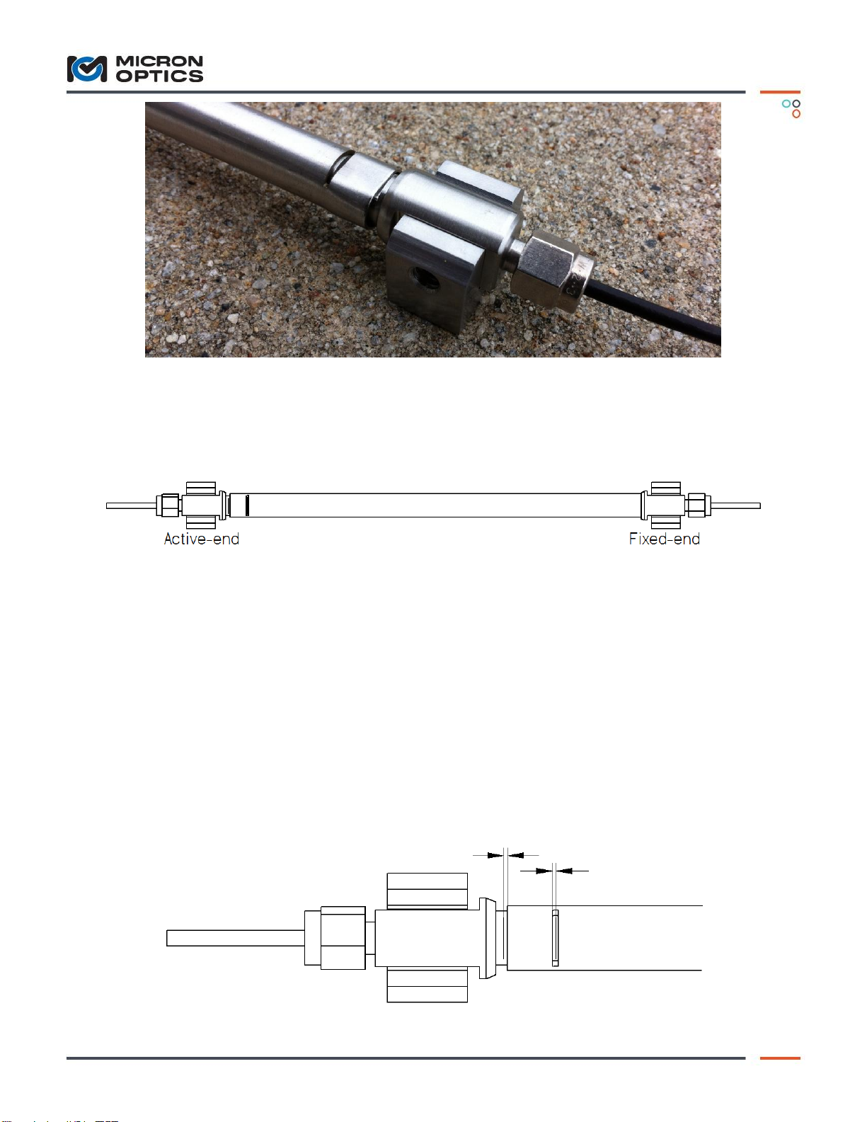
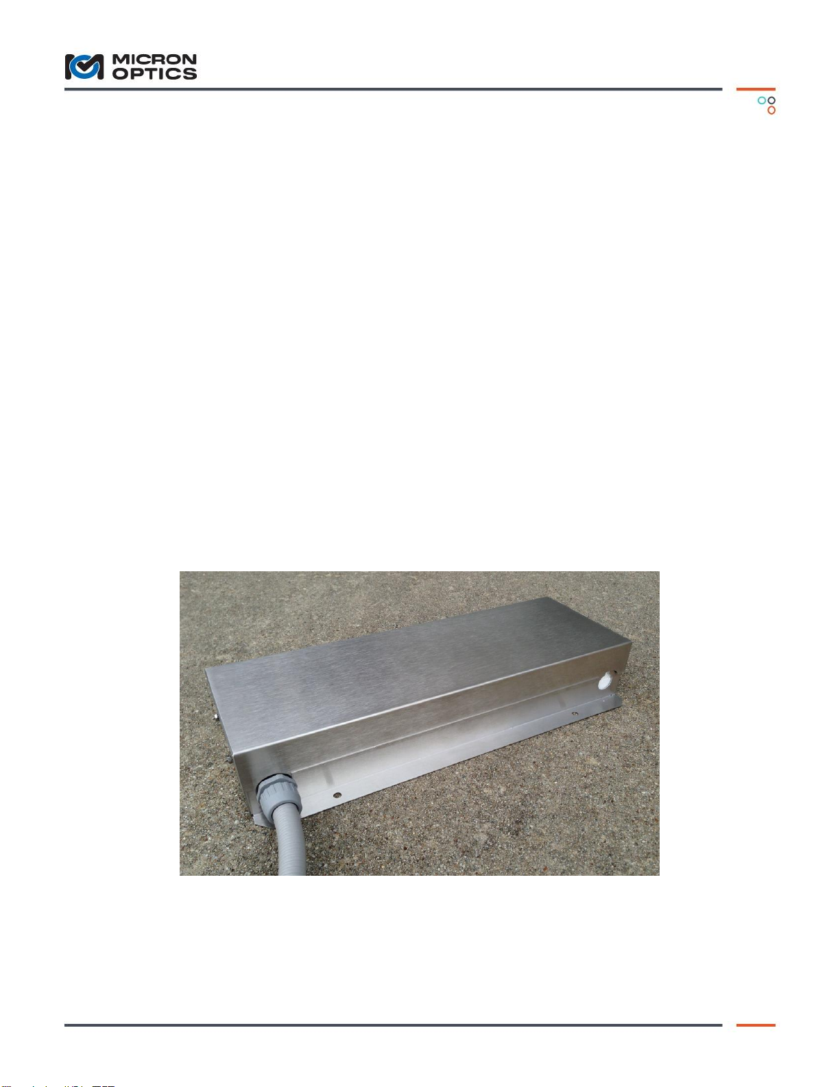
The os3610 Surface Mount Strain Sensor measures average strain over the length of the sensor
while providing integrated temperature compensation. It is based on fiber Bragg grating (FBG)
technology. The os3610 is intended exclusively for surface mounting. Each end of an os3610 is
attached to a structure via rigid brackets that are either welded, bolted, epoxied, or grouted to the
surface of a concrete, rock, steel, composite, or other structure. The os3610 strain sensor
measures the relative movement of the two mounting brackets along the axis of the sensor. It is
important that the mounting brackets be securely attached to the surface to be tested if accurate
results are to be obtained. Several installation tools are available from Micron Optics to aid in
installation. Note that tools are available for Grout-in and Bolt-on applications of gage length
25.4 cm and 100 cm.
Installation Tools:
Grout-in Drill Guide (25.4 cm)
Grout-in Drill Guide (100 cm)
Bolt-on Drill Guide (25.4 cm)
Bolt-on Drill Guide (100 cm)
Setting Bar (25.4 cm)
Setting Bar (100 cm)
Mounting To Steel (Weldable Brackets):
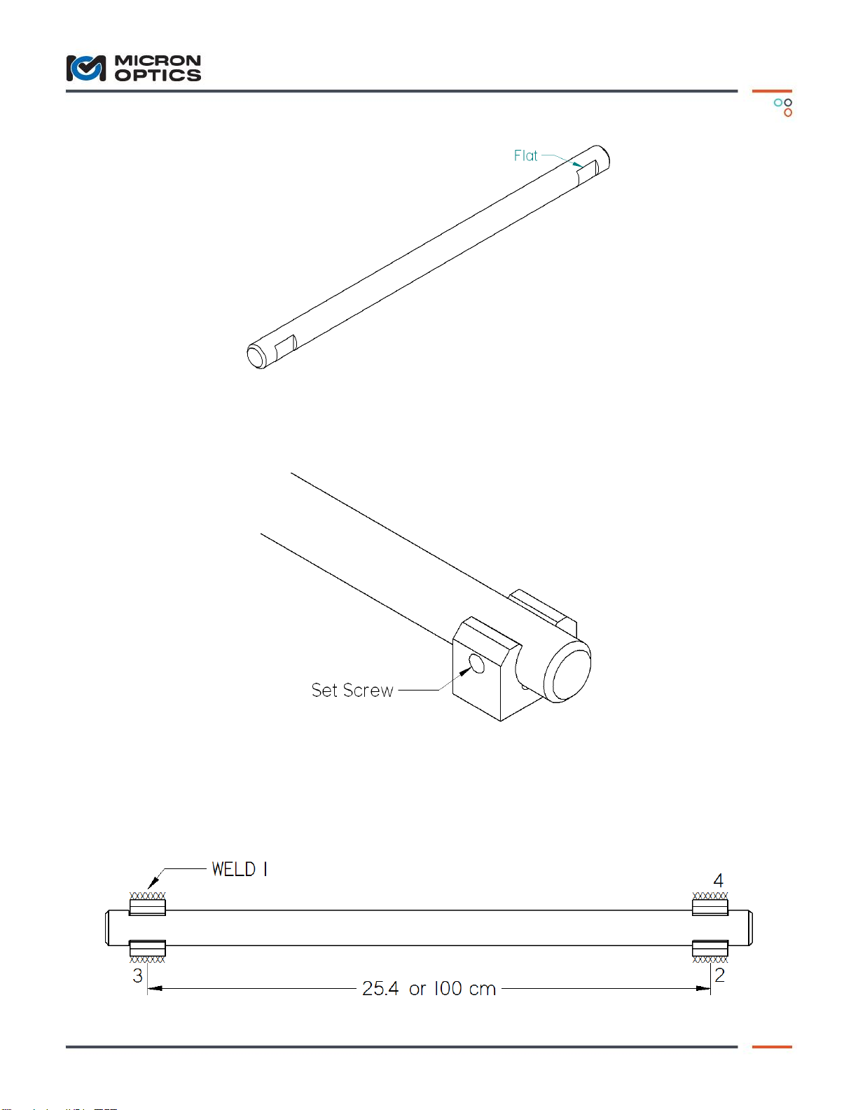
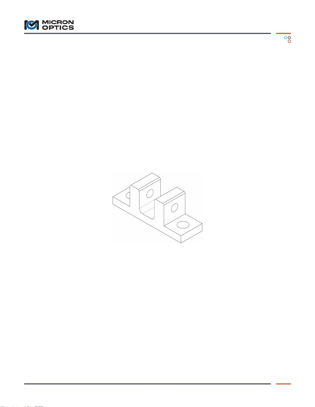
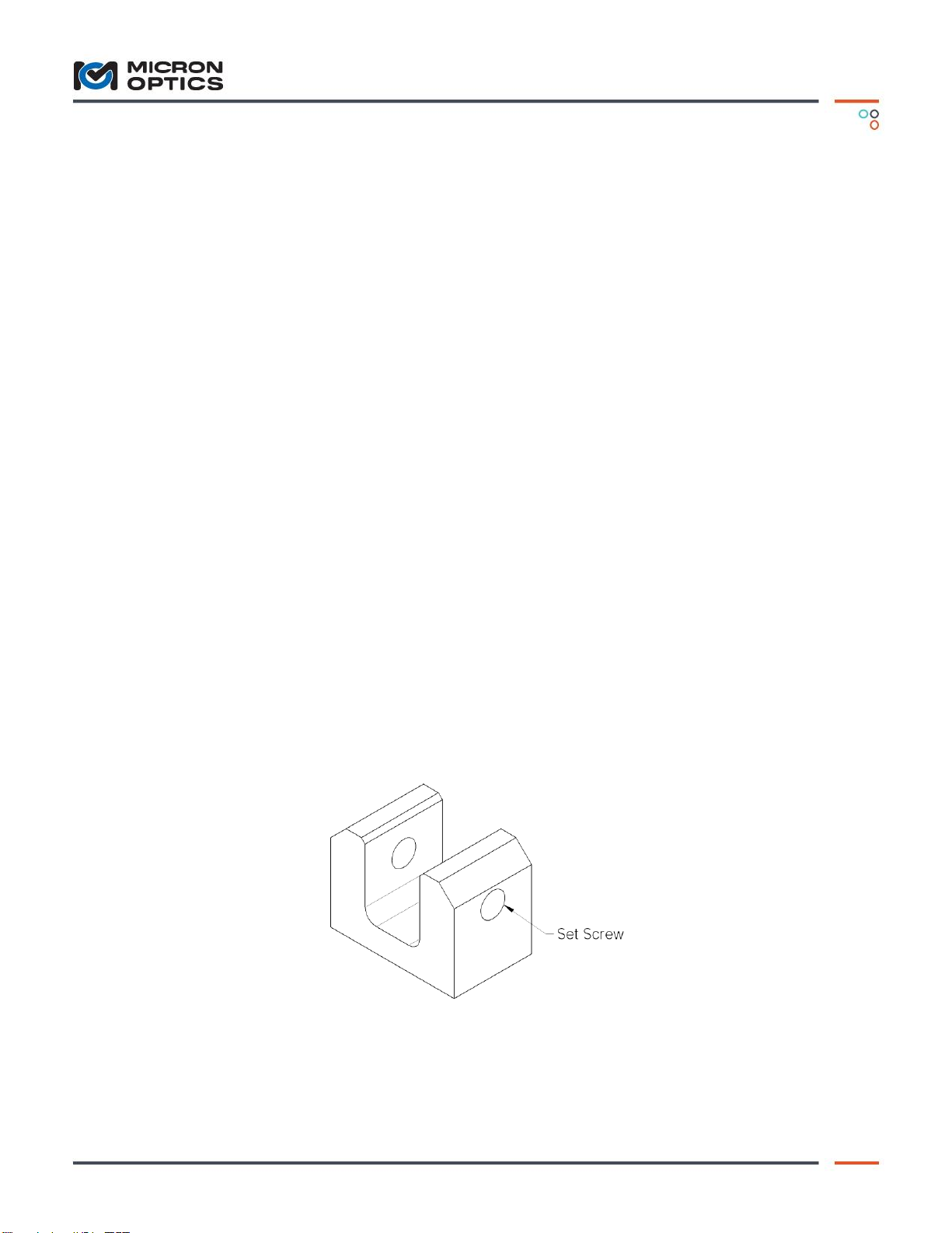
The first step in installing the os3610 strain sensor is welding the two mounting brackets to the
surface to be measured. The end brackets are made of 316 stainless steel. Each mounting bracket
has two ¼-20 set screws installed as shown in Figure 1. Use a 1/8 inch Hex-Key to tighten set
screws.
Figure 1 –Mounting Bracket
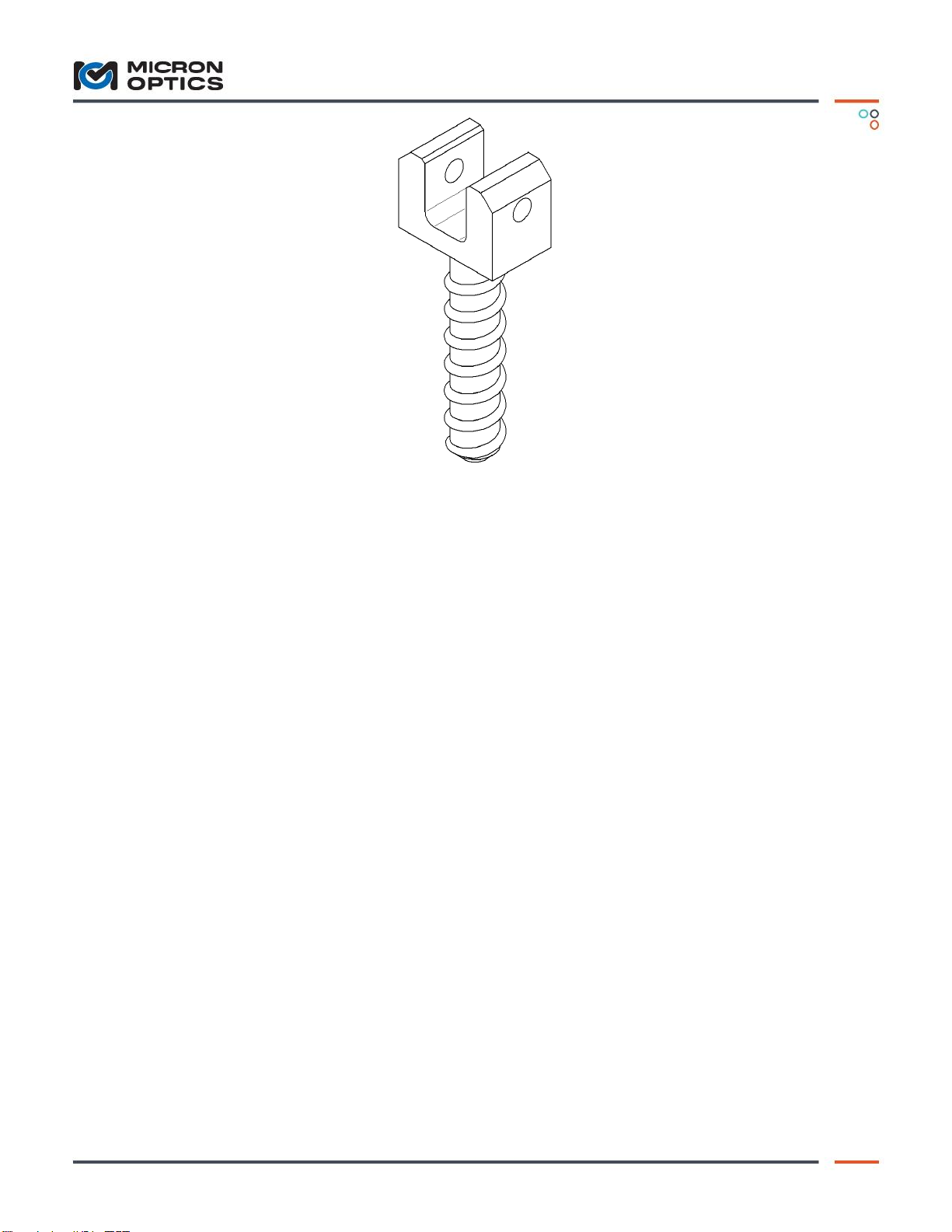
It is important that mounting brackets are properly spaced and axially aligned prior to welding. If
axial alignment is not maintained, the sensor may bind leading to reduced sensor accuracy. The
setting bar shown in Figure 2 is used to hold the mounting brackets in alignment and properly

Long Gage Strain Sensor | os3610
C o p y r i g h t © 2 0 1 2 M i c r o n O p t i c s , I n c .
o s 3 6 1 0 I n s t a l l a t i o n G u i d e , R e v i s i o n A 3
spaced during welding. The Setting Bar has flats cut into each end that properly position the end
brackets.
Figure 2 –os3610 Setting Bar
The Setting Bar is inserted in both mounting bracket and held in place with the set screws shown
in Figure 3.
Figure 3 –Close up of mounting bracket & Setting Bar
The steel surface should be cleaned to remove scale, rust, dirt, and oil. Position the Setting Bar
with the attached mounting brackets on the steel surface to be measured. Align the axis of the
Setting Bar with the axis of strain to be measured. While holding the mounting brackets firmly
against the surface, weld the edges shown in Figure 4 in the indicated sequence.

Long Gage Strain Sensor | os3610
C o p y r i g h t © 2 0 1 2 M i c r o n O p t i c s , I n c .
o s 3 6 1 0 I n s t a l l a t i o n G u i d e , R e v i s i o n A 4
Figure 4 –Weld Location / Sequence
Allow the weld to cool and remove the Setting Bar. Clean off welding slag and inspect weld.
Mounting To Steel (Bold-On Brackets):
An alternative mounting bracket shown in Figure 5 is available as an option that can be fastened
to the test specimen using two ¼-20 screws. Button head cap screws are recommended to allow
clearance for set screw Hex-Key. It is important that mounting brackets are properly spaced and
axially aligned prior to mounting. If axial alignment is not maintained, the sensor may bind
leading to reduced sensor accuracy. The Setting Bar shown in Figure 2 is available to hold the
mounting brackets in alignment and properly spaced while the mounting holes are transferred to
the specimen surface. The Setting Bar has flats cut into each end that properly position the end
brackets. Alternatively, the Bolt-on drill guide listed in the “Installation Tools” section can be
used. To use the Drill Guide, securely clamp it to the surface. Drill the four holes using the Drill
Guide to guide the drill bit. After both brackets are bolted securely to the surface, check the
alignment by verifying that the Setting Bar will drop into the brackets.
Figure 5 –Bolt-On Mounting Bracket
Mounting To Concrete:
The concrete mounting brackets shown in Figure 6 may be attached to concrete by inserting the
concrete mounting bracket stud into a drilled hole and securing with anchoring cement or epoxy.

Long Gage Strain Sensor | os3610
C o p y r i g h t © 2 0 1 2 M i c r o n O p t i c s , I n c .
o s 3 6 1 0 I n s t a l l a t i o n G u i d e , R e v i s i o n A 5
Figure 6 –Concrete Mounting Bracket
Prepare the test surface by drilling two ½ inch [13mm] diameter holes properly spaced. To
maintain hole spacing and alignment it is necessary to use the Grout-in Drill Guide listed in the
“Installation Tools”section. The distance between the holes is determined by the gage length
purchased. The distance between the holes is equal to the gage length. Standard gage lengths are
25.4 cm and 100 cm. The holes should be a minimum of 3 ½ inches [64 mm] deep. To use the
Drill Guide, clamp it to the surface. Place hammer-drill in hole on one end of drill guide and drill
hole. Place 1/2 inch round bar through drill guide into hole just drilled. This will help hold Drill
Guide in place while second hole is drilled. Now Place hammer-drill in hole on other end of Drill
Guide and drill hole. Clean out holes with vacuum or compressed air. Attach the mounting
brackets to the Setting Bar as shown in Figure 3 to maintain proper alignment and spacing. Grout
the mounting bracket studs into place in the drilled holes using an anchoring cement or high
strength epoxy. Allow the grout or epoxy to cure before removing the Setting Bar.
Sensor Installation:
Once the mounting brackets are attached to the surface to be studied, the sensor may be set in
place and pre-tension adjusted. An interrogation unit attached to the sensor may be helpful in
adjusting pre-tension.
Notice that one end of the sensor has two windows cut into the steel tube (Active-end). The other
end has a hex crimp (Fixed-end). Set the sensor in place by placing by aligning the sensor flats
into the mounting brackets as shown in Figure 7.
Other Micron Optics Accessories manuals