micronAir MICROMISER 12 Service manual

MICROMISER 12 & 16
ATOMISERS
AND
CONTROLLER
Operator's Handbook
and
Parts Catalogue
Micron Sprayers Limited
Bromyard Industrial Estate
Bromyard
Herefordshire HR7 4HS
United Kingdom
Telephone: +44 (0) 1885 482397
Fax: +44 (0) 1885 483043
Web site: www.micron.co.uk
Iss 4W
11/2021

TABLE OF CONTENTS
1. INTRODUCTION...........................................................................................1
2. SPECIFICATION...........................................................................................2
2.1. Atomiser........................................................................................2
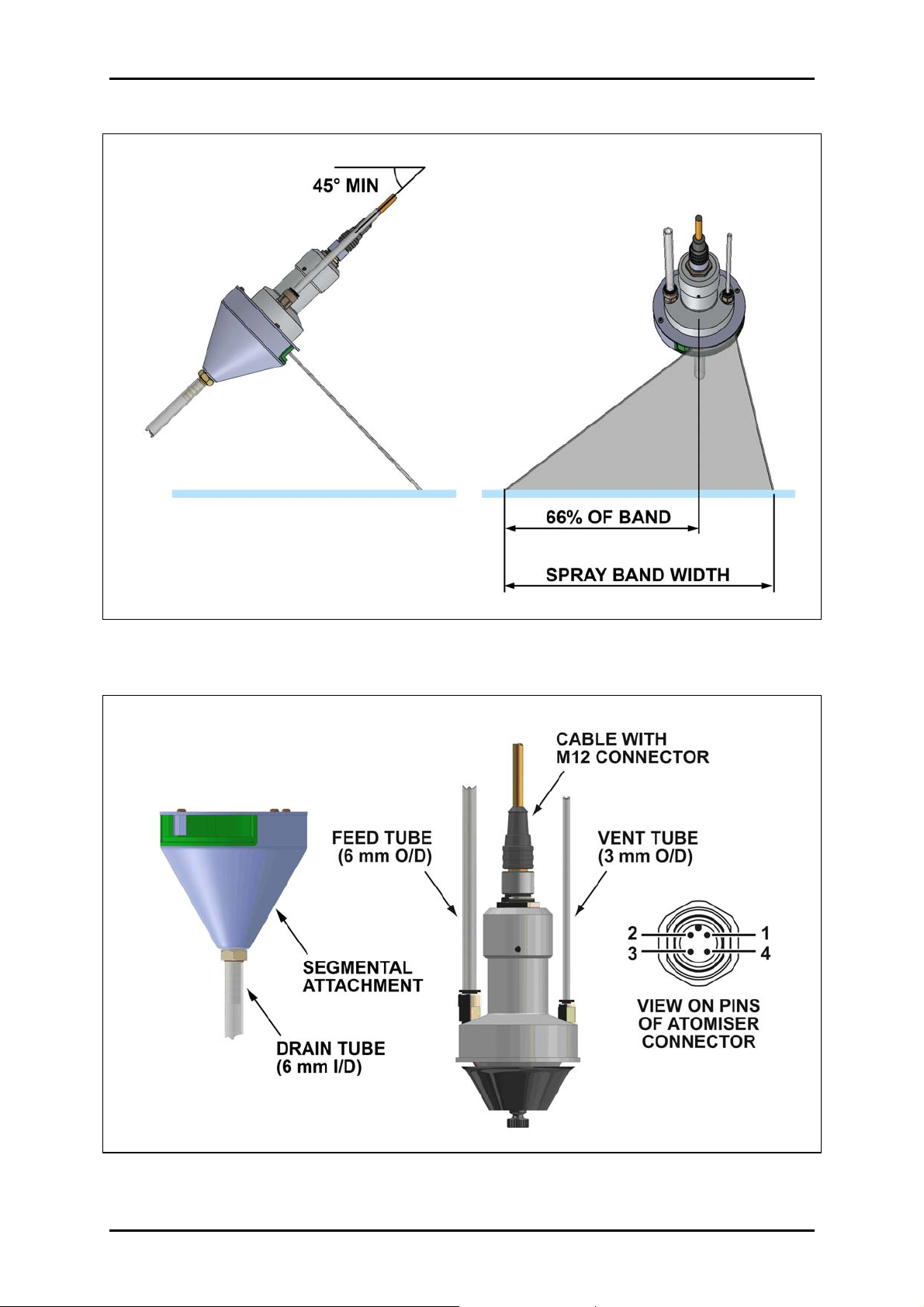
2.2. Segmental Attachment..................................................................2
2.3. Controller ......................................................................................3
3. INSTALLATION.............................................................................................5
3.1. Atomiser........................................................................................5
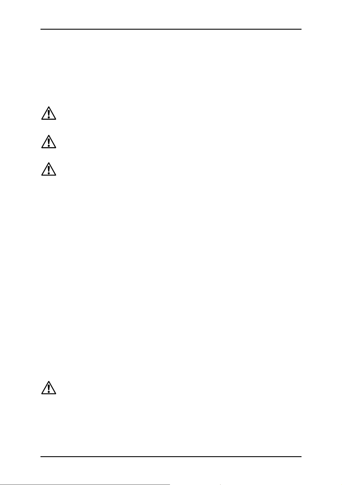
3.1.1. Mounting – Basic Atomiser ...................................................5
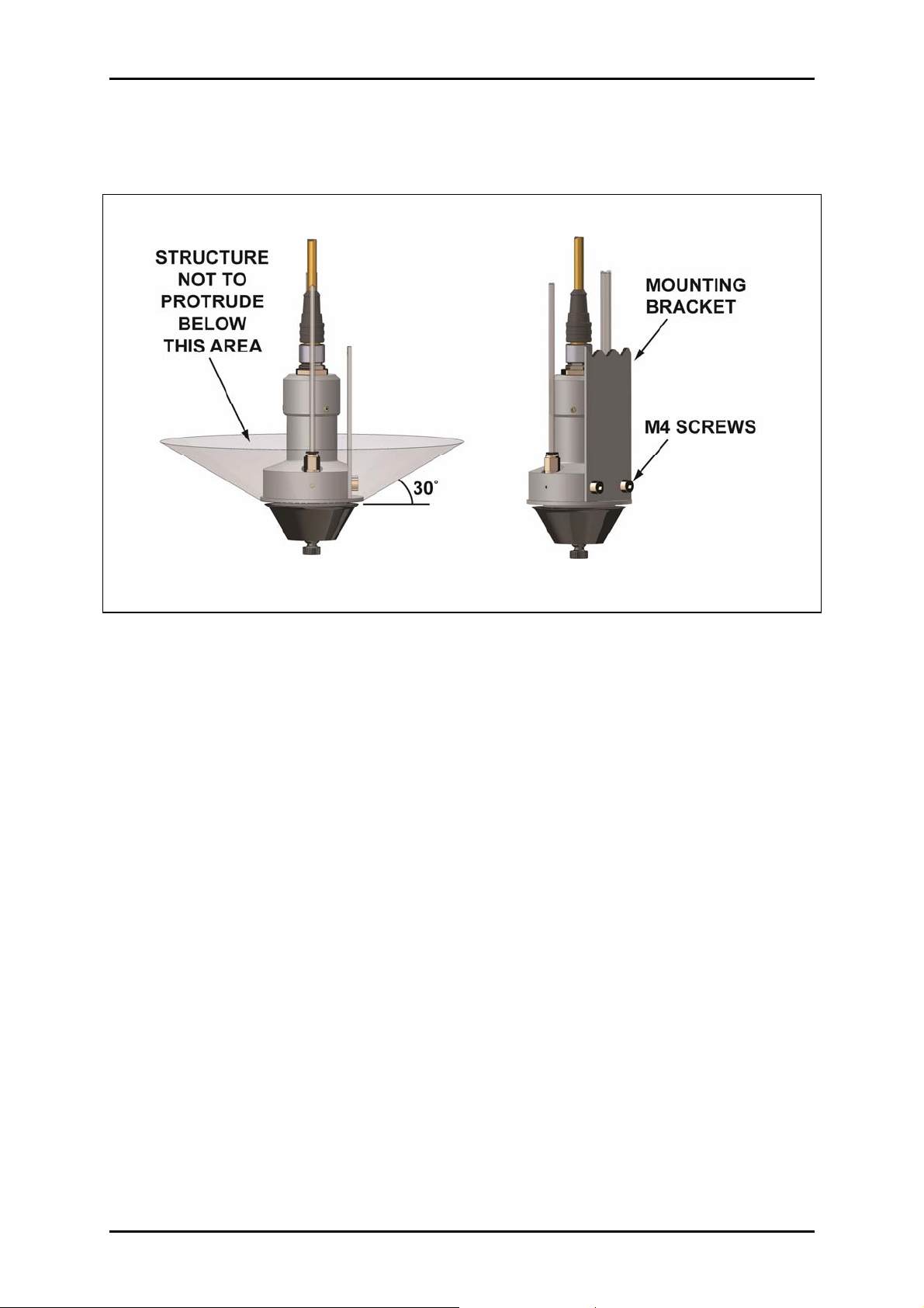
3.1.2. Mounting – with Segmental Attachment................................6
3.2. Liquid Feed ...................................................................................8
3.3. Liquid Drain...................................................................................9
3.4. Motor Venting................................................................................9
3.5. Electrical Connections.................................................................10
3.5.1. Use with Micronair Controller ..............................................10
3.5.2. Use with External Power Supply .........................................10
3.5.3. Atomiser Speed Control (Micromiser 12 Only)....................13
3.5.4. Atomiser Speed Output.......................................................14
3.6. Controller ....................................................................................15
3.6.1. Mounting .............................................................................15
3.6.2. Electrical Connections.........................................................16
3.6.2.1. Power Supply.................................................................16
3.6.2.2. Atomiser ........................................................................17
3.6.2.3. Atomiser Speed Control Input........................................17
3.6.2.4. Atomiser Enable Input ...................................................17
3.6.2.5. Atomiser Speed Control Output .....................................17
3.6.2.6. Atomiser Run Output .....................................................18
3.6.2.7. Atomiser RPM Output....................................................18
3.6.2.8. Control Ground ..............................................................18
4. OPERATION ...............................................................................................19
4.1. Atomiser......................................................................................19
4.2. Controller (Micromiser 12 Only) ..................................................19
5. CALIBRATION ............................................................................................20
5.1. Flow Rate....................................................................................20
5.2. Spray Droplet Size ......................................................................21
6. MAINTENANCE ..........................................................................................23
6.1. Routine maintenance – Atomiser ................................................23
6.2. Routine maintenance – Controller...............................................24
6.3. Fault Finding ...............................................................................25
7. PARTS LISTS .............................................................................................27
7.1. Micromiser Atomiser ...................................................................27
7.2. Controller ....................................................................................27
7.3. Cable Assembly ..........................................................................27
7.4. Segmental Attachment................................................................28

USE OF WARNING SYMBOLS
There are two safety warning symbols used throughout this handbook:
Danger related to electricity – warns of high voltage which can cause
physical injury or death and/or damage to the equipment.
General danger – warns about conditions, other than those related to
electricity, which can result in physical injury and/or damage to the equipment.

MICRONAIR MICROMISER ATOMISER & CONTROLLER
1. INTRODUCTION
Micronair Micromiser atomisers are designed specifically to spray a wide range of
liquids in droplets of precisely controlled size. Applications include treatment of
seeds and agricultural products, humidification, evaporative cooling, spraying of
odour control products and any industrial processes requiring precision spray
application.
Spray droplets are produced by a rotating toothed disc. Droplet size is determined
by the rotational speed of the disc, which is driven by a low voltage brushless motor
for maximum reliability.
Unlike hydraulic spray nozzles, the atomiser does not require a high liquid pressure
to operate and there are no small internal orifices to block. This allows the atomiser
to handle viscous materials and liquids with a high solids content.
The atomiser can operate at flow rates of up to 300 ml/min, with the minimum flow
rate determined only by the liquid delivery system used.
The brushless motor has integrated drive electronics and requires only a 24 V DC
supply to operate. A pulse output is provided for the measurement of disc speed or
monitoring of atomiser performance.
The atomiser is available in two versions:
Micromiser 12 with rotational speed variable over the range of 1,500 – 12,000 RPM
to produce spray droplets of 60 – 300 µm VMD. This atomiser can be used for spray
application on surfaces, in industrial processes etc. The atomiser motor incorporates
closed-loop speed control to ensure constant rotational speed regardless of liquid
flow rate.
The Micromiser 12 can be fitted with an optional segmental attachment that restricts
the spray droplets from the disc to a fan-shaped pattern for application across a
band for treatment of surfaces, conveyors etc. The remaining spray liquid is
collected and recycled to the supply.
Micromiser 16 with a fixed rotational speed of 15,000 – 16,000 RPM to produce
small spray droplets of 45 – 60 µm VMD for humidification, evaporative cooling,
application of odour control products etc.
An optional DIN rail mounted power supply and control module is available for use
with the Micromiser 12 atomiser. This has a 110/240 V AC/DC input and
incorporates a speed controller to enable the atomiser to be set to be set to operate
at the required speed regardless of liquid flow rate. The speed can be set either by a
control on the front panel or by an external potentiometer or control input. The
module has an input for an external run/stop command and provides outputs for
motor status and disc rotational speed.

2
MICRONAIR MICROMISER 12 & 16 ATOMISERS & CONTROLLER
2. SPECIFICATION
2.1. Atomiser
Dimensions: Length 105 mm (including atomiser disc but excluding
connector), diameter 58 mm (max), 32 mm (motor
housing)
Weight: 240 g
Mounting: By two M4 tapped holes
Liquid feed connection: Push-in fitting for 6 mm O/D rigid plastic tube
Vent connection: Push-in fitting for 3 mm O/D rigid plastic tube
Electrical connection: 4 pin M12 sealed connector (A-coding)
Environmental protection: IP65 (with motor vent tube connected)
Ambient temperature: -10 – +40 ºC nominal (minimum temperature must not
be below freezing point of liquid being sprayed)
Input voltage: 24 V DC
Power consumption: 1 – 10 W (dependant upon disc speed and liquid flow
rate)
Motor rating: Continuous
Disc speed: Micromiser 12: adjustable 1,500 – 12,000 RPM
Micromiser 16: fixed 15,000 – 16,000 RPM
Speed output: 5 V pulse output (one pulse/disc revolution)
Spray droplet size: Micromiser 12: 60 – 300 µm VMD
Micromiser 16: 45 – 60 μm VMD
(dependant upon disc speed & liquid properties)
Liquid flow rate: 0 – 300 ml/minute inlet flow
2.2. Segmental Attachment
Dimensions: Diameter 75 mm max, length 70 mm from flange of
atomiser body (excluding hose connector)
Weight: 30 g
Drain outlet connection: Hosetail for 6 mm I/D flexible tube
Spray segment: 60˚included angle
Liquid in spray segment: 25% (remainder drained from outlet)

3
MICRONAIR MICROMISER 12 & 16 ATOMISERS & CONTROLLER
2.3. Controller
Dimensions: Height 75 mm, width 55 mm, depth 110 mm (excluding
connector)
Weight: 300 g
Mounting: DIN 46 227 (DIN EN 50 022) rail or by two 4 mm
mounting holes in base
Environmental protection: IP20
Ambient temperature: -10 – +40º C (non condensing)
Input voltage: 85 – 260 V 50 – 60 Hz AC
120 – 370 V DC
Power consumption: 15 W max (dependant upon disc speed and liquid flow
rate)
Atomiser speed range: Micromiser 12 only: 1,500 – 12,000 RPM
Electrical connections: Atomiser – 4 pin M12 connector (A polarisation)
Power and control inputs/outputs – screw terminals
Control inputs: Remote motor speed (DC voltage)
Motor inhibit/enable (pull low to inhibit)
Outputs: Motor status (NPN transistor, pulled low when running)
Disc RPM (DC voltage)
Front panel: Speed control knob
LED indicators (green) for power, motor enabled and
motor running

4
MICRONAIR MICROMISER 12 & 16 ATOMISERS & CONTROLLER
Fig 1. – Micromiser Atomiser
Fig 2. – Micromiser 12 with Segmental Attachment

5
MICRONAIR MICROMISER 12 & 16 ATOMISERS & CONTROLLER
3. INSTALLATION
3.1. Atomiser
The Micronair Micromiser atomiser has a wide range of uses and the specific details
of the installation will depend upon the application and the operating environment.
The following sections are provided for general guidance only.
It is the responsibility of the installer and/or end user to ensure that the
installation of the atomiser and all associated wiring, pipework and equipment
complies with all applicable standards and statutory requirements.
It is the responsibility of the installer and/or end user to ensure that water or
other spray liquids are handled and/or treated so as to eliminate the possibility
of the distribution of bacterial or other infections in spray droplets.
The atomiser must NOT be installed in an explosive atmosphere. The
atomiser must NOT be used to spray liquids with a flash point of 40º C (104º
F) or below or in any situation where the spray liquid or spray droplets could
cause a fire, explosion or other hazard.
The atomiser must be fitted to a suitable mounting bracket supplied by the installer.
The design of the bracket will be determined by the adjacent structure, but the
following general points must be observed:
The atomiser should be attached to the mounting bracket with two M4 screws in
the tapped holes in the side of the atomiser housing (25 mm between hole
centres) as shown in Fig. 3. M4 x 12 mm stainless steel cap head screws are
supplied with the atomiser and these are suitable for a bracket with a thickness
of 2 – 6 mm. If alternative screws are used these should also be stainless
steel.
The bracket must be sufficiently rigid to avoid excessive vibration when the
atomiser or any nearby equipment is operating.
The design of the installation should allow the atomiser and its rotating disc to
be easily removed for cleaning and servicing.
3.1.1. Mounting – Basic Atomiser
When used without the segmental attachment the atomiser is designed to be
mounted with the disc downwards and with the axis of the disc within ±30º of the
vertical.
The toothed edge of the rotating disc of the atomiser is sharp and can cause
serious injury if touched whilst it is rotating. The atomiser must be installed in
a position where it cannot be touched or come into contact with clothing, hair
etc during operation (either by mounting at a height of 3 m or more above
floor level or in an enclosed space). If the atomiser is installed in an enclosed
space all access doors, panels etc must be fitted with electrical interlocks to
disconnect the power supply to the atomiser when opened.

6
MICRONAIR MICROMISER 12 & 16 ATOMISERS & CONTROLLER
The bracket and any adjoining structure should not protrude below the area shown in
Fig. 3. This is to minimise contamination by spray droplets from the rotating disc.
Fig. 3 – Mounting of Atomiser
3.1.2. Mounting – With Segmental Attachment
If not already fitted, the segmental attachment must be mounted on the atomiser by
means of its securing ring and the three self-tapping screws supplied. The 6 mm
inlet fitting and M4 securing screws must be removed from the atomiser body before
fitting the securing ring and be replaced afterwards.
When used with the segmental attachment the atomiser must be mounted above the
surface to be sprayed with the axis of the disc inclined at an angle of at least 45º
below the horizontal as shown in Fig. 4. This is to allow spray liquid collected within
the conical body to flow into the drain tube.
The segmental attachment is mounted on the body of the atomiser by means of a
securing ring and three self-tapping screws. The attachment can be rotated on the
atomiser after slackening the screws to adjust the trajectory of the segmental spray
pattern. The screws must be re-tightened after adjustment.
The width of the band sprayed will depend upon the distance of the atomiser from
the surface as measured along the trajectory of the spray droplets.
In order to ensure even spray coverage across a surface the atomiser should be
mounted above a point corresponding to about 66% of the width of the spray band
as viewed on the motor end of the atomiser – see Fig. 4. The segmental attachment
should be rotated to achieve the correct lateral position of the spray band.

7
MICRONAIR MICROMISER 12 & 16 ATOMISERS & CONTROLLER
Fig. 4 – Mounting of Atomiser with Segmental Attachment
Fig. 5 – Connections to Atomiser

8
MICRONAIR MICROMISER 12 & 16 ATOMISERS & CONTROLLER
3.2. Liquid Feed
The liquid feed to the atomiser is by a tube connected to the inlet fitting at the top
face of the housing as shown in Fig. 5. The standard fitting supplied with the
atomiser is a push-fit type that accepts a 6 mm outside diameter flexible tube. If
required, this fitting can be replaced with an alternative type with a M5 male thread to
screw into the atomiser housing.
As there are no small orifices in the atomiser, the liquid pressure required at the
atomiser inlet is very low – see Graph 1.
0 100 200 300
FLOW (ml/MIN)
0
50
100
150
200
250
300
350
INLET PRESSURE (mm HEAD OF WATER)
PRESSURE MEASURED
AT INLET WITH WATER
Graph 1 – Inlet Pressure vs Flow Rate
Liquid can be fed to the atomiser either by gravity from a header tank or by means of
a pump. If a gravity feed or pressurised supply is used the installer must provide a
suitable flow control (eg a fixed orifice or a needle valve). If a flow restrictor is used it
is recommended that the pressure on the inlet side of the restrictor is kept as low as
possible to avoid the need for a small orifice and to minimise the risk of blockage.
Alternatively, a positive displacement dosing pump can be used without a flow
restrictor.

9
MICRONAIR MICROMISER 12 & 16 ATOMISERS & CONTROLLER
3.3. Liquid Drain
If the atomiser is fitted with a segmental attachment the excess liquid collected within
the conical housing drains from the 6 mm diameter hose fitting at the bottom of the
cone. This liquid must be allowed to flow by gravity either back into the main
reservoir or into a collecting tank from which it can be recycled.
3.4. Motor Venting
In many applications (evaporative cooling, humidification etc) the atomiser will
operate in a high humidity environment. In order to avoid condensation inside the
motor, the atomiser is fitted with a vent port that must be connected to a tube that
can supply air from an area of low humidity (eg outside the air handling unit or other
enclosure) – see Fig. 5. The standard vent fitting supplied with the atomiser is a
push-fit type that accepts a 3 mm outside diameter flexible tube. If required, this
fitting can be replaced with an alternative type with a M5 male thread to screw into
the atomiser housing.
When operating at 5,000 RPM or above, the rotation of the atomiser disc creates a
small negative pressure inside the motor housing and this is sufficient to draw air into
the vent port provided that the length of the vent tube does not exceed 2 m. In this
case, the tube must run upwards throughout its length so as to avoid any loops that
could trap moisture – see Fig. 6.
Fig. 6 – Orientation of Atomiser Vent Tube

10
MICRONAIR MICROMISER 12 & 16 ATOMISERS & CONTROLLER
If the atomiser is operated in a high humidity environment at less than 5,000 RPM or
if it is not possible to install a vent tube leading to an area of low humidity, the vent
should be purged with a supply of dry compressed air or inert gas. A suitable
pressure and/or flow regulator should be provided to limit the flow rate to
approximately 10 – 100 cc/min.
It is the responsibility of the installer to provide adequate venting for the
atomiser. Micron Sprayers Ltd cannot accept any liability for damage to the
motor resulting from condensation due to inadequate venting.
3.5. Electrical Connections
The atomiser is fitted with a sealed 4 pin male M12 connector (A-coding). Pin
numbers are as shown in Fig. 5.
It is recommended that the cable with moulded connector supplied with the atomiser
is used to connect it to the remote power supply or controller so as to prevent
moisture ingress. If an alternative re-wireable connector is used it must be filled with
non-corrosive silicone rubber compound.
The cable used to connect the atomiser to the power supply or controller should
have a minimum conductor size of 0.33 mm2(22 AWG) for a length of 10 m or less
or 0.5 mm2(20 AWG) for longer lengths.
3.5.1. Use with Micronair Controller
If a Micromiser 12 atomiser is to be used in conjunction with the Micronair controller
(P/N EX7482), the 4 pin connector on the atomiser must be connected to the 4 pin
connector on the controller. It is recommended that a ready-made cable with
moulded connectors should be used. If re-wireable connectors are used, the
corresponding pin numbers should be connected together (1 – 1, 2 – 2, 3 – 3 & 4 –
4) with pin assignments as shown in Fig. 5.
See section 3.6 for further details of the installation of the controller.
3.5.2. Use with External Power Supply
A Micromiser 12 atomiser can be operated from a 24 V DC power supply instead of
the Micronair controller and a Micromiser 16 atomiser must always be operated from
a 24 V DC supply. This supply must be provided by the installer and the minimum
requirements are:
Output voltage: 24 V.
Current: 0.75 A minimum continuous.
Current limit: Internal current limit, fuse or circuit breaker to limit fault
current to 1 A maximum.
Ripple: 100 mV P/P maximum at max load.

11
MICRONAIR MICROMISER 12 & 16 ATOMISERS & CONTROLLER
Graph 2 shows the relationship between current consumption, atomiser rotational
speed and liquid flow rate for the Micromiser 12. Graph 3 shows the relationship
between current consumption and liquid flow rate for the Micromiser 16 when
operated from a 24 V supply.
If a Micromiser 12 atomiser is operated from a power supply provided by the installer
it is necessary to use an external variable or fixed resistor to adjust the speed of the
disc. See section 3.5.2 for details.
Connections to the atomiser are as follows (see Fig. 5 for numbering of connector
pins):
Pin 1 (brown wire in standard moulded M12 cable): +24 V DC supply.
Pin 2 (white wire in standard moulded M12 cable): speed measurement pulse
output if required, must be left open circuit otherwise.
Pin 3 (blue wire in standard moulded M12 cable): power supply ground (0 V)
and ground side of speed control resistor (Micromiser 12 only).
Pin 4 (black wire in standard moulded M12 cable): speed control resistor
(Micromiser 12 only). Must be left open circuit for Micromiser 16.
Important: verify polarity before connecting the atomiser. Reverse polarity will
destroy the atomiser motor.
Pin 2 MUST be left open circuit unless used for speed measurement – see
section 3.5.4). Connecting this wire to ground or a supply voltage could
destroy the atomiser motor.
Pin 4 MUST ONLY be connected to a resistor to control the speed of a
Micromiser 12 atomiser. Connecting this wire to a supply voltage could
destroy the atomiser motor. Pin 4 MUST be left open circuit for a Micromiser
16 atomiser.
It is the responsibility of the installer to ensure that the power supply is
installed and connected in accordance with all applicable standards and
statutory requirements. The installer is also responsible for ensuring that the
complete installation (atomiser, power supply and associated wiring) complies
with the applicable standards for electromagnetic compatibility (EMC).

12
MICRONAIR MICROMISER 12 & 16 ATOMISERS & CONTROLLER
1000 2000 3000 4000 5000 6000 7000 8000 9000 10000 11000 12000
ATOMISER RPM
0
50
100
150
200
250
300
350
400
450
500
MOTOR CURRENT (mA)
200 ml/min
300 ml/min
100 ml/min
Dry
Graph 2 – Current Consumption of Micromiser 12 vs Atomiser RPM and Flow Rate
0 100 200 300
FLOW (ml/MIN)
0
100
200
300
400
500
MOTOR CURRENT (mA)
Graph 3 – Current Consumption of Micromiser 16 vs Flow Rate at 24 V Input

13
MICRONAIR MICROMISER 12 & 16 ATOMISERS & CONTROLLER
3.5.3. Atomiser Speed Control (Micromiser 12 Only)
The speed the Micromiser 12 atomiser is determined by the voltage on pin 4 of the
motor connector. This pin is pulled up to the internal +5 V supply of the motor
controller and an external resistor between pin 4 and ground forms a potential divider
to set the control voltage. Fig. 7 shows a simplified schematic of the control input.
The external speed control resistor can be either an adjustable potentiometer or a
fixed resistor if the atomiser is always to operate at a set speed. Graph 4 shows the
relationship between atomiser RPM and speed control resistor value. It is
recommended that a 10 K Ohm potentiometer is used if the atomiser is to be
operated over its entire speed range.
The minimum speed of the Micromiser 12 is 1,500 RPM. This will be achieved with
a control resistor value of 47 Ohms. The atomiser will not rotate if the control
resistor is below 47 Ohms. It is recommended that a 47 Ohm resistor should be
fitted between the lower side of the potentiometer and ground – see Fig. 7. This
ensures that the atomiser runs at its minimum speed with the potentiometer set fully
anti-clockwise.
The internal motor controller of the Micromiser 12 atomiser operates in closed loop
mode and compensates automatically for the load of liquid on the disc. The disc
speed therefore remains constant over the full range of flow rates. The disc speed
can be adjusted with the atomiser running dry and will not change under load.
0 2000 4000 6000 8000 10000 12000 14000
ATOMISER RPM
0
1
2
3
4
5
6
7
8
9
10
CONTROL RESISTOR (K OHM)
Graph 4 – Micromiser 12 Atomiser RPM vs Control Resistor Value

14
MICRONAIR MICROMISER 12 & 16 ATOMISERS & CONTROLLER
Fig. 7 – Schematic of Speed Control for Micromiser 12
3.5.4. Atomiser Speed Output
A pulse output is provided to enable the rotational speed of the atomiser to be
measured without the use of an external tachometer or stroboscope on the disc.
The atomiser speed can be measured either with a portable instrument (eg a
laboratory frequency counter or multimeter with a frequency function) or by a
permanently installed indicator calibrated to read RPM directly.
The speed output is provided on pin 2 of the atomiser connector (white wire in
standard moulded M12 connector). The specification of this output is:
Scaling: One pulse per revolution
Pulse amplitude: +5 V relative to ground (pin 3)
Minimum load impedance: 50 K ohm
Maximum load capacitance: 0.01 μF
Important: connecting an instrument with a lower impedance or higher
capacitance loading will impair the efficiency of the integrated motor drive
circuit and could cause permanent damage.
If a multimeter or other frequency measuring instrument is used to measure the
motor speed in Hz the atomiser speed (RPM) will be given by:
Motor speed (RPM) = Frequency (Hz) x 60

15
MICRONAIR MICROMISER 12 & 16 ATOMISERS & CONTROLLER
3.6. Controller
Fig. 8 – Controller Mounted on DIN Rail
The Micronair controller is designed specifically for use with the Micromiser 12
atomiser and should not be used for any other application.
It is the responsibility of the installer to ensure that the controller is installed
and connected in accordance with all applicable standards and statutory
requirements. The installer is also responsible for ensuring that the complete
installation (atomiser, controller and associated wiring) complies with the
applicable standards for electromagnetic compatibility (EMC).
3.6.1. Mounting
The controller is intended to be fitted to a standard DIN 46 277 (DIN EN 50 022)
mounting rail inside a cabinet or other enclosure. If a suitable rail is not available the
controller can be mounted on flat surface by two M4 screws though the holes at the
corners of the base.
The housing of the controller does not provide environmental protection (IP 20
rating) and it is the responsibility of the installer to mount the controller in an
enclosure that provides environmental protection and protection from electric
shock appropriate to the application in which it is used.

16
MICRONAIR MICROMISER 12 & 16 ATOMISERS & CONTROLLER
The mains voltage terminals of the controller are protected against accidental
contact to VDE 0100 Part 570, VDE 0160 Part 100 and VBG4. However, the
controller must be mounted in an enclosure to restrict access to competent
maintenance personnel only. If it is necessary for an operator to vary the
speed of the atomiser an auxiliary speed controller potentiometer must be
installed with its adjusting knob on the outside of the enclosure. See section
3.6.2.3.
The enclosure in which the controller is mounted should provide adequate
ventilation and the ambient temperature inside the enclosure should not
exceed 40º C at any time.
3.6.2. Electrical Connections
All electrical connections must be made with cables appropriate to the
environment in which the controller is being used and the installation must
comply with all applicable standards and statutory requirements.
3.6.2.1. Power Supply
The controller can be operated from 85 – 265 V AC (47 – 440 Hz) single phase or
120 – 370 V DC power supply. The power supply must be connected to the
terminals on the controller as follows:
L Live (Line) for AC supply or +ve for DC supply
N Neutral for AC supply or –ve for DC supply
Protective Earth (Ground) for both AC and DC supplies
The controller must be connected to a protective earth (ground) with a
minimum impedance that complies with the standards and statutory
requirements applicable to the installation. The terminal must not be left
open circuit.
The controller incorporates a 2 A fuse for the protection of its internal power supply.
The supply to the controller should also be protected with an external fuse (slow
blow type) or circuit breaker rated at 5 A.
In installations where the atomiser is to run for prolonged periods it can be started
and stopped by means of a switch or relay contacts in the Live (Line) supply
connection. If the atomiser is to be stopped and started frequently it is
recommended that the controller should remain connected to the power supply and
the atomiser controlled by means of the Enable control input (see section 3.6.2.4).
Regardless of the means employed to control the atomiser, the power supply to the
controller must be connected via a switch or circuit breaker to isolate the unit for
maintenance.

17
MICRONAIR MICROMISER 12 & 16 ATOMISERS & CONTROLLER
3.6.2.2. Atomiser
The atomiser is connected to the 4-pin male M12 connector (A-coding) connector on
the front panel of the controller. Pin assignments are as shown in Fig. 5. It is
recommended that a ready-made cable with moulded connectors should be used. If
re-wireable connectors are used, the corresponding pin numbers should be
connected together (1 – 1, 2 – 2, 3 – 3 & 4 – 4).
See section 3.5 for details of suitable cable.
3.6.2.3. Atomiser Speed Control Input – SPD I/P Terminal
The rotational speed of the atomiser is set by an analogue voltage to this input. This
voltage may be supplied either by the speed control potentiometer on the front panel
or by an external potentiometer or control voltage. When using the front panel
potentiometer this terminal must be connected to the Atomiser Speed Control Output
– SPD O/P terminal. When using an external potentiometer the wiper mist be
connected to this terminal.
The voltage applied to the SPD I/P input must not exceed +12 V and must
never be negative with reference to the GND terminal. Failure to observe
these limits could result in damage to the controller.
3.6.2.4. Speed Control Potentiometer High – SPD HI Terminal
The speed of the atomiser can be controlled by an external potentiometer (for
example on the outside of a cabinet) instead of the potentiometer on the front panel
of the controller. In this case the potentiometer should have a track resistance of 10
K ohms. The end of the track corresponding to clockwise rotation of the
potentiometer (maximum atomiser speed) must be connected to this terminal.
3.6.2.5. Speed Control Potentiometer Low – SPD LO Terminal
When using an external speed control potentiometer the end of the track
corresponding to anti-clockwise rotation (minimum atomiser speed) must be
connected to this terminal.
3.6.2.6. Atomiser Enable Input – EN I/P Terminal
The atomiser motor can be stopped and started by means of the Enable input. This
terminal is active high and is pulled up to the internal 12 V supply through a 22 K
ohm resistor. The atomiser will therefore run when this terminal is open circuit. The
rotation of the atomiser can be stopped by pulling the Enable input low by means of
a switch, relay contact or NPN transistor connected between the EN I/P and GND
terminals.
Other manuals for MICROMISER 12
1
This manual suits for next models
1
Table of contents
Other micronAir Farm Equipment manuals
Popular Farm Equipment manuals by other brands

Rauch
Rauch UKS 150 Assembly instruction

Grouser Products
Grouser Products Ag Pro 12-20 Owner's manual & parts list

Betterbee
Betterbee Colorado Bee Vac Product instructions

IAE
IAE AG-fit Installation, operation & maintenance manual

EASY COOPS
EASY COOPS Chicken Coop Plan 8x10 Assembly instructions

STEELGREEN
STEELGREEN SG46 instruction manual