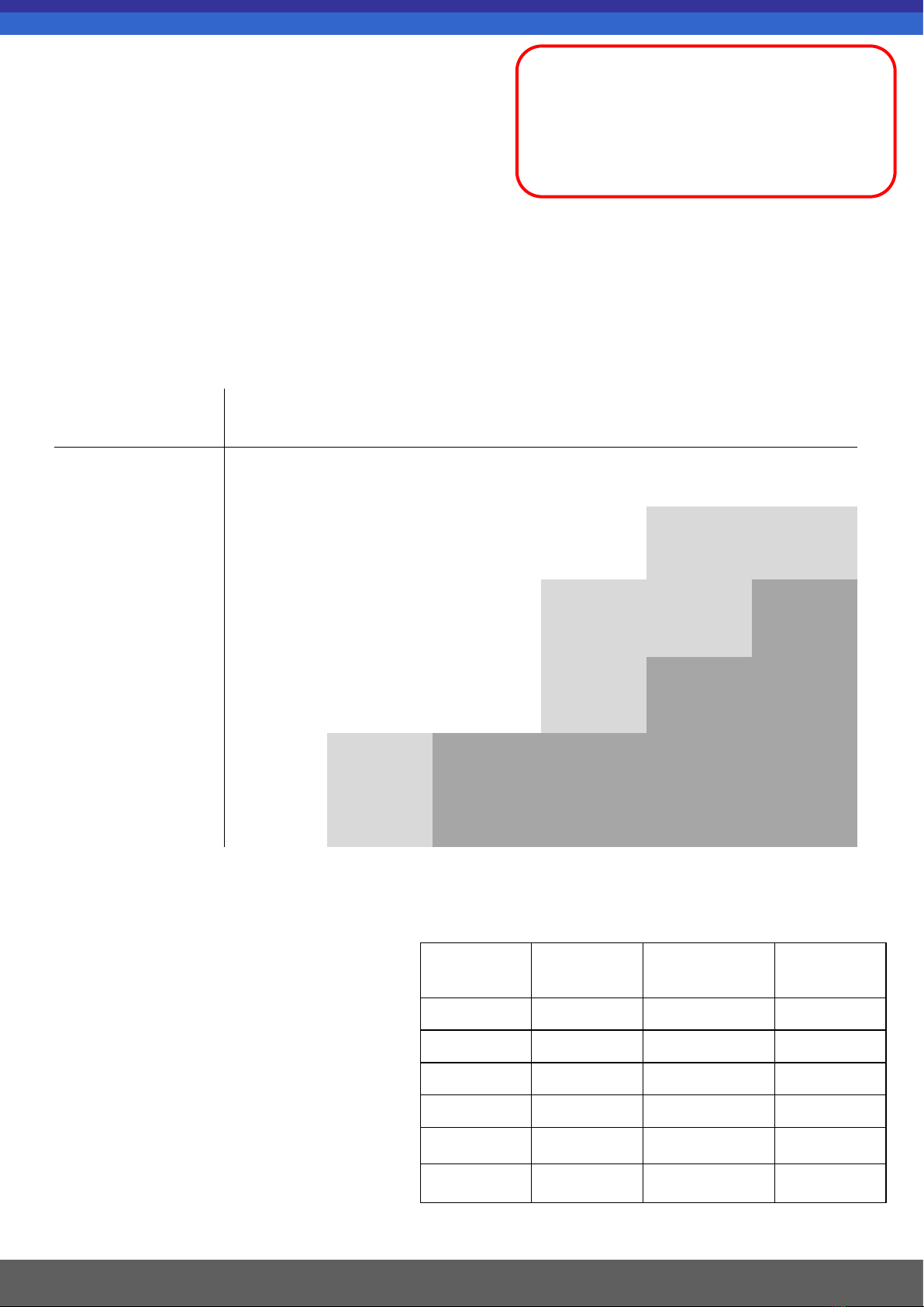
1M 2M 3M 4M 5M 6M
Slam 100x100 100x100 100x100 100x100 100x100 100x100
Single Hang 100x100 100x100 100x100 100x100 120x120 120x120
Double Hang
90 deg 100x100 100x100 100x100 120x120 120x120 150x150
Double Hang
Inline 100x100 100x100 100x100 120x120 150x150 150x150
Triple Hang 100x100 120x120 150x150 150x150 150x150 150x150
Quad Hang 100x100 120x120 150x150 150x150 150x150 150x150
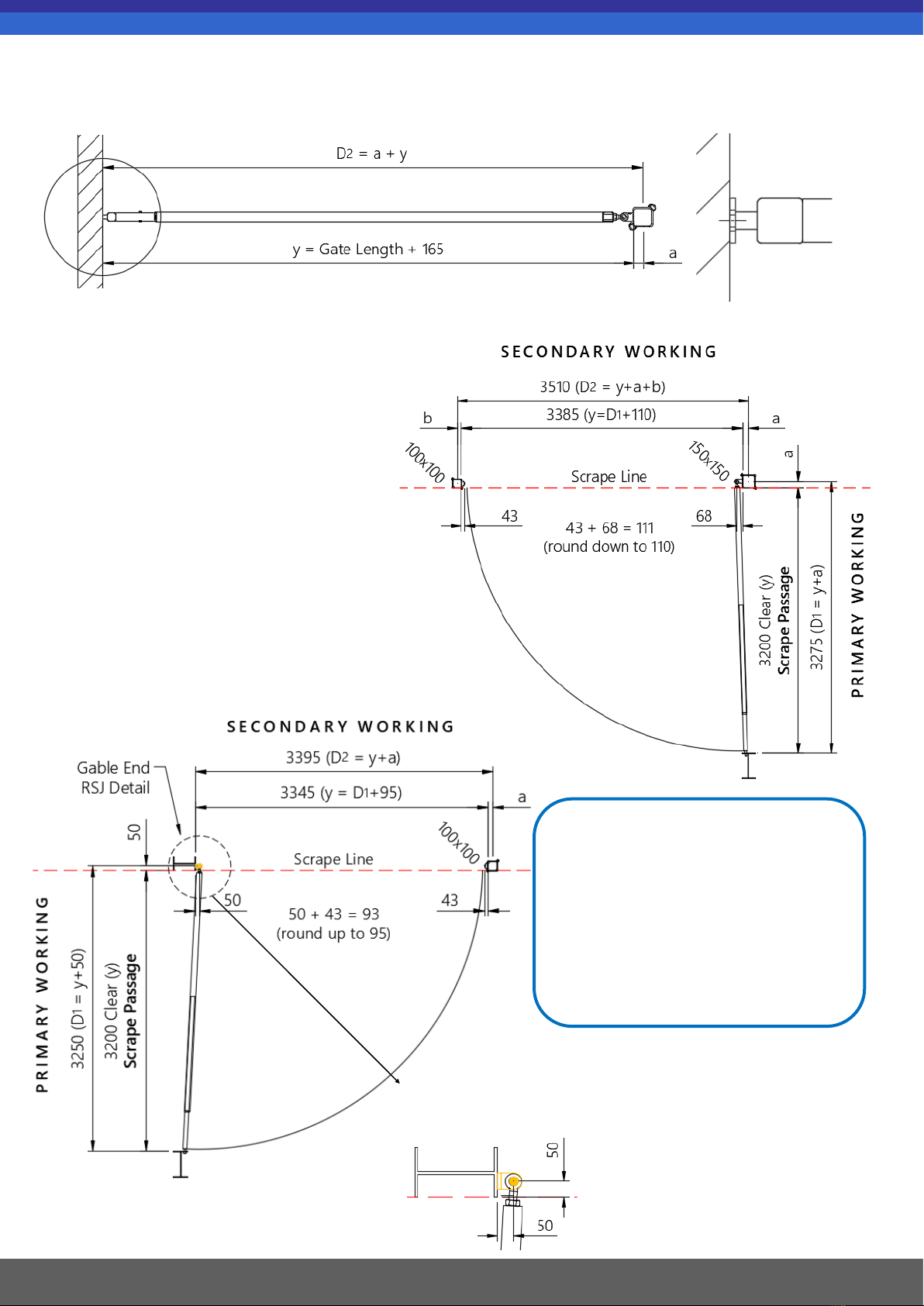
2.1. Post Selection
It is important to consider post selection at the
beginning of an AG-fit project install. The AG-fit posts
are available in a variety of different widths and lengths,
to ensure that you have selected the right post for your desired application you must consider
the following:-
• Gate or barrier length, see table below
• Post type i.e. hang or slam, see table below
• Height out of ground
Gate / Barrier Length (0.55M - 6M)
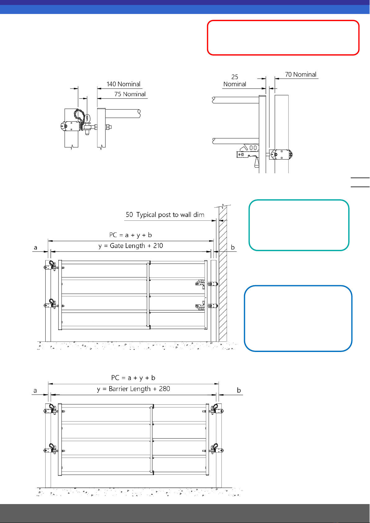
IMPORTANT:
Before inserting posts into ground be sure
to consider both; the depth of bedding
underneath (where 305mm rise is required
2440mm post must be used) and any steps
caused by discrepancy in the floor level.
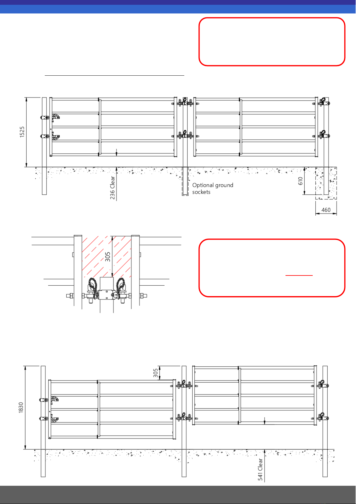
Heights Out Of Ground
Gates and barriers hanging at
1525mm as standard, use a 2135mm
post set 610mm deep into ground.
Gates and barriers with a 305mm rise
hanging at 1830mm, use a 2440mm
post set 610mm deep into ground.
Feed fence standing at 1370mm as
standard, use a 1830mm post set
460mm deep into ground.
Post Width
(mm) Post Length
(mm) Code Pack Size
100x100 1830 F030 2012 13 8
100x100 2135 F002 2009 01 8
120x120 2135 F002 2009 03 8
120x120 2440 1000197 2
150x150 2135 F002 2009 05 2
150x150 2440 1000193 2
2
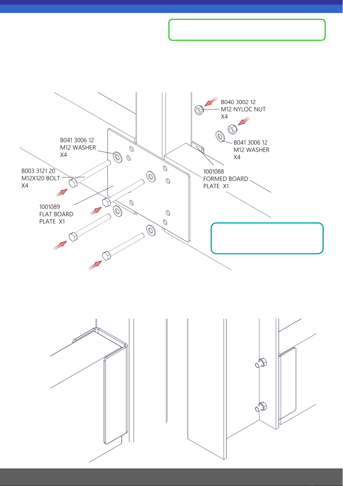
2. Post Installation
3
Guide For Available Posts;-
1001270 Volume 3.1 Issue Date: March 2021